94
fi
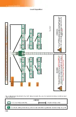
g. 6.1
7 - L
ਮਠਣ
C
ਠਯਠਢਨਲ਼ਨਤਲ
Load Capacities
WARNING
To ensure safety at all times on a mast climbing work platform system, bridges
must not be loaded beyond their maximum rated load capacities. Overloading
or incorrectly positioning loads on a mast climbing work platform system could
result in serious injury or death.
In a multiple unit linked setup equipped with weather protection, the
maximum length of cantilevers allowed on either side of the setup is
15' (4,6 m). Weather protection is not allowed in an unlinked confi guration.
Make sure that there is never more than one worker standing on the same plank
outrigger at the same time.
1-
The weight of planks and any additional accessory being used must be deducted
from the load capacities.
2- Each worker’s weight (personal tools and equipment included) must be deducted
from load capacities.
3-
To ensure stability, the
length of cantilevers
on either side of the unit must be
equal at
all times
. The loads must be applied on the platform as evenly distributed as possible.
4-
There must be a
maximum
number of workers for each installation, calculated as
follows: overall length of installation divided by 15' (4,6 m) and rounded
up,
PLUS
two workers for each motorized unit in the installation, with at least one of those two
workers being a qualifi ed operator of an F2 Series motorized unit and its accessories.
For example, on a setup with an overall length of 92' 9" (28,3 m), the calculation
would be: 92' 9" / 15 (or 28,3 m / 4,6 m) rounded up to
7
, PLUS
two
workers
for
each
motorized unit (in this case, two units) =
4
, resulting in a
maximum of 11 workers
for
the installation, including
two qualifi ed operators
. Refer to p. 7 of the
Performance
and Safety Rules
section for the defi nition of a qualifi ed operator.
5-
The weight of each person working in a given area reduces the load capacity of that area.
6- In a multiple unit linked setup equipped with weather protection, the maximum
length of cantilevers allowed on either side of the setup is 15' (4,6 m). Weather
protection is not allowed in an unlinked confi guration.
7- The load capacities charts stickers displayed on the motorized unit used in the
setup will take precedence over the information included in this owner’s manual.
8-
In the single unit and multiple unit installation charts shown in the following pages, the
5' (1,5 m) bridge is used to illustrate capacities. On setups using 10' (3 m) bridges,
the load deposited on the 10' (3 m) bridge must be distributed in the same way it is
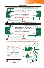
distributed over two 5' (1,5 m) bridges on the chart, as shown in fi g. 6.1, below.
Load capacity calculation guidelines
9-
To calculate the load capacity of a standard, authorized single or multiple unit confi guration
that is not shown in the charts included in this manual, take the length of the bridge to
be installed and refer to the capacities of the bridge in the chart that is longer and closest
to it. For example, for a 47' 6" (14,5 m) bearing bridge, the load capacities of a 50' (15,2 m)
bearing bridge would be used.
500 lb
227 kg
500 lb
227 kg
1000 lb
454 kg
2500 lb
1134 kg
500 lb
227 kg
500 lb
227 kg
1000 lb
454 kg
2500 lb
1134 kg
Total 4000 lb
2041 kg
Total 4000 lb
2041 kg
Combination of four 5' (1,5 m) bridges
Combination of two 10' (3 m) bridges
20' (6,1 m)
20' (6,1 m)


