background image


9.  Connecting and configuring DIO ports 


<Note>


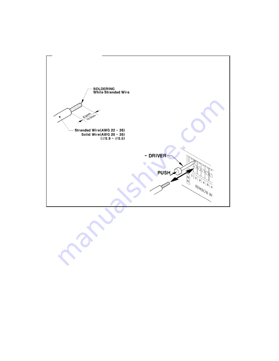
Wire Handling


Trimming Wire 

When connecting a wire to a terminal block, follow the instructions below. Note the different types of 

wire that can be used. 

Stranded Wire

: Peel off the wiring cover 

8~10mm and solder it. Wire gage should be 

AWG 22 ~ 26. 


Solid Wire:

 Peel off the wiring cover 8~10mm 

and solder it. Wire gage should be AWG 20 ~ 

26. 

Inserting & removing wire 


To insert the wire, use a screwdriver shown 

as in the diagram to the right. 


26 

Summary of Contents for HVR-16E

Page 1: ...HVR 16E Installation Guide v 3 1...

Page 2: ...accordance with the instruction manual may cause harmful interference to radio communications Operation of this equipment in a residential area is likely to cause harmful interference in which case th...

Page 3: ...the product including internal HDD In addition be sure the HVR is secured after installation 5 HVR is made of metal Therefore you can hurt human beings if yu throw it to them or hit on them When insta...

Page 4: ...word 16 6 Setting remote controller 17 6 1 Setting ID of HVR 16E 17 6 2 Selecting HVR 16E 18 6 3 Operable range of remote controller 18 6 4 Loading the batteries into remote controller 18 7 HVR 16E co...

Page 5: ...t 29 9 2 1 Specifications 29 9 2 2 Connecting relay out 29 9 2 3 Configuring relay out at OSD menu 30 9 3 Connecting serial port 31 9 3 1 Configuring serial ports for Pan Tilt Zoom 31 9 3 2 Diagrams o...

Page 6: ...er 44 12 2 Installing DVR Manager 44 12 3 Uninstalling DVR Manager 46 12 4 Configstation 47 12 5 Monitor 47 12 6 Playback 48 APPENDIX 49 1 HDD 50 1 1 Fundamental notions terms 50 1 2 Installing HDD 53...

Page 7: ...94 for external HDD ATM POS transaction information text recording and search with corresponding video 16 sensor inputs and 4 relay outputs Built in hardware motion detection with search function 64 d...

Page 8: ...es Unpack and check all the items as below 1 HVR 16E 1EA 2 AC Power Cord 1EA 3 CD ROM Including DVR Manager 1EA 4 Remote Controller 1EA 5 Guide 2EA 6 HDD Fixing KIT 1SET 7 19 RACK FIXING KIT 1SET 8 HD...

Page 9: ...9 HDD DATA CABLE 1EA 3 Description Function HVR 16E front 1 Power switch 2 Function buttons 3 LED 4 I O Port cover 5 USB connector 6 IEEE1394 connector 7 Remote controller receiver 9...

Page 10: ...BNC connector for monitor A output 12 BNC connector for monitor B output 13 Terminal block for sensor relay and serial input output 14 IEEE1394 connecter 15 Terminal block for RS232 422 485 16 Etherne...

Page 11: ...dance will be Hi z status Please refer to 9 6 Connecting Video In Output on page 39 3 Video type NTSC PAL should be changed after operating HVR 16E The order of camera recognition follows Ch1 camera t...

Page 12: ...4 2 Connecting monitor 1 Connect CCTV monitor to HVR 16E with BNC cable as shown below 4 3 Connecting audio 1 Connect audio signal to HVR 16E with using RCA cable 12...

Page 13: ...nnect Power Cable Note 1 When supplying power HVR 16E starts booting automatically 2 In order to cut off power press the 1 power switch on HVR 16E front during 5 seconds 3 For supplying power again pu...

Page 14: ...4 5 Connecting VGA 1 Connect VGA Monitor to HVR 16E using VGA cable shown as below figure 14...

Page 15: ...ting page will be shown to the right of the sub menu Use the arrow buttons to move within the sub menu list To move to the setting page press the ENTER button To exit the setting page press the EXIT b...

Page 16: ...s 3 and 2 buttons 2 Using arrow button Select a value using the or buttons The intersection of the horizontal and vertical bar is selected value For example select C and press the button to confirm th...

Page 17: ...or button 3 Select Miscellaneous from the sub menu list using the button and press the ENETR button 4 Select Remote Control ID and press the ENETR button 5 Select a value using the buttons and press...

Page 18: ...ring 2 seconds Note Because remote controller ID is sixteen HVR will correspond until pressing ID button sixteen times 6 3 Operable range of remote controller 6 4 Loading the batteries into remote con...

Page 19: ...7 HVR 16E configuration 7 1 Basic configuration 7 2 Advanced configuration 19...

Page 20: ...7 3 External storage Backup configuration 7 4 Internet Intranet configuration 20...

Page 21: ...are displayed in multi split screen according to the connected channels The following example is when 4 channels are connected Note If user password is set a prompt for entering the password will appe...

Page 22: ...hen finished 8 2 2 Daylight saving 1 Daylight Saving Time is only activated for time zones that use Daylight Savings If activated press ENTER to enter a new value 2 Select On Off using the button and...

Page 23: ...using the or the buttons and press ENTER 2 Select HH MM using the buttons and select the value using the buttons 3 Press the EXIT button when finished 8 2 7 Apply Date Time Most setting values are ap...

Page 24: ...menu by pressing ENTER or the button 3 Select Recording using the buttons and press the ENTER button 8 3 1 Configuration status Displays the recording configuration status When setting up through the...

Page 25: ...d ips When Recording Speed Quality is set as Custom values can be set manually 1 Select Speed using buttons and press the ENTER button 2 Select a value using the button Press the EXIT button when fini...

Page 26: ...s below Note the different types of wire that can be used Stranded Wire Peel off the wiring cover 8 10mm and solder it Wire gage should be AWG 22 26 Solid Wire Peel off the wiring cover 8 10mm and sol...

Page 27: ...nsor Dry contact Spec Connecting Connecting the trimmed wire to terminal block Available input pulse range Min 500ms Performance Output current Typical DC 12mA 9 1 2 Connecting sensor input Connect S1...

Page 28: ...pen N O and Normal Close N C 1 Select a Global and set a type as Off N O or N C 2 Press Apply to save a configuration 9 1 3 2 Configuration Use when selecting each 16 sensor individually 1 Select a Co...

Page 29: ...Ch Rrelay differential outputs Output type Dry Contact Spec Connecting type Connect the trimmed wire to terminal block 24V DC 1 25A 30W DC 125V DC 0 24A 30W 125V AC 0 5A 62 5VA Rating AC 250V AC 0 25A...

Page 30: ...nsor or MD and its condition can be set differently according to schedule When using the Relay button Number button on the front panel or DVR Manager S W relay can be operated from remote site Note Pl...

Page 31: ...ntrolled using the Transparent Protocol For a list of supported protocols refer to the list on the OSD Configuration menu The following figure shows how to connect PTZ camera to RS485 COM2 When using...

Page 32: ...9 3 2 2 Diagram of COM2 RS422 485 9 3 2 3 Diagram of COM3 RS232 9 3 2 4 Diagram of COM4 RS422 485 32...

Page 33: ...9 3 3 View of COM3 COM4 serial ports Configurin nu Configure PTZ COM ports and available modes at System Serial Setup 9 3 4 g COM port at OSD me 33...

Page 34: ...After completing serial setup configure base address or port for each channel at Camera menu tab When connecting PTZ devices to several cameras be sure base address matches address for the camera 34...

Page 35: ...t to COM1 RS232 9pin D Sub of HVR 16E and configure the Serial Setup sub menu under the System tab and Text sub menu under the Alarm Source tab shown as above figure 9 4 2 Configuring serial setup COM...

Page 36: ...t the Alarm Source menu among OSD menus 2 Select the Text and set each value Note Before installing any external device consult with the local HUNT ELECTRONIC distributor Some external devices may not...

Page 37: ...Current Max 200mA per DC 5V Port Note The disk should be formatted with FAT32 type as in the following picture To copy images p to 1 minute Select drive Copy press Start If properly connected the dis...

Page 38: ...when vi nected o impedance is changed as Hi z So in this case v al v nitor should be set as 75 HVR s video in output is composed of Loop Through HVR recognizes the connection status and video impedanc...

Page 39: ...ONIC distributor 10 2 Connecting IEEE1394 device When using FireWire supported external HDD hard drive bays can be connected to 1 port in the front panel or 1 port in the rear panel The DS1600 series...

Page 40: ...s Model No Size Series Model No Size used HUNT ELECTRONIC Manufacturer MAXTOR 6Y060L0 60GB 4R060L0 60GB 6Y080L P 0 80GB 4R080L0 80GB 6Y120L P 0 120GB 4R120L0 120GB DiamondMax 6Y160L P 0 160GB 4R160L0...

Page 41: ...s F using button and press EXIT button Select Action using button and press EXIT button Select Add using button and press EXIT button Select Apply using button and press EXIT button The HDD status is...

Page 42: ...local access for controlling monitoring features 1 Turn off HVR 16E s power switch 2 Connect HVR 16E to hub with Ethernet cable 3 Turn on HVR 16E s power switch Note 1 Supply power to HVR 16E after co...

Page 43: ...nd press ENTER Press EXIT button after entering Net Mask in the dialogue box Select Gateway using the buttons and press ENTER Press EXIT button after entering Gateway in the dialogue box 0 Select DNS...

Page 44: ...128 MB or above OS Windows 2000 SP4 XP SP2 or above Windows 2000 SP4 XP SP2 or above Resolution 1024 X 768 pixels or above 1024 X 768 pixels or above Network 100 Base TX Fast Ethernet 100 Base TX Fas...

Page 45: ...for DVR Manager press the Next button 6 Browse and choose a directory if the default directory is not preferred Click the Install button after selecting a directory to install 7 Click the Close button...

Page 46: ...12 3 Uninstalling DVR Manager 1 Click Windows Start Button 2 Digital Image World DVR Manager Uninstall 3 DVR Manager program will be automatically deleted 46...

Page 47: ...12 4 Configstation Clic he icon on deskt p to run DVR k t o Manager Configstation Tools 12 5 Monitor Click the icon on desktop to run DVR Manager Monitor program 47...

Page 48: ...12 6 Playback Click the icon on desktop to run DVR Manager Playback program 48...

Page 49: ...APPENDIX APPENDIX 49...

Page 50: ...ds are divided into primary disk connected firstly and auxillary disk Note ATA or EIDE supports two channel interfaces Primary Secondary Each channel can be connected to two devices Master Slave HDD C...

Page 51: ...as normal recording schedule Alarm Partition To store the data as alarm recording condition MD or Sensor Backup 1 Backup is possible only through IEEE1394 port and HDD for backup should be formatted a...

Page 52: ...red by the order of recognition HDD Managing Command 3 Add Add a HDD for recording In case of adding a disk Alarm Partition menu is activated as an available status Alarm Partition means that one HDD...

Page 53: ...60GB 4R060L0 60GB 6Y080L P 0 80GB 4R080L0 80GB 6Y120L P 0 120GB 4R120L0 120GB 6Y160L P 0 160GB 4R160L0 160GB 6Y200P0 200GB DiamondMax Pl pm 6Y250P0 250GB ax DiamondM 16 us 9 7200r 5400rpm Note L seri...

Page 54: ...3 Remove the 6 screws as illustrated below and pull up the cover from the rear part to open Remove 4 HDD Bracket screws and take out HDD BRACKET 4 54...

Page 55: ...th cable with HDD Note When assembling a HDD the back side of HDD should be with HDD BRACKET shown as above figure 6 Assemble cables according to the following numbers Please be careful to the HDD DAT...

Page 56: ...ssemble the top cover Note Caution for HDD Management 1 Replacing SLAVE HDD of internal 2 HDDs causes permanent data loss in the SLAVE HDD 2 MASTER HDD has all the index of stored data including SLAVE...

Page 57: ...t it 3 Select Action as Add configure a size of alarm partition and press Apply button Then F is changed to R Note 1 Alarm partition can be set from 10 to 90 within the size of primary disk 0 alarm pa...

Page 58: ...primary disk IntA or IntB Select Action 4 as Add configure a size of alarm partition and press Apply button Then F is to R changed 5 Select a HDD for installing as auxiliary disk 6 Select Action as Ad...

Page 59: ...1port of IEEE1394 HVR 16E supports upto 4TB storage Note 1 Some IEEE1394 ports may not be recognized by the HVR 16E Before purchasing consult the local HUNT ELECTRONIC distributor 2 External storage s...

Page 60: ...2 Select a second HDD of F Ext Press the Apply button after selecting action as Add Then F is changed to R Note If connecting the device that is used in HVR 16E type will be indicated as V 3 Select a...

Page 61: ...r to the manual of related device 1 When external HDD RAID is connected to IEEE1394 port Disk Manager runs automatically If not run it manually in Menu Utility Disk Manager n as Add Then F is changed...

Page 62: ...size of alarm partition Press the Apply button after selecting action as Add hen F is changed to R It is wh If con the device that is used in HVR 16E type will be indicated as V en Ext is added as pr...

Page 63: ...e a size of alarm partition Press the Apply button o not run it manually in Menu Utility Disk Manager 2 Sele after selecting action as Add Then F is changed to R Note It is when Ext is added as primar...

Page 64: ...k range or image searching per event is impossible 2 When recording is stopped and Disk Manager shows HDD type as X When disk is broken In case of not reading or writing a disk comes from physical err...

Page 65: ...kup range and press the Start button after selecting backup HDD Note 5 1 Backup HDD should be formatted as FAT32 type Backup data can be replayed with specific S W in PC such as DVR Manager or MiniPla...

Page 66: ...th recorded image it is possible only when HDD is installed and used in DS1600 includin A HDD and th Note The preserved HDD s data is possible to replaying only when it is connected to HVR 16E 1 5 Cau...

Page 67: ...r setting should be changed inside the case Jumper Setting Video Type Remark 1 2 NTSC Video 2 3 PAL Video Note In order to change video type contact the closest local HUNT ELECTRONIC diatributor HUNT...

Page 68: ...porting VGA t HVR 1600D M1 chan onnector of 15 pin D Su w mode hout removin 3 2 Configuring serial port for Pan Tilt Zoom In case of supporting DS1600 Series through COM1 port it is possible to contro...

Page 69: ...data received from POS ATM through the In VGA COM1 port After connecting to VGA COM1 15pin D Sub of HVR 16E configure the Serial Setup under the system menu and Text sub menu under the Alarm Source t...

Page 70: ...Acrobat Reader Version 5 1 Note Preparation To read manual of CD ROM disc Adobe Acrobat 5 0 should be installed in client s PC If Adobe Acrobat Reader is not installed within client s PC use the Acrob...

Page 71: ...hannel if 8ch used Max 7 5ips NTSC per channel if 16ch used layback performance Max 60ips NTSC 50ips PAL layback speed 1ch 4ch 9ch 16ch 1x 2x 4x 8x 16x Forward Reverse playback layback search Instant...

Page 72: ...ade Firmw Simultaneous users Monito Playback Max 5 u Security Password User or Administrator Authentic Monitoring Max 960fps fps field per second Monitoring screen 1ch 4ch 9ch 13ch 16ch Auto Sequentia...

Page 73: ...s Conditions Normal Event g POS ATM transaction information archived along with corresponding video data Electricity applied adaptor C D 62 5VA Digital ou Daily Day Night Four segment tim Weekly Weekd...

Page 74: ...Power consumption Dimension W D H Max 85W Internal 2 HDD Typical 50W Internal 2 HDD Mechanical 430 0 x 362 0 x 44 0 Weight 5 5 kg with one HDD 74...

Page 75: ...Hunt Electronic USA 978 W 10th Street Azusa CA 91702 Tel 626 812 8868 Fax 626 812 8828 info huntcctv com www huntcctv com...

Reviews: