Interfaces and software update
OPERATION MANUAL
Chapter 6
Unistat® T300 Series
Liability for errors and misprints excluded.
V1.2.0en/12.05.15//14.06
74
▪
“Process temperature relative”:
Set the upper and lower limit of a temperature range around the
setpoint by using the POKO “min. value” and the POKO “max. value”.
The potential-free contact indicates the condition, that the setpoint differs from the actual value
by a smaller difference than was defined by the temperature range. Exceeding the set range only
results in the potential-free contact to switch (away from the OK state), but does not result in fur-
ther reactions of the temperature control unit. The contact returns to the OK status if the actual
value is within that range.
▪
“Unipump with Echo”:
This function is used to check whether the Unipump controlled by the
POKO runs synchronous with the Unistat pump. For this purpose, the operating mode of the
Unipump is applied via a make contact to the “LEVEL” socket. A fault is generated if asynchro-
nous. This mode is useful if a Unipump is to be monitored - either to guarantee the desired circu-
lation or to prevent an unintended heating of the thermal fluid.
▪
“Programmer”:
This activates the individual segments associated during program creation with
the POKO switching states.
▪
“Internal temperature absolute”:
This enables you to set a temperature range relative to the
internal sensor (absolute temperature). The POCO is active outside of this range; the POCO is in-
active inside of this range.
▪
“Process temperature absolute”:
This enables you to set a temperature range relative to the
process temperature (absolute temperature). The POCO is active outside of this range; the POCO
is inactive inside of this range.
With the floating contact, use only sheathed lines! The interface is specified as a digital output.
The connection is designed as a potential-free changeover contact.
Closing contact between pin 1 and pin 2.
Opening contact between pin 2 and pin 3.
Contact load: 1 A at 24 V DC.
6.3.3
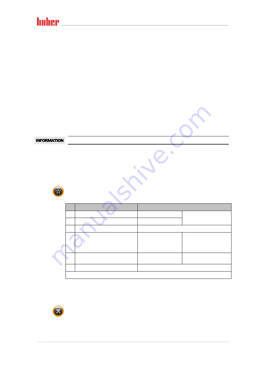
Jack AIF Reg-E-Prog
The analog interface has a programmable input channel and 3 output channels.
The analog interface of Com.G@te® is programmed in the category “Interfaces”.
Pin
Description
Signal
1
Current output, T external
0
a)
/4 - 20 mA or 0 - 10 V
If using 0 - 10 V, integrate a
500 Ω resistor.
2
Current output, setpoint
0
a)
/4 - 20 mA or 0 - 10 V
3
GND for analog outputs
GND
4
Analog input (programmable)
0
a)
/4 - 20 mA or 0 - 10 V
Power input: 200 Ω working
resistance
Voltage input: 100 kΩ input
resistance
5
Current output, freely programmable
0
a)
/4 - 20 mA or 0 - 10 V
If using 0 - 10 V, integrate a
500 Ω resistor.
6
GND for analog input
GND
a)
Consult with our Customer Support.
6.3.4
Jack ECS (External Control Signal) standby
Enable signal
ECS
(external control signal) for starting/stopping the temperature control process.
Activation via a floating contact. Contacts 1 and 3 are internally bypassed.
ECS
is energized when E1
and E2 are connected by an external floating contact.
The functionality of the
ECS
is determined via the “Interfaces” category.
Pin assignment


