background image

6.3 Alarm Reference

NO TICE

If the Clear icon is displayed on the Details screen, the alarm can be manually

cleared by tapping the Clear button after the fault is rectified. The alarm

clearance type (automatic or manual) varies with smart cooling products. Alarms

can be cleared are a025, a058, a061, a062, a064, a076, a079, a095.

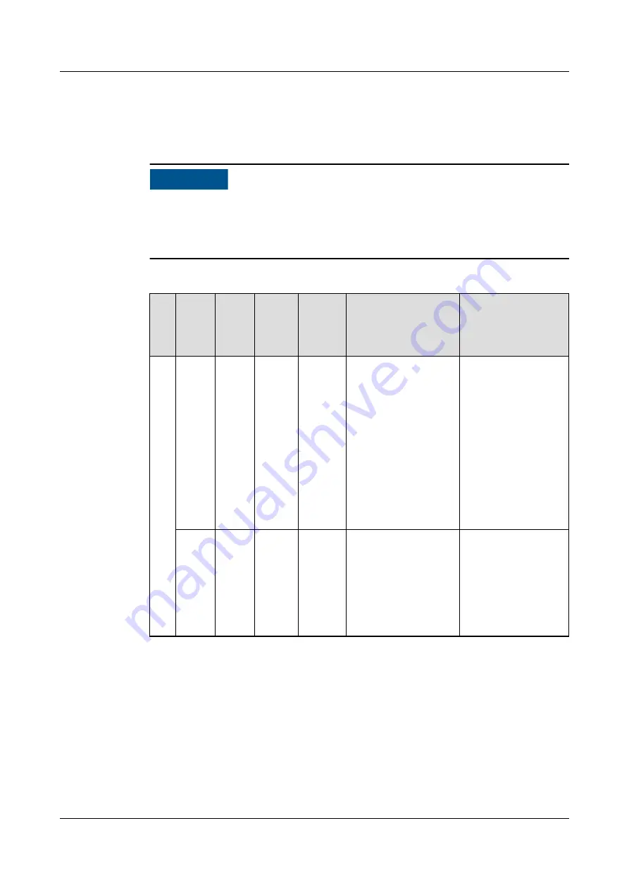
Table 6-6 Alarm description

Al

ar

m

ID

Alar

m

Alar

m

Seve

rity

Defau

lt

Value

Impac

t

Possible Cause

Solution

a0

01

Retur

n-air

1

temp

invali

d
Retur

n-air

2

temp

invali

d

Majo

r

N/A

The

alarm

is

genera

ted.

1. The cables to the

temp sensor are

loose or

damaged.

2. The temp sensor

is faulty.

1. Check the

cables to the

temp sensor.

2. Maintain or

replace the

temp sensor.

Retur

n-air

3

temp

invali

d

Majo

r

N/A

The

alarm

is

genera

ted.

1. Dirt or water

exists around the

T/H sensor,

which leads to a

detection fault.

2. The T/H sensor

is faulty.

1. Remove dirt or

water from the

T/H sensor.

2. Maintain or

replace the T/H

sensor.

NetCol5000-A(025, 035) In-row Air Cooled Smart

Cooling Product

User Manual (600 mm Width)

6 System Operation and Maintenance

Issue 17 (2020-10-22)

Copyright © Huawei Technologies Co., Ltd.

160

Summary of Contents for NetCol5000-A-035

Page 1: ...NetCol5000 A 025 035 In row Air Cooled Smart Cooling Product User Manual 600 mm Width Issue 17 Date 2020 10 22 HUAWEI TECHNOLOGIES CO LTD ...

Page 2: ...cribed in this document may not be within the purchase scope or the usage scope Unless otherwise specified in the contract all statements information and recommendations in this document are provided AS IS without warranties guarantees or representations of any kind either express or implied The information in this document is subject to change without notice Every effort has been made in the prep...

Page 3: ...and maintenance O M The figures provided in this document are for reference only Intended Audience This document is intended for Sales personnel Technical support personnel System engineers Hardware installation personnel Commissioning engineers Data configuration engineers Maintenance personnel Symbol Conventions The symbols that may be found in this document are defined as follows Symbol Descrip...

Page 4: ...ed to address information not related to personal injury equipment damage and environment deterioration Change History Updated the method of restoring the controller to factory settings Issue 17 2020 10 22 Added section Replacing the High Pressure Switch Issue 16 2020 07 03 Deleting the SNMP Protocol Issue 15 2020 05 18 Updated the method of restoring the controllsafety information Issue 14 2020 0...

Page 5: ...itoring installing enclosure frames and upper frames and connecting signal cables Issue 06 2015 07 02 Modified the requirement of leak checking vacuuming and partially charging refrigerant Issue 05 2014 11 27 Added reducing valve requirement when leak checking Issue 04 2014 10 30 Modified the following expressions Added table 5 9 A cold aisle temperature and humidity sensor was configured in secti...

Page 6: ...4 05 30 This issue is the first official release NetCol5000 A 025 035 In row Air Cooled Smart Cooling Product User Manual 600 mm Width About This Document Issue 17 2020 10 22 Copyright Huawei Technologies Co Ltd v ...

Page 7: ...4 Technical Specifications 21 3 Installation Guide 24 3 1 Installation Preparation 24 3 1 1 Tools 24 3 1 2 Material Preparations 28 3 1 2 1 Optional Refrigerant R410A 28 3 1 2 2 Refrigerant Oil 30 3 1 2 3 Pipe Components 30 3 1 2 4 Humidifier Water Inlet Pipe Pump Drainpipe and Automatic Drainpipe 31 3 1 2 5 Pipe Support 33 3 1 2 6 Cables 33 3 1 3 Deployment Principles 35 3 2 Unpacking 36 3 3 Chec...

Page 8: ...onnecting the Outdoor Unit On Off Signal Cable 72 3 11 4 2 Connecting Water Sensor 73 3 11 5 Teamwork Networking and Monitoring 74 3 11 6 Installing a Humidity and Temperature Sensor Outside the Cabinet 78 3 11 7 Connecting Monitoring Cable from FE Port 82 3 12 Connections Verification 82 4 ACC Introduction 85 4 1 Appearance 85 4 2 Controller Ports 86 4 3 Home Screen 86 4 4 Menu Hierarchy 88 4 5 P...

Page 9: ...ode 126 4 7 6 How to Fast Shut Down an Smart Cooling Product 127 4 7 7 How to Manually Clear Alarms 127 4 7 8 How to Enable a Humidity and Temperature Sensor 128 4 7 9 How to Check Teamwork Control Information 128 4 7 10 Which Parameters Are Restored to Default Values After Default Settings Are Operated 129 4 7 11 How to Change the SSH Access Password 129 4 7 12 Rectifying Faults of the E label Id...

Page 10: ...ters 204 6 5 2 Replacing a Indoor Fan 205 6 5 3 Replacing a Compressor 207 6 5 4 Replacing the High Pressure Switch 210 6 5 5 Replacing Compressor Drive 212 6 5 5 1 Replacing a Huawei Compressor Drive 212 6 5 5 2 Replacing a Danfoss Compressor Drive 216 6 5 6 Replacing Condensate Pump 218 6 5 7 Replacing Humidifier Cylinder 220 6 5 8 Replacing Electric Heater 222 A Electrical Ports of an Indoor Un...

Page 11: ...local laws and regulations when installing operating or maintaining the equipment The safety instructions in this document are only supplements to local laws and regulations Huawei will not be liable for any consequences of the following circumstances Operation beyond the conditions specified in this document Installation or use in environments which are not specified in relevant international or ...

Page 12: ...operation and maintenance Before handling a conductor surface or terminal measure the contact point voltage and ensure that there is no risk of electric shock After installing the equipment remove idle packing materials such as cartons foam plastics and cable ties from the equipment area In the case of a fire immediately leave the building or the equipment area and turn on the fire alarm bell or m...

Page 13: ...ng equipment transportation or installation in a timely manner Equipment with scratches cannot be exposed to an outdoor environment for a long period of time Before operations ensure that the equipment is firmly secured to the floor or other solid objects such as a wall or an installation rack Do not use water to clean electrical components inside or outside of a cabinet Do not change the structur...

Page 14: ...als personnel who are trained or experienced in equipment operations and are clear of the sources and degree of various potential hazards in equipment installation operation maintenance Trained personnel personnel who are technically trained have required experience are aware of possible hazards on themselves in certain operations and are able to take protective measures to minimize the hazards on...

Page 15: ...es must be performed by qualified personnel Cabling When routing cables ensure that a distance of at least 30 mm exists between the cables and heat generating components or areas This prevents damage to the insulation layer of the cables Do not route cables behind the air intake and exhaust vents of the equipment Ensure that cables meet the VW 1 or ZB flame spread rating requirements or higher Bin...

Page 16: ...g materials before storing or transporting them Figure 1 1 Wearing an ESD wrist strap Neutral Ground Voltage It is recommended that the three phase loads be equalized and the neutral ground voltage be kept at less than 2 V to meet power distribution requirements 1 4 Installation Environment Requirements To prevent fire due to high temperature ensure that the ventilation vents or heat dissipation s...

Page 17: ...r personal protective equipment such as the safety helmet and safety belt or waist rope and fasten it to a solid structure Do not mount it on an insecure moveable object or metal object with sharp edges Make sure that the hooks will not slide off Set a restricted area and eye catching signs for working at heights to warn away irrelevant personnel Carry the operation machinery and tools properly to...

Page 18: ...glass ladders when you need to perform live working at heights When a step ladder is used ensure that the pull ropes are secured and the ladder is held firm Before using a ladder check that it is intact and confirm its load bearing capacity Do not overload it Ensure that the ladder is securely positioned The recommended angle for a ladder against the floor is 75 degrees as shown in the following f...

Page 19: ...side Metal shavings from drilling may short circuit boards inside the equipment Obtain the consent from the customer and subcontractor before drilling Wear goggles and protective gloves when drilling holes When drilling holes protect the equipment from shavings After drilling clean up any shavings that have accumulated inside or outside the equipment Moving Heavy Objects DANGER When removing a hea...

Page 20: ...afety Welding At least two persons are required on a welding site A welder must have a work permit A welding site must be free from inflammables Ensure that a fire extinguisher wet wiper and water container are available A burning welding torch must not be placed on a component or on the floor and must not be placed in a metal container with acetylene and oxygen Otherwise the gas may leak and caus...

Page 21: ...r wastes that have a shell in European Union EU areas To avoid environment pollution and harm to human health wastes must be classified and recycled This also promotes resource reuse When recycling a device fill in the device information in the recycling collection system or contact your dealer for help The dealer can help you recycle devices in a safe and environment friendly way 1 7 Others Exerc...

Page 22: ... 1 shows the naming rule for the NetCol5000 A series products Figure 2 1 Naming rule NetCol5000 A 025 035 In row Air Cooled Smart Cooling Product User Manual 600 mm Width 2 Product Description Issue 17 2020 10 22 Copyright Huawei Technologies Co Ltd 12 ...

Page 23: ...interconnected and circulate using the refrigerant pipes in a sealing manner The NetCol5000 A consists of an indoor unit and an outdoor unit the NetCol500 A072 is used as an example as shown in Figure 2 2 Figure 2 2 Product components 1 NetCol5000 A 2 NetCol500 A072 2 2 1 Indoor Unit Appearance Figure 2 3 shows the NetCol5000 A indoor unit NetCol5000 A 025 035 In row Air Cooled Smart Cooling Produ...

Page 24: ...ater optional electrode humidifier optional and condensate pump optional Compressor The indoor unit uses the advanced DC frequency converting scroll compressor to adapt to broad working conditions The compressor features good environment adaptability stepless frequency adjustment precise temperature control energy conservation high reliability low noise long service timlife and easy installation T...

Page 25: ...ating capacity and even heating Electrode humidifier The electrode humidifier provides stepless adjustment of humidification capacity and precise control of humidity in the equipment room Condensate pump The condensate pump is made of thermostable materials which ensure that the condensate water and hot water from the humidifier are exhausted efficiently The pump lift is 3 5 m Two floats are used ...

Page 26: ...The controller controls the smart cooling product precisely and responds quickly The multi level password protection prevents misoperations The controller provides multiple protection functions such as chilled water valve exception feedback abnormal power off self recovery and water leakage detection ensuring system reliability The LCD on the controller displays the operating status and duration o...

Page 27: ...e smart cooling products as the master unit and connect the master unit to the monitoring network Figure 2 5 shows a diagram of the monitoring network Figure 2 5 Networking diagram 2 3 Working Conditions Environmental Specifications NOTE Do not install the smart cooling product near a noise sensitive place such as an office or a conference room Table 2 2 Operation conditions Item Specifications Op...

Page 28: ... to 1000 m If the altitude is greater than 1000 m the cooling performance deteriorates Table 2 4 describes the derating coefficients Table 2 3 Storage conditions Item Specifications Storage temperature 40 C to 70 C Storage humidity 5 RH to 95 RH non condensing Table 2 4 Derating coefficients Altitude 0 m 1000 m 1500 m 2000 m 2500 m 3000 m 3500 m 4000 m Density coefficient 1 0 887 0 835 0 785 0 737...

Page 29: ...ctor as shown in Figure 2 6 Figure 2 6 Screw thread connector NOTE BSPP 1 2 inch Large diameter 20 955 mm medium diameter 19 793 mm small diameter 18 631 mm medium diameter tolerance 0 0 142 mm small diameter tolerance 0 0 541 mm Installation requirements Table 2 6 describes the installation requirements of NetCol5000 A NOTICE When the total load of servers relative to a single smart cooling produ...

Page 30: ...0 C Transient flow is greater than or equal to 0 6 L min The quality of supplied water must meet the requirements listed in Table 2 7 Drain Water The upper drainage height of the condensate pump should be 3 5 meters at most Self drainpipe inner diameter 19 mm self drainage leveling tube length 2 m The hose can be used in a environment whose temperature is higher than 85 C The requirement is only f...

Page 31: ...able 2 7 describes NetCol5000 A water quality requirements Table 2 7 Water quality requirements Name Specifications Unit Hydrogenion 7 8 5 pH Conductivity rate at 20 C σ20 a 300 1250 μS cm a When σ20 is less than 300 μS cm the first vapor exhausting duration of the humidifier is long when σ20 greater than 1250 μS cm the humidifier service life is affected 2 4 Technical Specifications Table 2 8 Gen...

Page 32: ...tion functions or partial heating and humidification functions are recommended The condensate pump is mandatory for scenarios where pipes are routed from the top or if it is required by the customer Table 2 9 Optional Parameters of NetCol5000 A035 Item NetCol5000 A035H512D2 E120E1 NetCol5000 A035H512D2 E120E0 NetCol5000 A035H512D2 0020E1 NetCol5000 A035H512D2 0020E0 Max Current 32 A 32 A 26 A 26 A...

Page 33: ...020E0 Max Current 29 A 29 A 23 A 23 A Condensate pump Yes No Yes No Reheat Yes Yes No No Humidify Yes Yes No No Reheating capacity 6 0 kW 6 0 kW N A N A Humidifying capacity 3 0 kg h 3 0 kg h N A N A NetCol5000 A 025 035 In row Air Cooled Smart Cooling Product User Manual 600 mm Width 2 Product Description Issue 17 2020 10 22 Copyright Huawei Technologies Co Ltd 23 ...

Page 34: ...Col5000 A Add or delete tools as required Table 3 1 General tools Appearance specifications and name Adjustable wrench Phillips screwdriver M4 M6 and M8 Flat head screwdriver M3 and M4 Socket wrench 18 mm Torque wrench 28 mm Solid wrench 18 mm and 13 mm Box end wrench Diagonal pliers NetCol5000 A 025 035 In row Air Cooled Smart Cooling Product User Manual 600 mm Width 3 Installation Guide Issue 17...

Page 35: ...t or seal tape for thermal insulation foam must be able to withstand temperatures higher than 85 C Table 3 2 Translating tools Appearance specifications and name Manual pallet truck Electrical pallet truck Lifting rope bearing at least 400 kg Lever bearing at least 400 kg NetCol5000 A 025 035 In row Air Cooled Smart Cooling Product User Manual 600 mm Width 3 Installation Guide Issue 17 2020 10 22 ...

Page 36: ...ipe thread sealant with polytetrafluorethylene PTFE for short as the filler The glycol solution resistance and adapt to the thread size with pipeline Maximum seal gap is less than 0 5 mm The maximum pressure is greater than 3 MPa Conforms to JB T7311 2008 engineering mechanical the anaerobic adhesive application technology specification profession standard Table 3 4 Connecting cable tools Appearan...

Page 37: ... 4 0 MPa and the tolerance range of the leather hose must be greater than or equal to 4 5 MPa The size of needle valve in the unit is 1 4 inch Purchase a conversion adapter if you have a different size of valve on leather hoses b The rate flow between 2 L s 7 2 m3 h and 4 L s 14 4 m3 h is recommended Absolute vacuum 60 Pa c Dry nitrogen d A reducing valve needs to install to the outlet of the nitr...

Page 38: ...ponents and supports Humidifier water supply drainage components Cables and electric device Mandatory N A Hose clamp L1 L2 L3 and PE terminals 18 PCS voltage jumper 6 PCS water sensor 1 PCS teamwork networking cable 1 PCS humidity and temperature sensor 1 PCS Optional Pipe components including R410A copper pipes thermal insulation foam oil traps and inverted traps N A Indoor unit power cable outdo...

Page 39: ...ion from the measured internal pressure If the deviation is more than 0 2 MPa the refrigerant is not qualified and should be replaced Figure 3 1 Checking refrigerant Table 3 7 Mapping between temperatures and R410A saturation pressure Temperature C Saturation Pressure Surface Pressure MPa Temperatur e C Saturatio n Pressure Surface Pressure MPa Temperatu re C Saturati on Pressur e Surface Pressur ...

Page 40: ... not ignore the refrigerant oil 3 1 2 3 Pipe Components Pipe components are optional and include Liquid pipe copper pipe for R410A external diameter 5 8 inch thickness 1 0 mm pressure tolerance range 4 5 MPa Gas pipe copper pipe for R410A external diameter 7 8 inch thickness 1 2 mm pressure tolerance range 4 5 MPa Thermal insulation foam thickness 13 mm Oil traps and inverted traps To ensure the N...

Page 41: ...ring inner diameters at both ends of the copper pipe are 16 3 mm Note After the traps are made verify that the surface is smooth and even 3 1 2 4 Humidifier Water Inlet Pipe Pump Drainpipe and Automatic Drainpipe NOTICE Drainpipes must be able to withstand temperatures higher than 85 C Otherwise the pipes may be deformed This notice is for the equipment configured with a humidifier Table 3 9 and F...

Page 42: ...e with external threads 2 Rigid pipe made of PP R C PVC or other materials 3 Pagoda connector as shown in Figure 3 4 4 Hose clamp 5 Hose a hose with an inner diameter of 3 4 inch and made of EPDM or other materials 6 Conversion adapter BSPT 1 2 inch connected to a rigid pipe with external threads 7 Rigid pipe made of PP R C PVC or other materials NOTE Components inside the dash line boxes are port...

Page 43: ...ipe supports are subject to engineering procurement It is recommended that pipe supports and pipe clamps be made of 304 stainless steel Install a support every 1500 mm for the straight sections of pipes and 500 mm away from each bending point in turning sections 3 1 2 6 Cables Table 3 10 describes the cables to be connected onsite Signal cables should be routed through a protective tube NetCol5000...

Page 44: ...Mandatory Outdoor unit on off signal cable For details about the cable specifications see the outdoor unit user manual 1 PCS Optional Water sensor signal cable Power cable 5m 22AWG 2 x T0 52 2 x 22UL1007 2 x T0 52 1 PCS Mandatory Teamwork networkin g cable It also can be used for host monitoring 1 PCS 10m Mandatory Humidity and temperatu re sensor and its cable N A Max 6 PCS Optional a If you use ...

Page 45: ...res for outdoor water pipes to avoid poor drainage and insufficient water supply caused by freezing Installation Layout Principles Layout principles for installing the NetCol5000 A are as follows If the outdoor unit is placed higher than the indoor unit the maximum vertical distance between them is 20 m To ensure the NetCol5000 A reliability make an oil trap every 5 m to 6 m along pipes in the ver...

Page 46: ... Procedure Step 1 Inspect the outer packing for signs of damage If any damage is found contact the shipping company immediately Step 2 Unpack the product 1 Remove the straps top cover outer packing cushioning materials and then plastic film as shown in Figure 3 8 NetCol5000 A 025 035 In row Air Cooled Smart Cooling Product User Manual 600 mm Width 3 Installation Guide Issue 17 2020 10 22 Copyright...

Page 47: ...istent with those in the packing list record the information and contact your local Huawei office immediately End 3 3 Checking the Air Pressure Procedure Step 1 Open the rear door Step 2 Unfasten the rotating baffle plates in the air filters and remove the air filters as shown in Figure 3 9 NetCol5000 A 025 035 In row Air Cooled Smart Cooling Product User Manual 600 mm Width 3 Installation Guide I...

Page 48: ... technical support 2 If they exist remove each valve bonnet and use it to press the valve plugs in turn If air is exhausted the system is working properly If no air is exhausted contact Huawei technical support NetCol5000 A 025 035 In row Air Cooled Smart Cooling Product User Manual 600 mm Width 3 Installation Guide Issue 17 2020 10 22 Copyright Huawei Technologies Co Ltd 38 ...

Page 49: ...ving the Transport Fasteners from Floats Context The water tank is right under the evaporator and the floats also called liquid level switches are on the right side of the water tank as shown in Figure 3 11 NetCol5000 A 025 035 In row Air Cooled Smart Cooling Product User Manual 600 mm Width 3 Installation Guide Issue 17 2020 10 22 Copyright Huawei Technologies Co Ltd 39 ...

Page 50: ... in the water tank and remove the transport fasteners for the floats Step 2 Secure the butterfly nuts Step 3 Connect the wiring terminals to the high float The wiring terminals must be fixed higher than the water pan Otherwise water may drop into the wiring terminals NetCol5000 A 025 035 In row Air Cooled Smart Cooling Product User Manual 600 mm Width 3 Installation Guide Issue 17 2020 10 22 Copyr...

Page 51: ...igh float and reinstall them End 3 4 2 Removing the Transport Fasteners from the Compressor Context CAUTION When removing transport fasteners do not remove the fuel return solenoid valve Otherwise the solenoid valve might be burnt due to improper reinstallation Procedure Step 1 Loosen the three bolts on the compressor using a 13 solid wrench as shown in Figure 3 14 NOTICE Do not directly take the ...

Page 52: ...s so that you can reinstall them if the indoor unit is to be transported again in the container scenario End 3 5 Install Process Figure 3 15 shows the process for installing an indoor unit NetCol5000 A 025 035 In row Air Cooled Smart Cooling Product User Manual 600 mm Width 3 Installation Guide Issue 17 2020 10 22 Copyright Huawei Technologies Co Ltd 42 ...

Page 53: ...or installing an indoor unit 3 6 Installing Indoor Units NetCol5000 A 025 035 In row Air Cooled Smart Cooling Product User Manual 600 mm Width 3 Installation Guide Issue 17 2020 10 22 Copyright Huawei Technologies Co Ltd 43 ...

Page 54: ...ntext Figure 3 16 and Figure 3 17 show the ports on the bottom and top panels of the indoor unit Figure 3 16 Ports on the bottom and top panels for the codes of 52272131 and 52272132 unit mm NetCol5000 A 025 035 In row Air Cooled Smart Cooling Product User Manual 600 mm Width 3 Installation Guide Issue 17 2020 10 22 Copyright Huawei Technologies Co Ltd 44 ...

Page 55: ...8 mm 3 Lower liquid pipe port Φ50 mm 4 Water self drainpipe outlet port Φ50 mm 5 Lower gas pipe port Φ50 mm 6 Lower condensate pump drainpipe port Φ50 mm 7 Lower humidifier inlet pipe port Φ50 mm 8 Upper condensate pump drainpipe port Φ43 mm 9 Upper humidifier inlet pipe port Φ43 mm NetCol5000 A 025 035 In row Air Cooled Smart Cooling Product User Manual 600 mm Width 3 Installation Guide Issue 17 ...

Page 56: ...Leveling foot 4 x Φ35 mm 17 Screw port 4 x Φ18 mm Procedure Step 1 Install the base Figure 3 18 or Figure 3 19 show the base Figure 3 18 Base for the codes of 52272131 and 52272132 unit mm 1 Shock absorbing bar 5 mm thick made of EPDM rubber 2 4 M12x60 expansion screw mounting hole 3 4 M12x80 assembly screw mounting hole NetCol5000 A 025 035 In row Air Cooled Smart Cooling Product User Manual 600 ...

Page 57: ...e frames are installed holes for the screws installed to secure the rack and unit do not change Step 2 Mark holes for installing expansion bolts on the concrete floor by using a marker Step 3 Remove the base and drill holes in the marks by using a hammer drill with a Ф16 drill bit The hole depth is the sum of the length of an expansion tube and an expansion bolt and must range from 52 mm to 60 mm ...

Page 58: ...levelness and verticality of the cabinet by raising or lowering the leveling feet Step 8 Secure the cabinet 1 Install the spring washer large flat washer and insulation tube on each bolt properly 2 Use the torque wrench M20 to tighten the four bolts to a torque of 45 N m in diagonal order as shown in Figure 3 21 NetCol5000 A 025 035 In row Air Cooled Smart Cooling Product User Manual 600 mm Width ...

Page 59: ...ng to the plan 2 Move the cabinet to the installation position Step 2 Level the cabinet 1 Raise the cabinet by adjusting the leveling feet using a wrench as shown in Figure 3 22 Ensure that the leveling feet contact the floor and the castors hang in the air NOTE Spin the castors If the castors rotate freely they are hanging in the air NetCol5000 A 025 035 In row Air Cooled Smart Cooling Product Us...

Page 60: ...anual 3 8 Exhausting Nitrogen Context DANGER Before welding refrigerant pipes fully exhaust nitrogen from the refrigerant pipes to avoid explosion and injuries Procedure Step 1 Remove the valve bonnet of discharge pipe needle valve as shown in Figure 3 23 Connect the needle valves using rubber tubes with pressure gauge NetCol5000 A 025 035 In row Air Cooled Smart Cooling Product User Manual 600 mm...

Page 61: ...et Step 4 Exhaust nitrogen from liquid pipe low pressure needle valve by following Step 1 to Step 3 End 3 9 Connecting Pipelines NOTICE The thickness of heat insulation cottons should not be less than 13 mm When purchasing water pipes ensure that the water pipe with thermal insulation foam warped can go through the ports on the bottom and top boards NetCol5000 A 025 035 In row Air Cooled Smart Coo...

Page 62: ...amage to copper pipes seal the holes after the pipes are routed Seal the terminals of the copper pipes to prevent foreign matter from entering the refrigerant pipes If the welded copper pipes are excessively long or with bends clean the foreign matter inside the pipes with nitrogen The refrigerant pipes should be wrapped with thermal insulation foam To minimize the noise due to vibration perform t...

Page 63: ...d the outdoor unit because different pipe diameters influence the pressure drop and performance of the cooling system For details see Table 3 13 5 Pipe length mentioned in this document is equivalent Table 3 12 Equivalent length of components Pipe Outer Diameter in 45 Degree Bends m 90 Degree Bends m 180 Degree Bends m 3 Way m 3 8 0 12 0 2 0 4 0 6 1 2 0 14 0 25 0 5 0 65 5 8 0 17 0 3 0 6 0 7 3 4 0 ...

Page 64: ... from the bottom Step 2 Take two 90 bent copper pipes among the fittings Step 3 Weld the two pipes with the bent ends facing downwards as shown in Figure 3 26 NetCol5000 A 025 035 In row Air Cooled Smart Cooling Product User Manual 600 mm Width 3 Installation Guide Issue 17 2020 10 22 Copyright Huawei Technologies Co Ltd 54 ...

Page 65: ...ure 3 27 Figure 3 27 Soldering End Example CAUTION When routing pipes from the top do not route the refrigerant pipe over servers avoiding the impact brought by refrigerant leakage on the servers NetCol5000 A 025 035 In row Air Cooled Smart Cooling Product User Manual 600 mm Width 3 Installation Guide Issue 17 2020 10 22 Copyright Huawei Technologies Co Ltd 55 ...

Page 66: ...ate pumps heaters and humidifiers as described in Table 3 14 Table 3 14 Overview Configuration Pipes to Be Connected Condensate pump heater and humidifier Humidifier water inlet pipe condensate pump drainpipe and self drainpipe optional NOTE Optional If there are raised floors or bases connect the self drainpipe Otherwise you are not required to connect the self drainpipe Condensate pump drainpipe...

Page 67: ...p Heater and humidifier No condensate pump Humidifier water inlet and self drainpipe No condensate pump heater or humidifier Self drainpipe The following describes how to install an self drainpipe For details about how to connect humidifier water inlet pipe and water pump drainpipe see the method of connecting the self drainpipe Procedure Step 1 Remove plugs from the pipe as shown by 1 in Figure 3...

Page 68: ... measures to protect the servers from being affected by pipe leakage NOTICE Do not remove the humidifier water inlet pipe to prevent sealing fault between water inlet pipe and the humidifier cylinder The humidifier water inlet pipe is a hose installed under the humidifier When connecting the hose straighten the hose and secure it with cable ties The top and bottom pipe routing methods are the same...

Page 69: ... pump drainpipe Figure 3 31 Routing pipes from the bottom 1 Humidifier water inlet 2 Condensate pump drainpipe NetCol5000 A 025 035 In row Air Cooled Smart Cooling Product User Manual 600 mm Width 3 Installation Guide Issue 17 2020 10 22 Copyright Huawei Technologies Co Ltd 59 ...

Page 70: ... to prevent the nitrogen from leaking Before leak checking make sure that the needle valve plugs are tightened Only nitrogen is allowed when leak checking Procedure Step 1 Connect the pressure gauge hose reducing valve and the nitrogen to the device The pressure gauge valves and reducing valve should be closed If low temperature component is not configured charge nitrogen from 1 and 2 as shown in ...

Page 71: ...sure valve 4 High pressure valve 5 Reducing valve 6 Nitrogen steel vessel If low temperature component is configured and installed charge nitrogen from 1 2 and 3 as shown in Figure 3 33 NetCol5000 A 025 035 In row Air Cooled Smart Cooling Product User Manual 600 mm Width 3 Installation Guide Issue 17 2020 10 22 Copyright Huawei Technologies Co Ltd 61 ...

Page 72: ...pressure preservation provided that the ambient temperature is stable If the pressure varies due to ambient temperature changes conduct the pressure preservation test again NOTICE The outlet pressure must be no more than 3 5 MPa If the outlet pressure is more than 3 5 MPa some parts of the system may be damaged Step 3 If the pressure decreases find out and repair the leakage point by using soap bu...

Page 73: ...y screen and the ground cable for the front door Then pull the front door upwards and remove it Step 2 Remove one bolt fixing plate two connection plates and two hinges Step 3 Move the enclosure frame to the front door and adjust the anchor bolts of the enclosure frame to ensure that the enclosure frame has the same height with the cabinet Step 4 Secure the enclosure frame to the front door using ...

Page 74: ...del Step 5 Optional only for units whose BOM numbers are 52272131 or 52272132 Secure the top sealing plate of the enclosure frame to the enclosure frame using four M5 tapping screws NetCol5000 A 025 035 In row Air Cooled Smart Cooling Product User Manual 600 mm Width 3 Installation Guide Issue 17 2020 10 22 Copyright Huawei Technologies Co Ltd 64 ...

Page 75: ...9 After installing the enclosure frame the power cable for the display screen may be not long enough to open the door completely Cut off the cable ties which fastening the power cable to make sure the front door can rotate smoothly End 3 10 2 Optional Installing the Top Frame Bottom Pipe Routing Step 1 Remove the two M5x10 tapping screws that secure the front door sealing plate on the top of the c...

Page 76: ...d Overhead Pipe Routing Step 1 Remove the two M5x10 tapping screws that secure the front door sealing plate on the top of the cabinet as shown by 1 in Figure 3 37 Step 2 Remove the rear decorative plate for the top frame and then remove the four M5x10 tapping screws and the six M4x10 countersunk screws from the rear plate of the top frame as shown by 2 and 3 in Figure 3 37 Step 3 Place the top fra...

Page 77: ...crew assemblies to secure the top frame to the cabinet as shown by 3 and 4 in Figure 3 38 3 Install two M5x10 tapping screws at the front of the top frame to set up equipotential bonding between the cabinet and the top frame as shown by 3 in Figure 3 38 Figure 3 38 Securing the top frame End NetCol5000 A 025 035 In row Air Cooled Smart Cooling Product User Manual 600 mm Width 3 Installation Guide ...

Page 78: ...pecifications Only trained and qualified personnel are allowed to connect cables and protective articles are needed to be worn such as ESD gloves For details about the currents in full load see the NetCol5000 A nameplate All the NetCol5000 As are grounded Keep cables away from the compressor fans and copper pipes otherwise take protective measures and connect cables properly 3 11 2 Connecting the ...

Page 79: ...stributor matches the mains voltage Figure 3 40 shows six voltage jumpers Select one jumper that matches the local power voltage and connect the jumper to 11 in A Electrical Ports of an Indoor Unit Figure 3 40 Voltage jumpers 3 11 4 Connecting the Signal Cables NetCol5000 A 025 035 In row Air Cooled Smart Cooling Product User Manual 600 mm Width 3 Installation Guide Issue 17 2020 10 22 Copyright H...

Page 80: ... actual terminal layout refer to the site layout This figure is for reference only Table 3 15 describes the definitions and functions of control ports Table 3 15 Definitions and functions of control ports Port Nam e Definition Function Port Feature X2 1 X2 2 Port for reporting common alarm 1 Alarm dry contact output When DO associated alarm is set to Critical ALM the smart cooling product issues a...

Page 81: ...hut down an indoor unit Specifically the control signal cable is routed from the ports to the monitoring room and control the shutdown of the indoor unit They are disconnected before delivery The emergency switch for remote shutdown should be steady on DI input Can connect to the dry contact input Normally open in normal status and normally closed when a fault occurs The dry contact must be used i...

Page 82: ...contact input Normally open in normal status and normally closed when a fault occurs The dry contact must be used indoor only and the usage range is within 100 meters Do not connect two or more units to one outside dry contact X2 15 X2 16 Reserved N A N A 3 11 4 1 Connecting the Outdoor Unit On Off Signal Cable Procedure Step 1 Determine cable routing mode from the top or the bottom based on site ...

Page 83: ... end of the water sensor cable to the water sensor Step 2 Route the other end of the sensor cable through the hole at the bottom of the cabinet and the hole the higher one at the side of the electric control box and connect the two terminals to the terminal block X2 9 and X2 10 positions of the electric control box as shown in Figure 3 41 Step 3 Secure the water sensor cable to the cabinet with ca...

Page 84: ...ng Context Teamwork communication ports 1 and 2 are used to enable the teamwork networking communication over CAN and EMS monitoring communication over RS485 Figure 3 44 shows the communications cable ports on the main control board NetCol5000 A 025 035 In row Air Cooled Smart Cooling Product User Manual 600 mm Width 3 Installation Guide Issue 17 2020 10 22 Copyright Huawei Technologies Co Ltd 74 ...

Page 85: ... is required reserve the teamwork communication port 1 of the first unit connect the teamwork communication port 2 of the unit to the teamwork communication port 1 of the second unit and connect the teamwork communication port 2 of the second unit to the teamwork communication port 1 of the third unit All units that require teamwork can be connected in this way as shown in Figure 3 46 NetCol5000 A...

Page 86: ...network Teamwork Networking and EMS Monitoring If both teamwork networking and ESM monitoring are required the smart cooling product requires a Y split cable for collecting and transferring information Figure 3 47 shows a Y split cable Figure 3 48 defines the pins of a Y split cable Figure 3 49 shows the Y split cable connection for teamwork control Figure 3 47 Y split cable Figure 3 48 Pin defini...

Page 87: ...connection scheme shown in Figure 3 49 Setting the DIP Switch NOTE Method of distinguishing the two types of main control boards The Arm7 main control board has two DIP switches while the M4 main control board has only one DIP switch The software version of the Arm7 main control board is ACC V100R001CxxSPCxxx while that of the M4 main control board is ACC V100R002C00SPCxxx NOTICE The Arm7 main con...

Page 88: ...figured to detect the temperatures of cold and hot aisles It can be flexibly installed on the server cabinet based on onsite situation The humidity and temperature sensor should be installed in the central of heat source in the hot aisle or in the cold aisle areas where the cooling capacity is probably the minimum Do not install the T H sensor at the air exhaust vent of other smart cooling product...

Page 89: ...ed to the cabinet using cable ties or two M4 screws through sheet metal holes Figure 3 50 Position and cable route of an internal humidity and temperature sensor NetCol5000 A 025 035 In row Air Cooled Smart Cooling Product User Manual 600 mm Width 3 Installation Guide Issue 17 2020 10 22 Copyright Huawei Technologies Co Ltd 79 ...

Page 90: ...re sensors at most Setting the DIP Switch on the Humidity and Temperature Sensor Figure 3 52 shows the DIP switch on a humidity and temperature sensor Figure 3 52 DIP switch You need to set the DIP switch to change the communications address of sensors Table 3 17 describes the operation description NetCol5000 A 025 035 In row Air Cooled Smart Cooling Product User Manual 600 mm Width 3 Installation...

Page 91: ... OFF OFF OFF OFF Cold aisle Temperature and humidity 1 at the cold aisle 11 ON ON OFF ON OFF OFF Temperature and humidity 2 at the cold aisle 12 OFF OFF ON ON OFF OFF Temperature and humidity 3 of the cold aisle 13 ON OFF ON ON OFF OFF Hot aisle Temperature and humidity 1 at the hot aisle 21 ON OFF ON OFF ON OFF Temperature and humidity 2 at the hot aisle 22 OFF ON ON OFF ON OFF Temperature and hu...

Page 92: ...xpected Result Actual Result Cabinet The cabinet is installed properly without any tilts Passed Failed The cabinet is secured to the base by using bolts Passed Failed The foreign matter inside the cabinet such as cable ties and stubs is cleaned up Passed Failed Electric heater The electric heater is secured Passed Failed The electric heater probe is secured Passed Failed EC fan The fan is secured ...

Page 93: ...and the cables are fixed Passed Failed The water level detection switch is securely installed Passed Failed The detection switch for the water level detection switch can move smoothly Passed Failed Air filter The air filter is correctly installed according to the air flow direction on the frame Passed Failed Differential pressure switch The cable ties on the differential pressure tubes are secured...

Page 94: ...nge of the rated frequency tolerance 3 Hz Passed Failed Cables are intact Passed Failed No open or short circuits or incorrect connections occur in electrical loops Passed Failed The power cables for the indoor and outdoor units the voltage jumper the outdoor unit on off signal cable the teamwork communications cables and the cables for external humidity and temperature sensors are installed prope...

Page 95: ...m status indicator and buzzer If critical alarms major alarms and warning alarms are generated simultaneously the indicator and buzzer show the status of the alarm with the highest severity level Figure 4 1 Location of the indicator 1 Indicator 2 LCD Table 4 1 Indicator and buzzer status description Alarm Status Indicators Buzzer The device is operating properly or a warning alarm occurs Green Sil...

Page 96: ...ine package DIP switch on LCDa 3 USB port NOTE a The first toggle switch DIP status is ON and the second third fourth toggle switch DIP status are non ON 4 3 Home Screen You can tap the menu items buttons or icons on the screen to enter related screens or perform operations such as Running Alarms and Settings The controller main screen is shown in Figure 4 3 NetCol5000 A 025 035 In row Air Cooled ...

Page 97: ...ates that the smart cooling product is in diagnostic mode Click to icon to exit from the diagnostic mode 4 The buzzer status You can tap in the status bar to quickly mute the buzzer Or you can tap in the alarm bar to enter the active alarm screen to mute the buzzer If you are already in the alarm screen the buzzer cannot be muted even if you tap is changed to after the buzzer is muted 5 The curren...

Page 98: ... Logout button indicates that you have logged in to the system as Admin Engineer or Operator and can tap the icon to log out 4 4 Menu Hierarchy Figure 4 4 shows the hierarchy of the controller menu Figure 4 4 Hierarchy of the controller menu The functions of the menus are described as follows Common Functions Indicates the component status system parameters and historical alarms of the smart cooli...

Page 99: ... manually diagnoses each component calibrates the sensor and touch screen exports data and upgrades the system About Checks the model manufacturer monitoring version detail version information and electronic label of the ACC 4 5 Power On Commissioning 4 5 1 Quick Settings Prerequisites After the system is powered on the LCD is started and the progress bar in the startup screen is full For initial ...

Page 100: ... and the parameter value fails to be configured To ensure the security of user information you need to import a certificate and key before using the controller and periodically update the certificate and key For details about how to import a certificate and key see 4 7 13 Importing a Certificate and Key 4 5 2 1 User Right Authentication To enhance security before a user attempts to perform setting...

Page 101: ...nitial password After login to the system using a user name the user right is valid when you touch the screen all the time If you do not touch the screen the user right is only valid for 3 minutes To ensure security manually log out by tapping at the right corner of the home screen A Guest user can only be used for querying information Log in as other types of users if attempting to set parameters...

Page 102: ...contact or On Off status on remote is on the status of on In start mode the Start button is green unavailable and the Shutdown button is gray available In shutdown mode the Shutdown button is green unavailable and the Start button is gray available End 4 5 2 3 Setting Temperature and Humidity Values Context To set T H control type Temp control mode cold aisle sensors 1 2 and 3 and hot aisle sensor...

Page 103: ...return vent of the smart cooling product Supply air For a cold aisle select Supply air to control the temperature and humidity around the air supply vent of the smart cooling product Cold aisle For a cold aisle select Cold aisle to control the temperature and humidity of the aisle The temperature and humidity values come from the humidity and temperature sensor in the aisle Hot aisle For a hot ais...

Page 104: ...n the set value For example if Temp control type is set to Return air Return air temp set point is set to 30 0 and Return air humid set point is set to 25 0 the ACC will control the temperature and humidity around the return air vent of the smart cooling product to a temperature of 30 C and humidity of 25 RH Return air temp set point Return air humid set point Cold aisle temp set point Cold aisle ...

Page 105: ...s Set according to the actual plan Subnet mask Set according to the actual plan Gateway Set according to the actual plan End 4 5 2 5 Setting Communications Parameters ModBus Settings Context When the smart cooling product monitoring system connects to the ECC800 you do not manually set the Modbus and skip the operations in this section To set communications parameters log in as the Admin or Engine...

Page 106: ...duct needs to connect to an EMS using an RS485 cable set Protocol to Modbus RTU Modbus TCP If a smart cooling product needs to connect to an EMS through an IP address network set Protocol to Modbus TCP Baud rate 9600 19200 Set the baud rate as required The value should be consistent with that at the EMS side This parameter is configurable when Protocol is set to Modbus RTU Comm address 1 255 Set t...

Page 107: ...rerequisites Assign teamwork control numbers and addresses for the teamwork controlled smart cooling products as follows Teamwork group no Group the smart cooling products in adjacent areas as one that is assign one teamwork control number for them At most four teamwork control groups can be assigned 1 4 Teamwork unit address The address for the smart cooling product in the same group cannot be th...

Page 108: ...ntrolled group which is the same for all the devices in the group Set the assigned teamwork control number 1 Teamwork unit address Only one device in each group can be set to 1 Other device addresses should be different from each other Set the assigned unit address NA Teamwork function Disable or enable the teamwork function If the teamwork function is disabled this device is operating according t...

Page 109: ...otal number of units Number of the smart cooling products in this group 1 to 32 can be set Total number of the smart cooling products in this group 3 Number of running units Number of running units in a group The value ranges from 1 to Total number of units The master unit assigns the devices to be active units by the device number beginning with the address 1 until to Number of running units The ...

Page 110: ...data to the slave device and all the smart cooling products operate based on their own requirements not referring to the mode delivered by the master device The requirement control function is recommended for the following scenario In one teamwork the temperature and humidity control type and temperature and humidity set point of units are the same and device heat loads are distributed evenly Disa...

Page 111: ...his parameter based on the lowest temperature allowed onsite Normally you are not recommended to change the value 18 0 C L1 L2 linkage cooling stop delay Duration within which the device is still cooling when the cooling stop condition is met in L1 L2 linkage Set this parameter based on the lowest temperature allowed onsite Normally you are not recommended to change the value 180s L1 L2 linkage fa...

Page 112: ...s by performing Step 1 and Step 2 Step 4 On the home screen of any teamwork controlled smart cooling product tap If the teamwork control succeeds the teamwork topology of the smart cooling product in the group is displayed as shown in Figure 4 12 Table 4 7 describes the note for the screen Figure 4 12 Teamwork topology Table 4 7 Note for the screen No Parameters Note 1 On Off NA On indicates the s...

Page 113: ... as shown in 5 Ground color red bright gray dark gray Red indicates that a critical alarm is generated as shown in Bright gray indicates that the device is operating without any critical alarms as shown in Dark gray indicates that the device is off line as shown in End Example Figure 4 13 shows how to configure 16 smart cooling products as two CAN teamwork groups each group containing eight smart ...

Page 114: ...o check the cable connection and the settings of teamwork control parameters 2 Check whether the number of the running devices on the topology is the same as the actual device number If yes go to 3 If no check the cable connection and the settings of teamwork control parameters 3 Check whether the number of backup devices on the topology is the same as the actual device number If yes go to 4 If no...

Page 115: ...d Supply air HT alarm threshold 5 C Hot aisle HT alarm threshold Cold aisle HT alarm threshold 5 C Hot aisle HT alarm threshold Cold aisle HT alarm threshold 5 C Return air HT alarm threshold Supply air LT alarm threshold 5 C Return air LT alarm threshold Supply air LT alarm threshold 5 C Hot aisle LT alarm threshold Cold aisle LT alarm threshold 5 C Hot aisle LT alarm threshold Cold aisle LT alar...

Page 116: ... change alarm settings Procedure Step 1 Choose Settings Alarm Settings T H Sensor on the home screen Figure 4 14 is displayed Figure 4 14 Setting alarm parameter 1 Step 2 Tap Delay following Supply air HT Step 3 Set the value to 5 and tap as shown in Figure 4 15 Figure 4 15 Setting alarm parameter 2 End NetCol5000 A 025 035 In row Air Cooled Smart Cooling Product User Manual 600 mm Width 4 ACC Int...

Page 117: ...ore buttons for turning on or off certain components are in gray indicating that operations of the components are not allowed To ensure system security a component may not promptly respond to operations performed on this screen For example the compressor does not respond promptly after the Off On button is tapped if the shortest running shutdown time is not met To exit the diagnostic mode tap on t...

Page 118: ...off system components in diagnostic mode log in as the Admin or Engineer user Ensure that the smart cooling product is started before operation For details about the parameters and specifications to be set see the commissioning chapter in the user manual of each smart cooling product This chapter describes how to commission smart cooling product components using the electric heater as an example P...

Page 119: ...nd humidity curves show the current average temperature and humidity of the control type You can tap and to zoom in or out the range of the temperature and humidity ordinate The midpoint temperature is the temperature set point and the midpoint humidity is the humidity set point after the ordinate range is zoomed in or out You can view the temperatures from temp set point 3 C to temp set point 3 C...

Page 120: ... displayed in chronological order The latest generated alarm is displayed in the uppermost row If active alarms exist they are displayed on the alarm bar one by one You can query an alarm on the alarm list in related user manual for smart cooling product based on the alarm ID to view causes of the alarm and methods used to clear the alarm Click each alarm to open the Details page which contains Al...

Page 121: ...atically or manually Perform operations as required For details about how to manually clear an alarm see 4 7 7 How to Manually Clear Alarms To query historical alarms choose Common Functions Query Hist Alarms or Alarms Query Hist Alarms on the home screen Figure 4 21 is displayed Figure 4 21 Querying historical alarms NOTE Historical alarms are displayed in chronological order The latest cleared a...

Page 122: ...n the home screen choose Maint Log Maint Query Logs Figure 4 22 is displayed Figure 4 22 Query logs screen End 4 6 1 4 Querying Device Runtime Procedure Step 1 On the home screen choose Maint Performance Maint Figure 4 23 is displayed Figure 4 23 Performance maint screen End NetCol5000 A 025 035 In row Air Cooled Smart Cooling Product User Manual 600 mm Width 4 ACC Introduction Issue 17 2020 10 22...

Page 123: ...neral component status screen is displayed Figure 4 24 shows the screen displayed after choosing Running Status Figure 4 24 General status NOTE The actual number of devices is displayed on the screen If two indoor fans are used indoor fan 1 and indoor fan 2 are displayed This is also the case for other devices When querying component status through Device Details using the compressor as an example...

Page 124: ...oose Common Functions Operating Info or Running Operating Info on the home screen the related screen is displayed Figure 4 26 shows the screen displayed after choosing Running Operating Info Figure 4 26 Operating info When viewing system parameters through Device Details using the compressor as an example choose Running Device Details Compressor on the home screen to view the compressor parameters...

Page 125: ...re enabled T H Board on the About Version Info screen or T H Board on the About E label screen shows the information of these T H boards When some T H boards of the cold or hot aisles are disabled T H Board on the About Version Info screen or T H Board on the About E label screen does not show the information of these T H boards End 4 6 2 Changing Parameters 4 6 2 1 Deleting Historical Alarms Cont...

Page 126: ... To delete logs log in as the Admin user NOTICE If you perform this operation all logs will be deleted and device maintenance will be affected Exercise caution when doing this operation Procedure Step 1 On the home screen choose Maint Log Maint Delete Logs Yes to delete all the logs NOTE After logs are deleted the log deletion operation is recorded in the first log that is displayed End NetCol5000...

Page 127: ...canned by antivirus software and is secure NOTE Before exporting active alarms historical alarms logs and configurations ensure that the USB flash drive has been successfully identified The position of the USB port is shown in Figure 4 2 If the USB flash drive has been successfully identified is displayed at the status bar If the USB flash drive is not properly connected the system will notify tha...

Page 128: ...reen shown in Figure 4 32 Figure 4 31 Warning dialog box Figure 4 32 Processing info Step 3 After the data is successfully exported Figure 4 33 is displayed Click OK Figure 4 33 Screen showing that data export has succeeded NetCol5000 A 025 035 In row Air Cooled Smart Cooling Product User Manual 600 mm Width 4 ACC Introduction Issue 17 2020 10 22 Copyright Huawei Technologies Co Ltd 118 ...

Page 129: ...4 Performance maint screen Step 2 Tap Clear of a specific performance parameter to clear its runtime End 4 6 2 5 Calibrating a Sensor Context Calibrate a sensor if the displayed temperature or humidity on the sensor deviates from the actual value For example if the return air temperature measured by other temperature detection devices at the return air detection point is 20 C while the value measu...

Page 130: ...ver the screen Calibrating the screen by DIP switch The display board works normally the deviation between the touching point and the responding point is unfavorably big or the screen does not respond when being tapped To calibrate the touchscreen log in as the Admin or Engineer user NOTICE You can calibrate the screen by DIP switch only when the system enters Quick Settings page after the first p...

Page 131: ... opposite position and wait for 3 seconds before calibrating Figure 4 2 shows the toggle switches for the screen b Flip the fourth toggle switch to ON and others remain unchanged the screen calibration function is triggered After 15 seconds a dialog box indicating Are you sure you want to calibrate the screen If you do not click Yes or No calibration will start automatically 10 seconds later is di...

Page 132: ...ck settings only during the initial power on If you need to perform quick settings in other scenarios log in as the Admin Engineer or Operator user Procedure Step 1 Choose Settings Quick Settings on the home screen The quick settings screen is displayed as shown by 1 2 3 and 4 in Figure 4 5 End 4 7 2 How to Set the Language Date or Time Context Enter the User Settings screen to set the Language Da...

Page 133: ... of the current user Procedure Step 1 On the home screen choose Settings User Settings to enter the User Settings screen as shown in Figure 4 40 Figure 4 40 User settings screen Step 2 Tap Password to enter the password changing screen as shown in Figure 4 41 The password consists of six digits and not supports letters or special characters NetCol5000 A 025 035 In row Air Cooled Smart Cooling Prod...

Page 134: ...4 Restoring Factory Settings Context If you have forgotten the password or need to delete system information you can restore factory settings using DIP switch S2 on the main control board NetCol5000 A 025 035 In row Air Cooled Smart Cooling Product User Manual 600 mm Width 4 ACC Introduction Issue 17 2020 10 22 Copyright Huawei Technologies Co Ltd 124 ...

Page 135: ...ol board Switch the first and second toggles of DIP switch S2 to ON and switch the third and fourth toggles to OFF on the main control board M4 main control board Switch the first and third toggles of DIP switch S2 to ON and switch the second and fourth toggles to OFF on the main control board Figure 4 42 shows positions of DIP switches on the main control board Figure 4 42 DIP switch position 1 T...

Page 136: ...compatible The model cannot be identified Entering upgrade mode The model does not match Entering upgrade mode Failed to obtain the version information Entering upgrade mode The display board and control board software versions are incompatible Entering the upgrade mode In the upgrade mode you can only query the system version information In this case perform the following steps for troubleshootin...

Page 137: ...ction End 4 7 7 How to Manually Clear Alarms Context This topic uses the Comp HP switch lock alarm as an example to describe how to manually clear alarms If you need to manually clear alarms log in as the Admin or Engineer user Procedure Step 1 Tap Alarms Query Act Alarms Comp HP lock on the home screen The alarm information is displayed as shown in Figure 4 43 Figure 4 43 Manually clearing the al...

Page 138: ...ensor Step 2 Set the value following Cold aisle sensor 1 and Cold aisle sensor 2 to Enable as shown in Figure 4 44 Figure 4 44 Enabling a humidity and temperature sensor End 4 7 9 How to Check Teamwork Control Information Procedure Step 1 On the home screen choose The teamwork control information is displayed as shown in Figure 4 45 Figure 4 45 Teamwork control information screen NetCol5000 A 025 ...

Page 139: ...ngs Restore Defaults Yes the following parameters are displayed All parameters displayed on Settings System Settings All parameters displayed on Settings Alarm Settings All parameters displayed on Settings Comm Settings Date format and time zone settings displayed on Settings User Settings All parameters displayed on Maint Sensor Adjust NOTICE To prevent loss of important data record all parameter...

Page 140: ... scope Remember the new password NOTE When Windows accesses the controller over SSH you need to use client software such as PuTTY Procedure Step 1 Log in to the controller over SSH Step 2 Specify User name and Password The preset user name and password are enspire and Changeme respectively as shown in Figure 4 46 Figure 4 46 Entering the user name and password NetCol5000 A 025 035 In row Air Coole...

Page 141: ... five times the user s account will be locked for 10 minutes Step 3 After successful login enter su and Changeme to switch to the root user as shown in Figure 4 47 Figure 4 47 Switching to the root user Step 4 Enter passwd the password change command to change the password In the displayed window enter a new password and confirm it as shown in Figure 4 48 NetCol5000 A 025 035 In row Air Cooled Sma...

Page 142: ... label identification board is abnormal or the E label identification board is not properly connected an exception may occur during E label identification If the information shown in Figure 4 49 is displayed on the controller LCD the smart cooling product can run properly To remove this tip perform Step 1 Figure 4 49 Message 1 NetCol5000 A 025 035 In row Air Cooled Smart Cooling Product User Manua...

Page 143: ...with Step 2 Step 2 Disconnect the power supply of the smart cooling product Step 3 Check whether the E label identification board is properly connected If no reconnect the board properly and continue with Step 5 If yes continue with Step 4 Step 4 Check whether cables are properly connected If yes contact Huawei technical support to replace the E label identification board If no reconnect or replac...

Page 144: ...ftware and is secure Procedure Step 1 On the home page choose Maint USB Operations Import Certificate as shown in Figure 4 51 Figure 4 51 Import certificate Step 2 Click Browse next to Upload CA certificate file Step 3 Select the CA certificate file to be imported Step 4 Upload local certificate file and key file in turn in the same way Step 5 Enter Key password and Confirm key password Step 6 Cli...

Page 145: ...s No 4 and No 5 Step 3 Power off and maintaining smart cooling product No 3 Step 4 Respectively change the values of Teamwork unit address back to 4 and 5 for smart cooling products No 4 and No 5 Step 5 On the Teamwork Settings screen increase the values of Total number of units and Number of running units by 1 respectively Step 6 Power on smart cooling product No 3 NOTICE The following alarms may...

Page 146: ... 2 Vacuumizing and Charging in Refrigerant CAUTION Wear protective gloves when handling refrigerant to avoid injury from refrigerant leakage 5 2 1 Calculation about the Charged the Refrigerant and Refrigerant Oil Refrigerant Calculate the total one way length of pipes connecting the indoor unit and the outdoor unit by referring to Table 3 12 L is short for the length The refrigerant is R410A Table...

Page 147: ...19 0 14 x L 10 Table 5 2 Refrigerant for NetCol5000 A035 Total One way Lengt h Item NetCol500 036 NetCol500 036 including low temperatur e component NetCol500 038 NetCol500 072 L 10 m Refrigerant charge kg Standard refrigerant charge kg 14 35 19 16 L 10 m Refrigerant charge kg Standard refrigerant charge Additional refrigerant charge 14 0 14 x L 10 35 0 14 x L 10 19 0 14 x L 10 16 0 14 x L 10 NetC...

Page 148: ...m do not add refrigerant oil If the low temperature component is connected and L 10 m additional refrigerant oil additional refrigerant charge x 4 5 2 2 Optional Charging in Refrigerant Oil Prerequisites Refrigerant oil is prepared by referring to 5 2 1 Calculation about the Charged the Refrigerant and Refrigerant Oil Procedure Step 1 Connect the refrigerant oil bucket pressure gauge and vacuum pu...

Page 149: ...e vacuum pump when the charging is done End 5 2 3 Vacuumizing Prerequisites NOTICE Before vacuumizing the cooling system ensure that the refrigerant pipes have passed the air tightness test and do not leak Before vacuumizing the cooling system ensure that all connectors are secured System high pressure may occur if the cooling system is not vacuumized or is not thoroughly vacummized Ensure that th...

Page 150: ...erature component 1 Liquid pipe needle valve 2 Low pressure needle valve 3 Low pressure gauge valve 4 Nut 5 High pressure gauge valve 6 Vacuum pump If the low temperature component is connected vacuumize the cooling system from the three positions liquid pipe needle valve low pressure needle valve and discharge pipe needle valve at the same time as shown in Figure 5 3 NetCol5000 A 025 035 In row A...

Page 151: ... residues in the cooling system Step 3 After 20 minutes the pressure gauge pointer should be in the negative area and the vacuum pump makes small noise Close and open the pressure gauge alternatively for several times The position of the pressure gauge pointer and the sound made by the vacuum pump do not obviously change Otherwise the cooling system may not be sealed properly Step 4 Vacuumize the ...

Page 152: ...ing refrigerant ensure that the air is exhausted from the hose connecting to the refrigerant steel vessel Procedure Step 1 Take off the vacuum pump from the vacuumizing equipment and replace the vacuum pump with a refrigerant steel vessel Step 2 Partially open the refrigerant steel vessel valve and rubber tube nut shown in Figure 5 3 Tighten the nut when you feel cold air coming out from the nut S...

Page 153: ...ng soap bubbles to the valve vent or using a halogen leak detector If the valve leaks contact Huawei technical support End 5 3 Commissioning Preparations 5 3 1 Checking Before Power on 1 The installation verification has been performed by referring to 3 12 Connections Verification 2 The input voltage and frequency of the power source are within the nominal ranges and the phase sequence is correct ...

Page 154: ...r QF8 and general circuit breaker QF1 NOTE Alarms and LCD buzzer noise may occur if the compressor and fan circuit breakers are not switched on The alarms and buzzer noise disappear when the switches are closed Step 2 Measure the controller loop voltage by using a voltmeter as shown in Figure 5 5 Ensure that the control voltage is within the range of 24 V AC tolerance 10 If the voltage is not with...

Page 155: ...cking that no more refrigerant is required 3 Users are classified into Admin Engineer Operator and Guest The Admin user has the highest permission followed by Engineer Operator and Guest The preset passwords are 000001 for Admin Engineer and Operator and no password is needed for Guest You need to enter Diagnostic Mode as Admin NetCol5000 A 025 035 In row Air Cooled Smart Cooling Product User Manu...

Page 156: ...lectric heater on the diagnostic mode page Check that CAUTION Do not touch the electric heater surface directly to avoid empyrosis 1 The indoor fan rotates smoothly 2 The electric heater generates heat Step 4 Close the electric heater on the diagnostic mode page Adjust the compressor rotation speed to 3000 rpm and adjust the humidifier input to 50 Step 5 Adjust the compressor 1 Open valve 3 shown ...

Page 157: ...Otherwise water may spout out of the top of the humidifier cylinder Before enabling humidification turn on the humidifier switch QF5 and flip the drainage switch to O Normal humidifying Otherwise water will not be injected into the humidifier cylinder Do not turn off the humidifier switch QF5 when the humidifier is running Otherwise the humidifier neither works nor generates alarms To rectify the ...

Page 158: ...ICE If the condensate pump does not react you can directly charge the water tank with water to ensure that the condensate pump can start and operate If self drainage is connected or slow water charging speed occurs the condensate pump may not react which requires water keeping on charging Step 7 Go outside to verify that the rotation direction of the outdoor fan is consistent with that shown on th...

Page 159: ...ld aisle 3 Shut down the fresh air system In modular datacenter open the modular doors and ceilings or open some false panel on the IT rack End Follow up Procedure If you need to adjust the air flow direction adjust the air deflector by performing the following steps 1 Remove screws from both sides of the air deflector to be adjusted using a Phillips screwdriver and remove the air deflector as sho...

Page 160: ...ts on the copper pipe thermal insulation foam or bottom plate or it has been cleaned Passed Failed 5 7 Power Off Procedure Step 1 On the home page tap Shutdown NOTICE Exercise caution during operation because the unit is still live Step 2 Switch off the main circuit breaker QF1 Step 3 If the smart cooling product needs to be maintained in power off mode or long term power off switch off the smart ...

Page 161: ...ponents Figure 6 1 shows the positions of the components to be maintained NetCol5000 A 025 035 In row Air Cooled Smart Cooling Product User Manual 600 mm Width 6 System Operation and Maintenance Issue 17 2020 10 22 Copyright Huawei Technologies Co Ltd 151 ...

Page 162: ...5 Humidifier cylinder 16 Evaporator 17 Fan 18 Electric heater 19 Compressor drive 6 2 Routine Maintenance 6 2 1 Routine Maintenance Overview Definition Routine maintenance refers to preventive and periodic check and maintenance carried out to promptly identify and handle alarms and potential faults during the normal operation of the equipment NetCol5000 A 025 035 In row Air Cooled Smart Cooling Pr...

Page 163: ...on and usage standards Most maintenance tasks should be performed only after the power supply is disconnected from the equipment Do not connect the power supply during maintenance If you need to perform maintenance tasks such as measuring the current voltage and temperature when the equipment is operating connect the power supply only after you have finished all equipment connections Disconnect th...

Page 164: ...ntrol type Temp set point Humid set point Choose Common Functions Operating Info or tap Running Operating Info Current temperature Current humidity Rated power voltage Measured power voltage Choose Running Device Details Compressor Discharge temp Discharge pressure Suction pressure Tap Teamwork Teamwork function Choose Teamwork Teamwork Settings Total number of units NetCol5000 A 025 035 In row Ai...

Page 165: ...pressor and touch the four anchor bolt to check whether they are loose If they are loose tighten them using a 13 solid wrench If the problem persists contact Huawei technical support Run the indoor unit and check that the oil level is stably above 1 3 of the oil sight glass and that no dense white bubbles cover the entire glass surface Add refrigerant oil For details contact Huawei technical suppo...

Page 166: ... contact Huawei technical support No water exists under the water pipe or on the thermal insulation foam If drops of water are evenly distributed wipe off them with a dry cloth If there are large water marks close the water inlet sluice and process the leak points If the thermal insulation foam is damaged or missing lay out new thermal insulation foam The thermal insulation foam is properly laid o...

Page 167: ...rom the oil sight glass of the compressor Figure 5 6 shows the normal and abnormal refrigerant oil states Water Sensor When the pair of terminals of the water sensor detect water or other conductive liquid resistance between the two terminals decreases During the maintenance check that the two detection terminals as shown in Figure 6 2 are free from corrosion foreign matter and connection in betwe...

Page 168: ...is normal After the check is complete set the manual drainage button on the side of the electric control box to normal humidification NOTE 1 Ensure that the manual drainage button on the side of the electric control box is set to O Normal humidifying after the check ends Otherwise the humidifier will not be filled with water when it is running 2 If the humidifier cylinder is dirty and the water le...

Page 169: ...m on the Basis of Quarterly Maintenance Troubleshooting Sensors Use a high precision humidity and temperature sensor to calibrate the humidity and temperature sensors inside and outside the cabinet If the temperature deviation is greater than 1 C or humidity deviation is greater than 5 calibrate or replace the humidity and temperature sensor For the calibration method see the 4 6 2 5 Calibrating a...

Page 170: ...vali d Retur n air 2 temp invali d Majo r N A The alarm is genera ted 1 The cables to the temp sensor are loose or damaged 2 The temp sensor is faulty 1 Check the cables to the temp sensor 2 Maintain or replace the temp sensor Retur n air 3 temp invali d Majo r N A The alarm is genera ted 1 Dirt or water exists around the T H sensor which leads to a detection fault 2 The T H sensor is faulty 1 Rem...

Page 171: ...rm thres 5 Calibrate or replace the abnormal temp sensors a0 03 Retur n air LT Warn ing 15 C The alarm is genera ted 1 The load is low 2 The ambient temp is low 3 The return air LT alarm thres is inappropriate 4 The temp displayed is different from the actual temp 1 Please consult Huawei technical support 2 Check the ambient temp 3 Adjust the return air LT alarm thres 4 Calibrate or replace the ab...

Page 172: ...en or error 2 The on off signal cables of the outdoor unit are disconnected 3 The condenser fins are blocked 4 The outdoor fan or fan driver is damaged 5 The cables to the high pressure switch are loose or damaged 6 The high pressure switch is faulty 7 The solenoid valve is faulty 8 The refrigerant is overfilled 1 Check the power supply of the outdoor unit 2 Check the on off signal cables of the o...

Page 173: ...ss switch are loose or damaged 4 The low press switch is faulty The dryer filter is blocked 5 The expansion valve is blocked 6 The indoor fans are faulty 1 Check for any leakages Fill refrigerant after maintenance or replacement 2 Maintain or replace the solenoid coil or the solenoid valve 3 Check the cables to the low press switch 4 Maintain or replace the low press switch 5 Maintain or replace t...

Page 174: ... 5 The discharge temp sensor is faulty 6 Outdoor fans are faulty 1 Check for any leakages Fill refrigerant after maintenance or replacement 2 Clean the condenser fins 3 Check the ambient temp 4 Calibrate or replace the temp sensor 5 Maintain or replace the temp sensor 6 Maintain or replace the outdoor fans a0 13 Com p disch arge HT lock Critic al 125 C The alarm is genera ted and the compr essor s...

Page 175: ...int to clear the accumulated runtime a0 18 Indo or fan 1 excee d runti me Indo or fan 2 excee d runti me Warn ing 40000 hours The alarm is genera ted The accumulated runtime of the fan exceeds the alarm thres Maintain or replace the indoor fan Tap Maint Performance Maint to clear the accumulated runtime a0 22 Humi difier excee d runti me Warn ing 3000 hours The alarm is genera ted The accumulated ...

Page 176: ...nera ted The accumulated runtime of the electric reheat exceeds the alarm thres Maintain or replace the electric heater Tap Maint Performance Maint to clear the accumulated runtime a0 25 Air filter block ed Warn ing N A The alarm is genera ted 1 Air filters are blocked 2 The differential press switch is faulty 3 The differential press switch is set inappropriately 4 The press tube is blocked or cr...

Page 177: ... voltage jumper is used possibly it is incorrectly connected 3 If a toggle switch is used possibly it is incorrectly set 1 Check the power supply voltage 2 Maintain or replace the voltage jumper 3 Correctly set the toggle switch a0 29 Powe r phas e B overv olt MAJ OR The alarm is genera ted and the system shuts down 1 The power supply voltage is higher than the power overvolt alarm thres 2 If a vo...

Page 178: ...lt alarm thres 2 If a voltage jumper is used possibly it is incorrectly connected 3 If a toggle switch is used possibly it is incorrectly set 1 Check the power supply voltage 2 Maintain or replace the voltage jumper 3 Correctly set the toggle switch a0 32 Powe r phas e B unde rvolt MAJ OR The alarm is genera ted and the system shuts down 1 The power supply voltage is lower than the power undervolt...

Page 179: ...le switch a0 34 Powe r overf req MAJ OR The alarm is genera ted and the system shuts down 1 The power supply frequency is too high 2 The SPD three phase test board is faulty 1 Check the power supply frequency 2 Replace the SPD three phase test board a0 35 Powe r unde rfreq MAJ OR The alarm is genera ted and the system shuts down 1 The power supply frequency is too low 2 The SPD three phase test bo...

Page 180: ...e surge protection board is faulty 1 Check the power grid 2 Maintain or replace the surge protection board a0 38 Liqui d pipe temp sens or fault MAJ OR The alarm is genera ted 1 Cables to the liquid pipe temp sensor are not properly connected 2 The liquid pipe temp sensor is faulty 1 Maintain or replace the liquid pipe temp sensor 2 Check cables to the liquid pipe temp sensor a0 39 Ctrl point sens...

Page 181: ...ipe a0 42 Rem ote shut down Critic al N A The alarm is genera ted and the system shuts down 1 The remote shutdown dry contact is triggered 2 The cables to the remote shutdown dry contact is faulty 1 Check the status of the remote shutdown dry contact 2 Check the cables to the remote shutdown dry contact a0 43 Floor wate r overf low Critic al N A The alarm is genera ted and the system shuts down 1 ...

Page 182: ...orking failed is display ed 1 The DIP switch is set incorrectly for teamwork 2 The teamwork cables are loose or damaged 3 Any two smart cooling product units have the same address 4 No smart cooling product unit is configured as the master unit 5 The master unit is powered off 1 Set the DIP switch correctly for teamwork 2 Check the teamwork cables 3 Change the addresses of the smart cooling produc...

Page 183: ...eplace the filter dryer 6 Maintain or replace the expansion valve a0 48 Supp ly air HT Critic al 40 C The alarm is genera ted and the rotatio nal speed of the compr essor increas es 1 The load is high or the refrigeration capacity is insufficient 2 The supply air temp is higher than the supply air HT alarm thres during startup 3 The ambient temp is high 4 The supply air HT alarm thres is inappropr...

Page 184: ...al 40 C The alarm is genera ted and the rotatio nal speed of the compr essor increas es 1 The cold aisle T H sensors are located in inappropriate position 2 The ambient temp is high 3 The cold aisle HT alarm thres is inappropriate 4 The temp displayed is different from the actual temp 5 The load is high or the refrigeration capacity is insufficient 1 Adjust the position of the cold aisle T H senso...

Page 185: ...alibrate or replace the abnormal T H sensors 5 Add more smart cooling product units a0 52 Supp ly air 1 temp invali d Supp ly air 2 temp invali d Supp ly air 3 temp invali d Majo r N A The alarm is genera ted 1 The cables to the temp sensor are loose or damaged 2 The temp sensor is faulty 1 Check the cables to the temp sensor 2 Maintain or replace the temp sensor a0 55 Disch arge temp sens or faul...

Page 186: ...nit are disconnected 3 The condenser fins are blocked 4 The outdoor unit or unit driver is damaged 5 The press displayed is different from the actual press 6 The solenoid valve is faulty 7 The refrigerant is overfilled 1 Check the power supply of the outdoor unit 2 Check the on off signal cables of the outdoor unit 3 Clean the condenser fins 4 Maintain or replace the outdoor unit or unit driver 5 ...

Page 187: ...equently Reference to the solutions for the a057 comp discharge HP alarm a0 59 Sucti on pres sens or fault Majo r N A The alarm is genera ted 1 The cables to the press sensor are loose or damaged 2 The press sensor is faulty 1 Check the cables to the press sensor 2 Replace the press sensor NetCol5000 A 025 035 In row Air Cooled Smart Cooling Product User Manual 600 mm Width 6 System Operation and ...

Page 188: ...e or replacement 2 Maintain or replace the solenoid coil or the solenoid valve 3 Check the cables to the press sensor 4 Calibrate or replace the press sensor 5 Maintain or replace the dryer filter 6 Maintain or replace the expansion valve 7 Maintain or replace the indoor fans a0 61 Com p sucti on LP lock Critic al 0 25 MPa The alarm is genera ted and the compr essor is locked Can not start the loc...

Page 189: ...he cables to the comp driver 2 Maintain or replace the comp driver a0 64 Com p drive lock Critic al N A The alarm is genera ted The comp shuts down due to the driver fault for multiple times Check whether other alarms of the comp driver are generated a0 65 Com p drive DC overv olt Majo r N A The alarm is genera ted 1 The power supply voltage is high 2 The comp driver is faulty 3 The comp is faulty...

Page 190: ...o the comp driver a0 67 Com p drive overl oad Majo r N A The alarm is genera ted 1 The comp is in lack of oil 2 The condenser fins are blocked 3 The outdoor units do not run properly 4 The solenoid valve is faulty 5 The refrigerant is overfilled 6 The comp is faulty 1 Fill oil to the comp 2 Clean the condenser fins 3 Maintain or replace the outdoor units 4 Maintain or replace the solenoid coil or ...

Page 191: ... Majo r N A The alarm is genera ted 1 The comp is in lack of oil 2 The comp driver is faulty 3 The comp is faulty 1 Fill oil to the comp 2 Maintain or replace the comp driver 3 Maintain or replace the comp a0 70 Com p drive fan fault Majo r N A The alarm is genera ted The fans in the comp driver are faulty Check the fans in the comp driver a0 71 Com p drive mod ule over heat Majo r N A The alarm i...

Page 192: ...phase W of the comp driver are loose or damaged 2 The comp driver is faulty 1 Check the cables to the comp driver 2 Maintain or replace the comp driver a0 75 Com p phas e curre nt alar m Majo r 32 A The alarm is genera ted and the compr essor shuts down 1 The comp is in lack of oil 2 The condenser fins are blocked 3 The outdoor units do not run properly 4 The solenoid valve is faulty 5 The refrige...

Page 193: ...heck the cables to the humidifier Power off the entire system and then power it on a0 77 Indo or fan 1 fault Indo or fan 2 fault Critic al N A The alarm is genera ted Can not start the compr essor humidif ier and electric heater 1 The power supply to the indoor fan is abnormal 2 The cables to the indoor fan are loose or damaged 3 The indoor fan is faulty 1 Check the power supply to the indoor fan ...

Page 194: ... of the cond pump is blocked if the cond pump is configured 5 The internal drainpipe or the pipeline is blocked if no cond pump is configured 1 Check the cables to the high float 2 Maintain or replace the high float or clear the obstacles 3 Maintain or replace the cond pump 4 Clear the obstacles in the drainpipe of the cond pump 5 Clear the internal drainpipe NetCol5000 A 025 035 In row Air Cooled...

Page 195: ...he cables to the float 2 Maintain or replace the float or clear the obstacles 3 Maintain or replace the cond pump 4 Clear the obstacles in the drainpipe of the cond pump 5 Clear the internal drainpipe 6 Exhaust air in the water pump pipe a0 81 Powe r unde rvolt Majo r 86 The alarm is genera ted and the system shuts down 1 The power supply voltage is lower than the power undervolt alarm thres 2 The...

Page 196: ...D 2 Check the cables to the SPD 3 Maintain or replace the control board a0 84 Powe r fault Critic al N A The alarm is genera ted and the system shuts down 1 No voltage jumper is connected to the smart cooling product unit 2 The voltage jumper is faulty 1 Connect a correct voltage jumper to the smart cooling product unit 2 Maintain or replace the voltage jumper a0 85 Rout e A fuse disco nnect Criti...

Page 197: ...The alarm is genera ted and the system shuts down 1 A device on loop D is faulty 2 The loop D fuse is loose aged or disconnected 1 Maintain or replace the faulty device on loop D 2 Maintain or replace the fuse A0 89 Com p spee d limit Majo r N A The alarm is genera ted 1 The comp is in lack of oil 2 The refrigerant leaks 1 Fill oil to the comp 2 Check for any leakages Fill refrigerant after mainte...

Page 198: ...humi dity Warn ing 10 The alarm is genera ted 1 The T H sensors are located in inappropriate positions 2 The ambient humidity is low 3 The low humidity alarm thres is inappropriate 4 The humidity displayed is different from the actual humidity 1 Adjust the positions of the T H sensors 2 Check the ambient humidity 3 Adjust the low humidity alarm thres 4 Calibrate or replace the abnormal T H sensors...

Page 199: ...is faulty 2 The cables to the indoor fan are loose or damaged 1 Maintain or replace the indoor fan 2 Check the cables to the indoor fan a1 07 Main s outa ge Warn ing N A The alarm is genera ted and heatin g and humidif ication operati ons are prohibi ted 1 The supply power is cut off 2 The dry contact is faulty 1 Check the power supply cables 2 Check the dry contact NetCol5000 A 025 035 In row Air...

Page 200: ...T H sensor 2 Maintain or replace the T H sensor a1 09 Cold aisle 1 humi d invali d Cold aisle 2 humi d invali d Cold aisle 3 humi d invali d Majo r N A The alarm is genera ted 1 Dirt or water exists around the T H sensor which leads to a detection fault 2 The T H sensor is faulty 1 Remove dirt or water from the T H sensor 2 Maintain or replace the T H sensor NetCol5000 A 025 035 In row Air Cooled ...

Page 201: ...les to the T H sensor 2 Set the DIP switch of the T H sensor correctly 3 Maintain or replace the T H sensor 4 Maintain or replace the control board a1 11 Hot aisle 1 temp invali d Hot aisle 2 temp invali d Hot aisle 3 temp invali d Majo r N A The alarm is genera ted 1 Dirt or water exists around the T H sensor which leads to a detection fault 2 The T H sensor is faulty 1 Remove dirt or water from ...

Page 202: ... alarm is genera ted 1 Dirt or water exists around the T H sensor which leads to a detection fault 2 The T H sensor is faulty 1 Remove dirt or water from the T H sensor 2 Maintain or replace the T H sensor NetCol5000 A 025 035 In row Air Cooled Smart Cooling Product User Manual 600 mm Width 6 System Operation and Maintenance Issue 17 2020 10 22 Copyright Huawei Technologies Co Ltd 192 ...

Page 203: ...ty 1 Check the cables to the T H sensor 2 Set the DIP switch of the T H sensor correctly 3 Maintain or replace the T H sensor 4 Maintain or replace the control board a1 16 iCool ing com muni catio n fault Majo r N A The alarm is genera ted 1 The communication cable is faulty between the A C master and EMS in this MDC 2 The EMS is faulty 1 Check the communication cable between the A C master and EM...

Page 204: ...ttings are incorrect 3 Slave unit dropped 1 Modify slave unit s Teamwork Settings join the Teamwork Group 2 Modify the master unit s Total number of units according the actual number 3 Check slave unit s Teamwork Wire connection and Runing Condition NetCol5000 A 025 035 In row Air Cooled Smart Cooling Product User Manual 600 mm Width 6 System Operation and Maintenance Issue 17 2020 10 22 Copyright...

Page 205: ...7 Teamwork settings are incorrect for the master unit 1 Maintain or replace the cables to the temp sensor rack environment unit and the monitoring host ECC 2 Maintain or replace the temp sensor of cabinets 3 Check or maintain the monitoring host ECC 4 Check or maintain the rack environment unit 5 Check that the configuration between the temp sensor and the cabinet is correct 6 Check that the confi...

Page 206: ...ocket or monitoring host 1 Modify teamwork settings for slave units to enable slave units to join the teamwork group 2 Set total number of units on the master unit to the actual number of units 3 Check the cable connection and running conditions of the slave units 4 Maintain or replace the ETH converter 5 Maintain or replace the smart socket 6 Maintain or replace the cables between the smart cooli...

Page 207: ... faulty 7 The ETH converter is faulty 8 The smart socket is faulty 1 Maintain or replace the cabinet T H sensor 2 Maintain or replace the cables to the temp sensor rack environment unit and monitoring host ECC 3 Maintain or replace the T H sensor of the smart cooling product 4 Maintain or replace the cables between the T H sensor and the control board 5 Set the DIP switch correctly for the T H sen...

Page 208: ...ty 7 The ETH converter is faulty 8 The smart socket is faulty 1 Maintain or replace the cabinet T H sensors 2 Maintain or replace the cables to the temp sensors rack environment units and monitoring host ECC 3 Maintain or replace the T H sensors of smart cooling products 4 Maintain or replace the cables between the T H sensors and the control board 5 Set the DIP switches correctly for T H sensor 6...

Page 209: ...cuit breakers fuses and cables A compressor motor is damaged Replace the motor A compressor does not need to start Check for any startup requirement on the LCD The compressor exhaust temperature is too high The refrigerant loop or a component is blocked Check whether the refrigerant loop or a component is blocked The outdoor unit is installed in an inappropriate position The outdoor unit should no...

Page 210: ...he sensing bulb is disconnected from the thermostatic expansion valve Check whether the thermometer bulb is disconnected from the thermostatic expansion valve The external excess pressure is too high and air decreases Check whether the air duct is blocked The condensing pressure is too low Check the condenser Compressor generate excessive noises Liquid returns in a compressor Check whether the oil...

Page 211: ...e properties with an ohmmeter The water overflows the NetCol5000 A The drainpipe does not connect to the pump or the lift between the drainpipe and the water chiller is set to an appropriate value Ensure that the drainpipe correctly connect to the pump and ensure that the lift of the drainpipe is shorter than 3 5 m The general circuit breaker or water pump circuit breaker is disconnected Check the...

Page 212: ...ss than 10 kW Make sure that the doors windows floor and ceiling of the datacenter room container environment are sealed well If the outside environment humidity is too high shut down the fresh air system In modular datacenter open the modular doors and ceilings or open some false panel on the IT rack Table 6 8 Humidifier Faults No Symptom Possible Cause Measures 1 Water spouts when it is charged ...

Page 213: ...shold which causes the current transformer to fail The detected current is incorrect Start the humidifier and check the humidifier current The appropriate current is less than 4 A If the current exceeds 6 A the current breaker will shutdown automatically If the current is reasonable check the current transformer and its cable 6 The water level decreases gradually but the humidifier cylinder does n...

Page 214: ...arts Replacement After replacing any part verify that the new part works properly 6 5 1 Replacing Filters Prerequisites Recommended materials new filters Preparations open the rear door Figure 6 3 shows the positions of air filters in the indoor unit They are located at the top middle and bottom of an indoor unit Procedure Step 1 Open the rear door of the cabinet and twist the cards at the left an...

Page 215: ...lows Install a new air filter based on the instruction on the label Correctly connect the differential pressure tube Step 5 Tap Maint Performance Maint to clear the air filter total runtime End 6 5 2 Replacing a Indoor Fan Prerequisites NetCol5000 A 025 035 In row Air Cooled Smart Cooling Product User Manual 600 mm Width 6 System Operation and Maintenance Issue 17 2020 10 22 Copyright Huawei Techn...

Page 216: ...rs and switch off the general power input breaker QF1 and fan breaker QF6 Step 2 Open the front door Step 3 Use a Phillips screwdriver to open the fan cable protective cover remove the cable terminals and cut the cable tie using diagonal pliers Step 4 Use a 10 socket wrench to remove the bolts that fasten the indoor fan as shown in Figure 6 4 NOTE At least two personnel are needed One removes the ...

Page 217: ...xit the diagnostic mode Step 9 Tap Maint Performance Maint to clear the corresponding indoor fan total runtime End 6 5 3 Replacing a Compressor Prerequisites Recommended materials Phillips screwdriver two 45 adjustable wrenches 45 and 50 torque wrenches 13 and 30 solid wrenches or socket wrenches new compressor dryer filter refrigerant reclaiming devices refrigerant charging devices R410A refriger...

Page 218: ...4 Use a Phillips screwdriver to open the outer cover of the power distribution box And remove the cables from the compressor Step 5 Clamp the suction corner valve with 45 adjustable wrench and use other two adjustable wrenches 50 and 45 to remove the suction pipe from the compressor Seal the suction openings to ensure that the system is clean and does not draw in moisture Step 6 Clamp the discharg...

Page 219: ...ove the four bolts to separate the compressor and its base as shown in Figure 6 7 Figure 6 7 Removing the compressor NetCol5000 A 025 035 In row Air Cooled Smart Cooling Product User Manual 600 mm Width 6 System Operation and Maintenance Issue 17 2020 10 22 Copyright Huawei Technologies Co Ltd 209 ...

Page 220: ...temperature and ensure the refrigerant is charged with an optimal system status see 5 5 Commissioning Procedure Step 13 On the main screen choose Maint Performance Maint clear up the compressor running time End 6 5 4 Replacing the High Pressure Switch Prerequisites The high pressure switch needs to be replaced A spare high pressure switch of the same model is available and functional Tools gloves ...

Page 221: ...able wrench and loosen the adjustable nut using another adjustable wrench until the high pressure switch is removed Figure 6 9 Removing a high pressure switch 1 Pipe nut 2 Adjustable nut WARNING Exercise caution when removing the high pressure switch because a small amount of refrigerant will be sprayed when you remove the switch NetCol5000 A 025 035 In row Air Cooled Smart Cooling Product User Ma...

Page 222: ... head screwdriver 2 mm and 5 mm diagonal pliers cable ties and a new compressor drive The two mounting brackets in the fittings are preinstalled Before the replacement The circuit breaker for the external power supply has been switched off DANGER Before checking and maintaining the NetCol5000 A ensure that the power supply to the NetCol5000 A is disconnected and the drive has been placed without p...

Page 223: ...drive top cover and the baffle plate of the upper chassis as shown in Figure 6 12 Figure 6 12 Removing the drive top cover and the baffle plate of the upper chassis 1 Remove the four screws for securing the drive top cover as shown by 1 in Figure 6 12 NetCol5000 A 025 035 In row Air Cooled Smart Cooling Product User Manual 600 mm Width 6 System Operation and Maintenance Issue 17 2020 10 22 Copyrig...

Page 224: ... shown by 3 in Figure 6 12 and draw out the cables Step 5 Remove the clamp for fixing the power cables on the input and output sides loosen the screws for securing the wiring terminals of the power cables using a Phillips screwdriver and draw out the power cables as shown in Figure 6 13 Figure 6 13 Removing input and output power cables 1 Power cables on the output side 2 Power cables on the input...

Page 225: ...Remove the screws at the four angles of the drive using a Phillips screwdriver and move the drive out as shown in Figure 6 15 Figure 6 15 Removing the drive NetCol5000 A 025 035 In row Air Cooled Smart Cooling Product User Manual 600 mm Width 6 System Operation and Maintenance Issue 17 2020 10 22 Copyright Huawei Technologies Co Ltd 215 ...

Page 226: ...ocket wrench M3 and M6 diagonal pliers coils new compressor drive Preparations Switch off the outside main power input Procedure Step 1 Open the rear door Remove the filters and switch off the general power input breaker QF1 and compressor circuit breaker QF3 Step 2 Open the front door Step 3 Open the U shaped protection sheet metals of the compressor drive by using Phillips screwdriver and take i...

Page 227: ...a M3 and M6 box end hex key Step 6 Remove the fastener of the input and output cables of the drive Step 7 Remove the screws at the four corners of the compressor drive and drag the compressor drive out as shown in Figure 6 17 Figure 6 17 Removing a compressor drive Step 8 Install a new compressor drive in an inverse order Step 9 Power on the unit and tap Maint Diagnostic Mode Enter to set a speed ...

Page 228: ...Open the pump terminal block and disconnect the terminals from the L N and PE cables Step 3 Heat the thread adhesive on the plug using a heat gun for 10 minutes Then loose the water pipe adapter by using 45 adjustable wrench as shown in Figure 6 18 Figure 6 18 Loosening the water pipe adapter Step 4 Remove the screws that fasten the pump sheet metals and drag the pump and sheet metals out of the c...

Page 229: ...E When removing the hose prepare a container for storing condensate because some condensate may be drained Step 6 Open the sheet metals of the pump to drag the pump out Step 7 Install a new pump in an inverse order NetCol5000 A 025 035 In row Air Cooled Smart Cooling Product User Manual 600 mm Width 6 System Operation and Maintenance Issue 17 2020 10 22 Copyright Huawei Technologies Co Ltd 219 ...

Page 230: ...idifier tank until the pipeline temperature is approximate to the room temperature to avoid scald Procedure Step 1 Press down the drainage button to I on one side of the electrical control box to drain the water out of the humidifier cylinder Step 2 Tap Shutdown on the main menu Open the rear door and remove the air filters Switch off the main circuit breaker QF1 and the front end circuit breaker ...

Page 231: ...le from the high water level sensor as shown by 5 in Figure 6 21 Step 7 Install a new humidifier cylinder by performing Step 3 to Step 6 in the reverse order and start the humidifier NOTE When replacing the humidifier cylinder you do not need to apply glue to the cable connection port again Step 8 Power on the humidifier choose Maint Diagnostic mode on the main menu and enter 100 The water is inje...

Page 232: ...ry tube of the temperature switch The electric heater rack is inside the NetCol5000 A Exercise caution during maintenance to prevent internal components from scratches or damage Procedure Step 1 Open the rear door Remove the filters and switch off the general power input breaker QF1 and electric heater circuit breaker QF4 Step 2 Open the front door Remove the protective net cover of the electric h...

Page 233: ...int to clear the electric heater total runtime End NetCol5000 A 025 035 In row Air Cooled Smart Cooling Product User Manual 600 mm Width 6 System Operation and Maintenance Issue 17 2020 10 22 Copyright Huawei Technologies Co Ltd 223 ...

Page 234: ...ternal ports of the electric control box No Description 1 Differential pressure switch 2 Electronic label 3 Main control board NetCol5000 A 025 035 In row Air Cooled Smart Cooling Product User Manual 600 mm Width A Electrical Ports of an Indoor Unit Issue 17 2020 10 22 Copyright Huawei Technologies Co Ltd 224 ...

Page 235: ...nsformer and water pump circuit breaker QF9 6 SPD 7 General power circuit breaker QF1 for L1 L2 and L3 8 PE 9 Current Transformer 10 Electric heater contactor KM1 electric humidifier contactor KM2 water pump contractor KM3 and crankcase heater contactor KM4 11 Voltage jumper 12 24 V AC transformer 13 Humidifier controller 14 J73 teamwork communications port 2 on the main control board 15 J73 teamw...

Page 236: ...r 4 Check valve 5 Discharge pipe needle valve 6 Oil trap 7 Outdoor unit 8 Inverted trap 9 Needle valve on liquid pipe 10 Liquid storage tank 11 Dry filter 12 Sight glass 13 Solenoid valve 14 Thermostatic expansion valve 15 Low pressure needle valve 16 Distributor 17 Evaporator 18 Indoor fan 19 Suction pipe NetCol5000 A 025 035 In row Air Cooled Smart Cooling Product User Manual 600 mm Width B Gene...

Page 237: ...e the oil trap component 6 and inverted trap component 8 If you do not purchase pipe fittings from Huawei you need to prepare such components by yourself because they ensure the normal operating and easy maintenance of the NetCol5000 A NetCol5000 A 025 035 In row Air Cooled Smart Cooling Product User Manual 600 mm Width B General Layout Issue 17 2020 10 22 Copyright Huawei Technologies Co Ltd 227 ...

Page 238: ...ion EMS Element Management System L LCD liquid crystal display LUI local user interface P PUE Power Usage Effectiveness R RCCB Residual Current Circuit Breaker T TFT Thin Film Transistor NetCol5000 A 025 035 In row Air Cooled Smart Cooling Product User Manual 600 mm Width C Acronyms and Abbreviations Issue 17 2020 10 22 Copyright Huawei Technologies Co Ltd 228 ...

Page 239: ...U USB Universal Series Bus NetCol5000 A 025 035 In row Air Cooled Smart Cooling Product User Manual 600 mm Width C Acronyms and Abbreviations Issue 17 2020 10 22 Copyright Huawei Technologies Co Ltd 229 ...

Page 240: ...tric Diagram Figure D 1 Electric diagram NetCol5000 A 025 035 In row Air Cooled Smart Cooling Product User Manual 600 mm Width D Electric Diagram Issue 17 2020 10 22 Copyright Huawei Technologies Co Ltd 230 ...

Page 241: ...Diagram Figure E 1 Main control board diagram NetCol5000 A 025 035 In row Air Cooled Smart Cooling Product User Manual 600 mm Width E Main Control Board Diagram Issue 17 2020 10 22 Copyright Huawei Technologies Co Ltd 231 ...

Page 242: ...Diagram Figure F 1 Humidifier control diagram NetCol5000 A 025 035 In row Air Cooled Smart Cooling Product User Manual 600 mm Width F Humidifier Control Diagram Issue 17 2020 10 22 Copyright Huawei Technologies Co Ltd 232 ...

Page 243: ...GController Menu Structure NetCol5000 A 025 035 In row Air Cooled Smart Cooling Product User Manual 600 mm Width G Controller Menu Structure Issue 17 2020 10 22 Copyright Huawei Technologies Co Ltd 233 ...

Page 244: ...e G 1 Controller menu structure NetCol5000 A 025 035 In row Air Cooled Smart Cooling Product User Manual 600 mm Width G Controller Menu Structure Issue 17 2020 10 22 Copyright Huawei Technologies Co Ltd 234 ...

Reviews: