


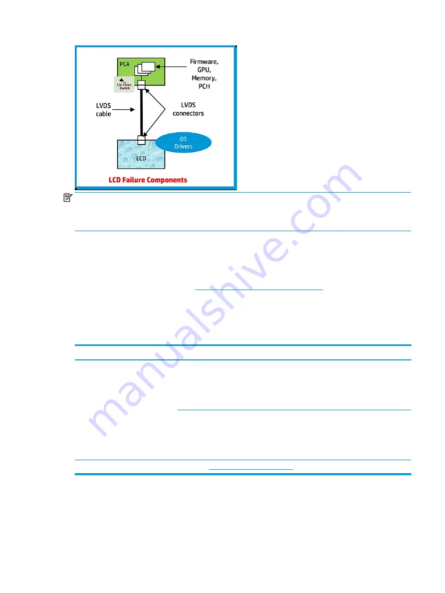
NOTE:
The lid close switch is a Hall-effect sensor located in the top cover. When the display is closed, the
sensor acts like a switch is closed. A notebook can force a video output to an external monitor, or go to
hibernation or standby mode through power management. If the display screen does not light up when the
display is open, the lid close switch (Hall-effect sensor) could be faulty.
Dead pixel
Display panel may show one or more pixels that are not properly lit when displaying a single color over the
screen area. Use HP PC Hardware Diagnostics (UEFI) tool to determine those defective pixels.
There is no solution for dead pixels. See
Display issue: pixel anomalies on page 179
for the HP dead pixel policy.
No video (internal)
Use this information to troubleshoot video issues.
Table 7-28
Issues, possible causes, and fixes
Items
Procedures
Symptoms
No internal video with certain programs
(for example, video-intensive games)
Possible causes
Display resolution, brightness, faulty lid switch, running a program requiring a higher resolution
than the display screen can support.
Faulty lid switch may put the system into Sleep or Hibernation mode.
Troubleshooting steps
Use an external monitor with higher resolution.
Test with external monitor using HDMI or HP port. Press the power button and close the
computer lid to force video output to external video. If there is still no video, contact support.
References
No video (with power) on page 132
for display information.
No video (external)
Use this information to troubleshoot external video issues.
ENWW
Common issues and possible solutions 145
Summary of Contents for ZBook Fury 17 G7
Page 4: ...iv Important notice about Customer Self Repair parts ENWW ...
Page 6: ...vi Safety warning notice ENWW ...
Page 14: ...xiv ENWW ...
Page 23: ...Keyboard area ENWW Keyboard area 9 ...
Page 24: ...Touchpad 10 Chapter 2 Components ENWW ...
Page 32: ...18 Chapter 2 Components ENWW ...
Page 44: ...30 Chapter 3 Illustrated parts catalog ENWW ...
Page 52: ...38 Chapter 4 Removal and replacement procedures preliminary requirements ENWW ...
Page 198: ...184 Chapter 7 Troubleshooting guide ENWW ...
Page 214: ...200 Chapter 11 Specifications ENWW ...
Page 222: ...208 Chapter 12 Statement of memory volatility ENWW ...
Page 226: ...212 Chapter 13 Power cord set requirements ENWW ...
Page 228: ...214 Chapter 14 Recycling ENWW ...
Page 232: ...218 Index ENWW ...