background image

2   How to Install and Upgrade Accessories In Your PC

Installing a Security Cable

64

After installing the new battery, replace the computer’s cover and run 
the 

Setup

 program to reconfigure the computer. You enter 

Setup

 by 

pressing 

F2

 at startup.

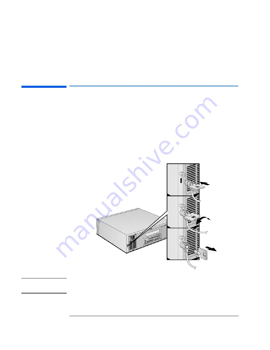
Installing a Security Cable

You can secure the PC to your desk, or any other fixed object, using a 
Kensington

TM

 security cable. The PC has a slot at the rear for securing 

the cable.

1

Insert the lock into the slot located at the rear of the PC.

2

Turn the key to lock the cable to the PC.

3

Remove the key and store it in a safe place. 

NOTE

The Kensington

TM

 security cable is not an HP accessory. It cannot be 

ordered from HP. Contact your reseller for more information.

Summary of Contents for Vectra VEi 7

Page 1: ...Troubleshooting and Upgrade Guide www hp com go vectrasupport Corporate PCs ...

Page 2: ...ed by copyright All rights are reserved No part of this document may be photocopied reproduced or translated to another language without the prior written consent of Hewlett Packard Company AdobeTM and AcrobatTM are trademarks of Adobe Systems Incorporated KensingtonTM is a trademark of Kensington Microware Ltd McAfee VirusScan is a registered trademark of Network Associates Inc Microsoft MS MS DO...

Page 3: ...attery that does not contain heavy metals Nevertheless in order to protect the environment do not dispose of batteries in household waste Please return used batteries to the shop from which you bought them to the dealer from whom you purchased your PC or to HP so they can either be recycled or disposed of in a sound way Returned used batteries will be accepted free of charge If you have a modem Do...

Page 4: ... replace hardware components Service Handbook Chapters information on upgrade and replacement parts including HP part numbers Technical Reference Manual technical information on system components such as system board chipset and BIOS You will also find complete information on available service and support at the HP World Wide Web site To see the full set of services available go to www hp com go v...

Page 5: ... models only 15 If Your Monitor Is Not Working Properly 16 If There Is a Memory Test Error 17 If There Is a Keyboard or Mouse Test Error 18 If There Is a Floppy Disk Drive Test Error 19 If There Is a Hard Disk DVD or CD ROM Test Error 20 If There Is a CMOS Test Error 21 If There Is a Serial or Parallel Port Test Error 22 Other Configuration Problems 23 If You Cannot Turn Off Your PC 24 If You Have...

Page 6: ...Recovering Preloaded Software from a CD ROM 31 Reinstallation of Windows NT Service Pack 32 Changing the Hard Disk 32 BIOS Problems 32 Updating Your PC s BIOS 32 HP Setup Program 33 Device Boot Order 33 More Troubleshooting for Drives 35 If the Floppy Drive Has a Problem 35 If the Hard Disk Has a Problem 36 If the CD ROM or DVD Drive Has a Problem 37 Hewlett Packard Support and Information Service...

Page 7: ... or Adding a Hard Disk Drive 51 Configuring an IDE Device After Installation 54 Installing and Upgrading Removable Media Devices 55 Installing Accessory Boards 57 Accessory Board Slots 57 PCI Slot Numbers Used in the PC s Setup Program 58 Installing an Accessory Board 58 Configuring Accessory Boards with Plug and Play 61 Configuring non Plug and Play ISA Accessory Boards 62 Changing the Battery 63...

Page 8: ...upervisor Password 69 Setting the User Password 69 Hardware Monitoring with HP TopTools 71 Master Pass Key System 72 4 Technical Information System Board Jumpers 74 IRQs DMAs and I O Addresses Used by Your PC 75 Power Consumption 77 Total Power Consumption 77 Physical Characteristics 77 Acoustic Noise Emission 78 ...

Page 9: ...ter can help you solve problems you may have when using your PC Do not hesitate to use the HP DiagTools Hardware Diagnostics utility described on page 10 DiagTools can help you to quickly diagnose hardware problems for a speedy recovery ...

Page 10: ...ectively For more information about this utility refer to the Hardware Diagnostics User s Guide available on the HP web site in PDF Adobe Acrobat format Where Can I Get DiagTools DiagTools is on the Diagnostics Recovery CD ROM that came with your PC You can also download the latest version of this utility from HP s Web Site at www hp com go vectrasupport Starting DiagTools from the CD ROM If you h...

Page 11: ...ne F F F F1 1 1 1 help for information 2 Insert the first floppy disk into the floppy drive the second floppy disk is only necessary if you want to carry out Advanced System Tests 3 Restart the PC 4 Enter the Setup program by pressing F2 at startup then set Plug Play O S in the Main menu to No Press Esc to save the settings and exit Setup 5 The PC will start boot from the floppy disk and automatic...

Page 12: ... CD ROM described on page 10 For HP s support web site connect to www hp com go vectrasupport Documentation For Your PC You can download documentation for your PC free of charge from HP s support web site The documents provided are in Adobe Acrobat PDF format The available documents include User s Guide describes how to set up your PC for the first time and contains quick troubleshooting informati...

Page 13: ...ror Refer to page 19 Hard disk or CD ROM error Refer to page 20 CMOS error Refer to page 21 Serial or parallel port error Refer to page 22 Other configuration problems Refer to page 23 You cannot turn off the PC The PC is frozen in power saving mode Refer to page 24 Problem Solution The PC s clock is not keeping time correctly Refer to page 21 You have forgotten your password Refer to page 25 The ...

Page 14: ...d on do not touch any of the internal components with a screwdriver or other metal instrument None of the internal devices are causing the problem 1 Disconnect the PC s power cord 2 Remove the PC s cover 3 Remove internal power connectors from all internal devices 4 Reconnect the PC s power cord 5 Reconnect the power connectors one by one to the internal devices to see which device is defective 6 ...

Page 15: ...address line1 1 Non HP memory modules are not supported Only HP memory modules should be used Check the memory is correctly installed If the error still occurs replace the module 1 3 4 3 2Eh RAM failure on data bits of low byte of memory bus1 Check the memory is correctly installed If the error still occurs replace the module 1 4 1 1 30h RAM failure on data bits of high byte of memory bus1 Check t...

Page 16: ... and see if it works You may need to update your PC s Basic Input Output System BIOS Create a bootable floppy to update your PC s BIOS Refer to page 32 The PC s integrated video is working 1 Disconnect the power cord 2 Remove the PC s cover 3 Install a known working system board from the same model of PC 4 Reconnect the power cord 5 If the monitor works inform HP Support or your authorized dealer ...

Page 17: ... working memory modules from the same model of PC refer to page 45 4 Close the PC reconnect the power cord and check that the PC boots starts If the PC boots but you still have a problem Run DiagTools Refer to page 10 You may need to update your PC s Basic Input Output System BIOS Create a bootable floppy to update your PC s BIOS Refer to page 32 The system board is working 1 Disconnect the power ...

Page 18: ...e 10 You may need to update your PC s Basic Input Output System BIOS Create a bootable floppy to update your PC s BIOS Refer to page 32 The keyboard mouse are working 1 Switch off the PC 2 Replace the keyboard mouse by known working units 3 Switch on the PC and check it works If the keyboard mouse still does not work The system board is working 1 Disconnect the power cord 2 Remove the PC s cover 3...

Page 19: ... PC 4 Close the PC then switch it on and check it works The floppy is working Insert a known working floppy disk and see if it works If the drive still does not work Run DiagTools Refer to page 10 You may need to update your PC s Basic Input Output System BIOS Create a bootable floppy to update your PC s BIOS Refer to page 32 The drive is working 1 Disconnect the power cord 2 Remove the PC s cover...

Page 20: ...bootable floppy disk Refer to page 10 You may need to update your PC s Basic Input Output System BIOS Create a bootable floppy to update your PC s BIOS Refer to page 32 The drive is working 1 Disconnect the power cord 2 Remove the PC s cover 3 Replace the drive by a known working drive from the same model of PC refer to page 48 4 Close the PC then switch it on and check it works The system board i...

Page 21: ...to page 23 The internal battery is working 1 Set the PC to the correct time refer to the operating system manual 2 Switch off and unplug the PC for an hour 3 Restart the PC and check the time is correct 4 If the time is incorrect replace the PC s battery by a new one refer to page 63 You may need to update your PC s Basic Input Output System BIOS Create a bootable floppy to update your PC s BIOS R...

Page 22: ...o the correct connectors on the back of the PC 3 Switch on the PC and the external devices The correct device drivers are installed Refer to the device documentation You may need to update your PC s Basic Input Output System BIOS Create a bootable floppy to update your PC s BIOS Refer to page 32 If the PC still has a problem Run DiagTools Refer to page 10 The system board is working 1 Disconnect t...

Page 23: ...enter Use Disk Defragmenter or ScanDisk To access these utilities select Programs Accessories System Tools from the Start menu For more hard disk troubleshooting refer to page 36 If the PC still displays an error This suggests the configuration settings are corrupted Restore the default values 1 Turn off the PC and disconnect the power cord 2 Remove the cover 3 Change the position of the jumper on...

Page 24: ... data Move the mouse or press a key to try to wake up the PC If you cannot wake up the PC and you still cannot turn it off using the power button unplug the PC from the power supply PC does not make a buzzing or beeping sound when you press the power button but you are still unable to turn it off That you have saved all data and exited all programs 1 Save all data and exit all programs if you can ...

Page 25: ... the power cord 2 Remove the computer s cover 3 Change the position of the jumper on the Clear Passwords jumper block so that it covers the 2 pins at the other end of the block Refer to System Board Jumpers on page 74 for an illustration showing the use of the Clear Passwords jumper 4 Replace the power cord and restart the computer 5 When the message P P P Pa a a ass ss ss ssw w w wo o o or r r rd...

Page 26: ...eck that the Wake On LAN cable is correctly connected to the system board and to the LAN board Refer to page 60 for more information Refer to the LAN board documentation for instructions about installing and using the LAN board Check that the Power Up Events On External Activity PCI Bus field is set to On in the Setup program s Power menu You need to restart the PC and press the F2 key when Press ...

Page 27: ...message telling you that there is no IRQ Interrupt Request available for the sound board 1 Check that you have followed the installation instructions provided with the sound board 2 Check if the new accessory board supports shared interrupts and if possible implement a shared interrupt refer to the accessory board manufacturer for more information 3 Remove the new accessory board If there is still...

Page 28: ...oo low or no audio at all Check that the microphone specifications meet the requirements of the 16 bit sound components The microphone should be a 600 ohm electret type Humming noise If the power grounding of your audio components is inadequate a humming noise may be generated Plug all devices into adjacent power outlets outlets within 5 cm 2 inches of each other or use line filters Occasional cra...

Page 29: ...hen try launching the software again Reinstall the software If the problem continues contact the software manufacturer s support services Date and time are wrong The date and time can be incorrect for the following reasons The time has changed to or from Summer Time The PC has been unplugged from the power too long and the battery is discharged To change the date and time use your operating system...

Page 30: ...o symbol Not all fonts contain the Euro character For Windows 95 and Windows NT Users Windows NT 4 0 and Windows 95 do not provide integrated support For more information on how to enable support of the Euro symbol refer to Microsoft s web site at www microsoft com windows euro asp Configuring Your Keyboard To configure your keyboard go to Settings Control Panel in the Start menu Double click on K...

Page 31: ...s installed on the PC are not covered by the recovery process Recovering Preloaded Software from a CD ROM You can use the Diagnostics Recovery CD ROM1 to change or reconfigure your operating system reinstall drivers or other factory supplied software components The following paths are available where D is the drive letter assigned to your CD ROM drive D Win95 for Windows 95 CAB files D I386 for Wi...

Page 32: ... on page 51 for information about installing hard disk drives If the replacement hard disk drive is brand new you will need to partition and format the drive Refer to your operating system documentation for information on how to do this BIOS Problems Many problems with your PC can be solved by updating flashing the PC s BIOS Basic Input Output System The BIOS is a set of program routines that give...

Page 33: ... system then manually switch off and then on the PC To Go to the Setup Program To go immediately into the Setup program while the Hewlett Packard logo appears on your display press F2 The Setup program allows you to view and change the configuration of your PC such as the passwords standby power saving mode IRQ settings and boot device order Device Boot Order Boot Menu for the Current Startup NOTE...

Page 34: ...tartup Boot menu while the Hewlett Packard logo appears on your display press Esc Boot Menu for the Default Startup You can also enter the Setup program to change the boot order for all startups To do this go to the Boot Device Priority submenu of the Boot menu in the Setup program accessed by pressing F2 at startup ...

Page 35: ...e The CD ROM drive should be serviced by service personnel only Refer to the label on the CD ROM for power requirements and wavelength This PC is a class 1 laser product Do not attempt to make any adjustment of the laser unit If the Floppy Drive Has a Problem 1 Ensure you are using a formatted diskette and it is inserted correctly 2 Make sure that the Floppy Disk Controller option in the Setup Adv...

Page 36: ...ed by pressing F2 at startup You should see a hard disk drive declared in the IDE Primary Master field 5 Verify that the On Chip Primary IDE and On Chip Secondary IDE fields are enabled in the Advanced menu of the Setup program accessed by pressing F2 at startup 6 Run ScanDisk and Disk Defragmenter to see if they detect a problem with the hard disk drive To access these utilities select Programs A...

Page 37: ...g F2 at startup 5 If you intend to boot on CD ROM place CD ROM before HDD in Setup refer to the Boot Device Priority submenu in the Boot menu group of the HP Setup program 6 Run DiagTools to see if it detects a problem with the drive Refer to page 10 DVD Drive Doesn t Play DVD Video 1 Check that the DVD disk you are trying to play and your DVD drive have the same regional code setting NOTE Your DV...

Page 38: ... or DVD drive during a power failure for example you can use the manual eject button For example to eject a CD ROM using the manual eject button 1 With a thin solid rod such as the end of a paper clip push the CD ROM drive s manual eject button 2 The CD ROM drive door will be released opening slightly Carefully pull it open fully and retrieve the CD 3 To close the CD ROM drive door push it gently ...

Page 39: ... problem occurred Run OK How long has the PC been running normally Recent changes to the PC Have there been any recent changes made to the PC Hardware Configuration Which BIOS version is used The BIOS version is displayed in the Setup program Main menu accessed by pressing F2 during start up Any BIOS parameter changes Did the problem occur after changes were made to the BIOS using the Setup progra...

Page 40: ...1 Troubleshooting Your PC Hewlett Packard Support and Information Services 40 ...

Page 41: ...P drive One or Two Free Front Access Device Shelves CD ROM drive already installed on some models DVD Tape or ZIP drive Main Memory Modules 100 MHz SDRAM only 32 MB kit 64 MB kit 128 MB kit 256 MB kit Main Memory Modules 100 MHz SDRAM only 32 MB kit 64 MB kit 128 MB kit 256 MB kit Up to Four Accessory Board Slots Some slots may come with pre installed boards such as a network adapter Up to Four Ac...

Page 42: ...your eyes by laser light do not open the laser module The laser module should be serviced by service personnel only Do not attempt to make any adjustment to the laser unit Refer to the label on the CD ROM drive for power requirements and wavelength This product is a class 1 laser product CAUTION Static electricity can damage electronic components Turn all equipment OFF Don t let your clothes touch...

Page 43: ...f the monitor and PC disconnect all power cords and any telecommunication cables If necessary unlock the cover at the rear of the PC 1 Undo the three thumb screws at the back of the PC and remove the cover by sliding it towards you by about 2 cm 0 8 inches and then lifting it off 2 If required remove the front panel To remove the panel lift the retaining catches then tilt the panel forwards and li...

Page 44: ...nal cables are properly connected and safely routed 1 If necessary replace the front panel To do this insert the plastic positioning tabs into the holes in the front of the PC chassis and snap the panel in place 2 Lower the cover and slide it into position 3 Tighten the three thumbscrews at the rear of the PC 4 If required lock the cover with the key at the rear of the PC ...

Page 45: ...le you are removing the accessory from the bag Hold the accessory by the edges being careful not to touch the components or connectors You can install up to a total of 512 MB two 256 MB modules Main memory is available in 100 MHz modules of 32 MB 64 MB 128 or 256 MB NOTE You can install a mixture of ECC and non ECC memory modules However if one module is non ECC all modules will behave as non ECC ...

Page 46: ...escribed in this chapter Replacing Video Memory VEi 7 models only VEi 7 models come equipped with 4 MB of video memory in a single slot You can upgrade video memory by replacing the 4 MB module with an 8 MB module 1 Remove the computer s cover described in this chapter 2 To gain access to the video memory slot remove the floppy hard disk drive tray refer to Installing and Upgrading Removable Media...

Page 47: ...ve the old memory module by gently pulling aside the two retaining clips as shown in figure Discard the old memory module 4 Insert the new memory module as shown in figure 5 Reconnect all data and power connectors 6 Replace the drive tray 7 Replace the cover described in this chapter ...

Page 48: ... outlet and any connection to a telecommunication network Always replace the cover before switching the PC on again CAUTION Static electricity can damage electronic components Turn all equipment OFF Don t let your clothes touch the accessory To equalize the static electricity rest the accessory bag on top of the PC while you are removing the accessory from the bag Handle the accessory as little as...

Page 49: ...re you use the correct data and power connectors Power Connectors Number in PC Use for 3 Hard disk drives DVD drives CD ROM drives Zip drives 1 Floppy disk drive Master boot Hard Disk Drive CD ROM CD RW DVD Zip or Hard Disk Drive s Floppy Disk Drive VEi 7 models Floppy Disk Drive Master boot Hard Disk Drive VEi 8 models CD ROM CD RW DVD Zip or Hard Disk Drive s For detailed instructions about inst...

Page 50: ...ation procedures The following table explains which IDE data connectors you should use when you install additional devices Selecting the Bootable Device To select the device to start boot from you must enter the Setup program and go to the Boot Device Priority submenu of the Boot menu You enter Setup by pressing F2 at startup Before Installing an IDE Hard Disk Refer to the drive s installation gui...

Page 51: ...rd disk drive s internal components Make sure that you back up your files before you install a hard disk drive Refer to your operating system documentation for information on how to do this Replacing the Hard Drive To replace the existing hard drive with a new one 1 Remove the computer s cover described in this chapter 2 Remove the drive s data and power connectors 3 Remove the four retaining scre...

Page 52: ...s another device for example a CD RW or Zip drive you must remove it in order to install a second hard drive 1 Remove the computer s cover and front panel described in this chapter 2 Remove any installed devices from the upper and lower expansion bays see Installing and Upgrading Removable Media Devices on page 55 3 Fit the new data cable to the 2ND IDE connector on the system board NOTE HP cannot...

Page 53: ...y and fit the data and power connectors to the hard drive You must use the end black Master data connector 6 Place the four screw holes on the hard drive against the matching screw holes on the base of the PC 7 Attach the four screws 8 Replace any device you previously removed from the upper expansion bay and reattach all connectors You must use the middle white Slave connector to this device ...

Page 54: ...d by pressing F2 at startup Configuring an IDE Device After Installation IDE drives are automatically detected by the Setup program However a newly installed device may require that you install an appropriate device driver Refer to your operating system documentation and the device s manual for details You can obtain the latest drivers from HP s Web site at www hp com go vectrasupport ...

Page 55: ... 1 laser product The PC has an integrated Enhanced IDE controller which supports up to three IDE devices Removable media IDE devices such as CD ROM drives DVD drives tape drives and Zip drives require front access You can install a removable media IDE drive in an empty front shelf 1 Remove the PC s cover and front panel described in this chapter NOTE If your drive is supplied with three retaining ...

Page 56: ...rovided with the device 4 Attach all connectors There may also be a CD or DVD audio cable Illustrations on page 60 show where to connect the audio cable to the system board on your PC 5 Replace the floppy hard disk drive tray if you removed it earlier 6 Replace the PC s front panel and cover described in this chapter Optional third screw Audio connector optional ...

Page 57: ...he static electricity rest the accessory bag on top of the computer while you are removing the accessory from the bag Handle the accessory as little as possible and with care Accessory Board Slots The PC has four accessory board slots The PCI slots can be used for short 32 bit PCI board length up to 17 6 cm or 6 93 inches The ISA slot can be used for a short 16 bit ISA board Accessory Board Connec...

Page 58: ...f you want to change the PCI slot configuration in the Setup program The logical slot numbers are printed on the PC s motherboard Installing an Accessory Board NOTE Only use XT format ISA accessory boards width less than 10 4 cm or 4 1 inches The length of boards you install must not exceed 17 6 cm or 6 9 inches 1 Remove the computer s cover described in this chapter 2 Undo the screw from the slot...

Page 59: ... new board carefully slide it into position then press it firmly into the slot and tighten the retaining screw 4 The accessory board may need a special connection such as Network board to the WOL Wake on LAN connector Sound board to the CD ROM drive if you no longer want to use the integrated audio ...

Page 60: ...the Power Up Events On External Activity PCI Bus field in the Power menu of the PC s Setup program This only applies if the network board supports this mode To enter the Setup program press F2 during startup 5 Replace the cover described in this chapter VEi 7 Celeron equipped models VEi 8 Pentium equipped models WOL connector WOL connector audio connector1 1 If you install an add on sound board re...

Page 61: ...twork adapters and accessory boards Windows 95 and Windows 98 Operating systems that support Plug and Play such as Windows 95 and Windows 98 will automatically detect a newly installed Plug and Play accessory board and install the driver for this device if the driver is available Windows NT 4 0 For operating systems that do not support Plug and Play such as Windows NT 4 0 refer to the operating sy...

Page 62: ...splay the IRQs and I O addresses currently used by your PC Refer to the operating system documentation for more information Refer to the documentation supplied with the operating system for details on your operating system s capabilities and restrictions concerning non Plug and Play accessory boards Resetting the PC s Configuration Data If your PC is having difficulties recognizing the ISA board t...

Page 63: ...used batteries to the shop from which you bought them or to the dealer from which you purchased your PC or to HP so that they can either be recycled or disposed of in an environmentally sound way Returned used batteries will be accepted free of charge You should order replacement battery HP 1420 0356 from your local Sales and Service office or a CR2032 type battery which is available from most loc...

Page 64: ...g a Security Cable You can secure the PC to your desk or any other fixed object using a KensingtonTM security cable The PC has a slot at the rear for securing the cable 1 Insert the lock into the slot located at the rear of the PC 2 Turn the key to lock the cable to the PC 3 Remove the key and store it in a safe place NOTE The KensingtonTM security cable is not an HP accessory It cannot be ordered...

Page 65: ...an order a Master Pass Key lock from an authorized HP reseller and fit it to your PC as follows 1 Remove the cover from your PC described in this chapter 2 Push out the metal disc on the PC s back panel 3 Insert the lock in the hole with the key inside the lock 4 Secure the lock with the metal clip provided 5 Replace the computer s cover described in this chapter 6 Refer to the Master Pass Key Sys...

Page 66: ...2 How to Install and Upgrade Accessories In Your PC Installing a Master Pass Key Lock 66 ...

Page 67: ...3 Security and Manageability Features This chapter explains how to use the security features of your PC such as passwords and hardware monitoring ...

Page 68: ...up of the Setup program Software passwords Operating systems such as Windows NT 4 0 and Windows 95 have a password facility Refer to your operating system documentation for more information Tips for Using Passwords Set a User or Supervisor password to prevent your PC from being started in your absence In addition if you enable Password on Boot in the Setup Security menu you can protect your PC s S...

Page 69: ...sword 1 Enter the Setup program by pressing F2 during startup 2 Select the Security menu group 3 Select the Supervisor Password submenu 4 Choose the Password on Boot item and set it to Enabled 5 Choose the Set Supervisor Password item You will be asked to enter your password twice Save your changes when you exit the Setup program by selecting Exit then Save and Exit To remove the password follow t...

Page 70: ...t a User password 1 Enter the Setup program by pressing F2 during startup 2 Select the Security menu group 3 Select the User Password submenu 4 Choose the Set User Password setup item You will be asked to enter your password twice Save your changes when you exit the Setup program by selecting Exit then Save and Exit To remove the password follow the same procedure as to set a password You will be ...

Page 71: ...hich allows you to view alerts generated by DMI enabled applications such as TopTools and McAfee VirusScan HP TopTools also includes a Crash Monitor module that can be downloaded and installed together with TopTools This module helps you to save your data if an application crashes Since crashes are often caused by low system resources TopTools can send out alerts when these resources are running l...

Page 72: ... administrator to open all machines in an installed base with a single key Refer to page 65 for information on how to install a Master Pass Key lock in your PC The Master Pass Key System can be purchased from any authorized HP reseller If you want to order the Master Pass Key System refer to HP s accessories Web site at www hp com go vectraaccessories ...

Page 73: ...4 Technical Information This chapter provides technical information on your PC For more information refer to the PC s data sheet in the library on HP s web site www hp com desktop ...

Page 74: ...ium Processor The position of system board jumpers on VEi 8 models is shown below Clear CMOS Clear Password Clear CMOS Default Clear CMOS Clear Password Default Clear Passwords Clear CMOS Clear CMOS Default Clear CMOS Clear Password Default Clear Passwords Processor Frequency jumper only required for some processors To install the jumper simply place it over the jumper block It can only go on one ...

Page 75: ...l port if enabled IRQ5 reserved for audio IRQ6 floppy disk controller IRQ7 used by parallel port if enabled IRQ8 real time clock IRQ9 available for PCI devices if not used by ISA board or USB port IRQ10 available for PCI devices if not used by ISA board or USB port IRQ11 available for PCI devices if not used by ISA board or USB port VEi 8 models reserved for USB on VEi 7 models IRQ12 mouse IRQ13 c...

Page 76: ... and 3A8h parallel port 2E8h 2EFh serial port 2F8h 2FFh serial port 370h 371h integrated I O controller 378h 37Fh parallel port 3B0h 3DFh 3B0 3BB 3O0 3DF integrated video graphics controller 3E8h 3EFh serial port 3F0h 3F5h 3F7h integrated floppy disk controller 3F8h 3FFh serial port 678h 67Bh parallel port if ECP mode is selected 778h 77Bh parallel port if ECP mode is selected ...

Page 77: ...tput 36 W Standby Windows 95 98 only 23 W Off 3 W Characteristic Description Weight excluding display and keyboard 8 7 kg 19 pounds Dimensions Width 41 8 cm 16 5 inches Height 14 0 cm 5 5 inches Depth 37 5 cm 14 8 inches Footprint 0 157 m2 1 68 ft2 Storage temperature 40 ºC to 70ºC 40 ºF to 158 ºF Storage humidity 8 to 85 relative non condensing at 40ºC 104 ºF Operating temperature 5 ºC to 35 ºC 4...

Page 78: ... Acoustic Noise Emission Acoustic Noise Emission Measured according to ISO 7779 Sound Power Sound Pressure Operating typical LwA 39 dB LpA 30 dB Operating with HDD access typical LwA 41 dB LpA 32 dB Operating with FDD access typical LwA 46 dB LpA 38 dB ...

Page 79: ......

Page 80: ...lyze the problem Upgrade your PC s BIOS Try using a known working floppy disk Check the floppy drive configuration in Setup Check the drive cable is correctly connected Run the HP Setup program to correct the configuration problem Check power cord is correctly connected Check the device driver is correctly installed Check the device configuration in Setup Clean the mouse ball Check the devices are...

Reviews: