background image

Axles


NOTE

All maintenance and repair works must solely be 

carried out by expert personnel. Safety regula

-

tions must be strictly complied with!

The oil in the wheel gears must be changed at 

regular intervals. Check for leaks on the gears. 

Check the hoses for visible damages.

Remove all dirt from the steering knuckles once 

every day. For this purpose turn steering once 

completely to the left and the right.

Wheel drive

The wheel motor transmits its power to the wheel 

via the wheel gear.

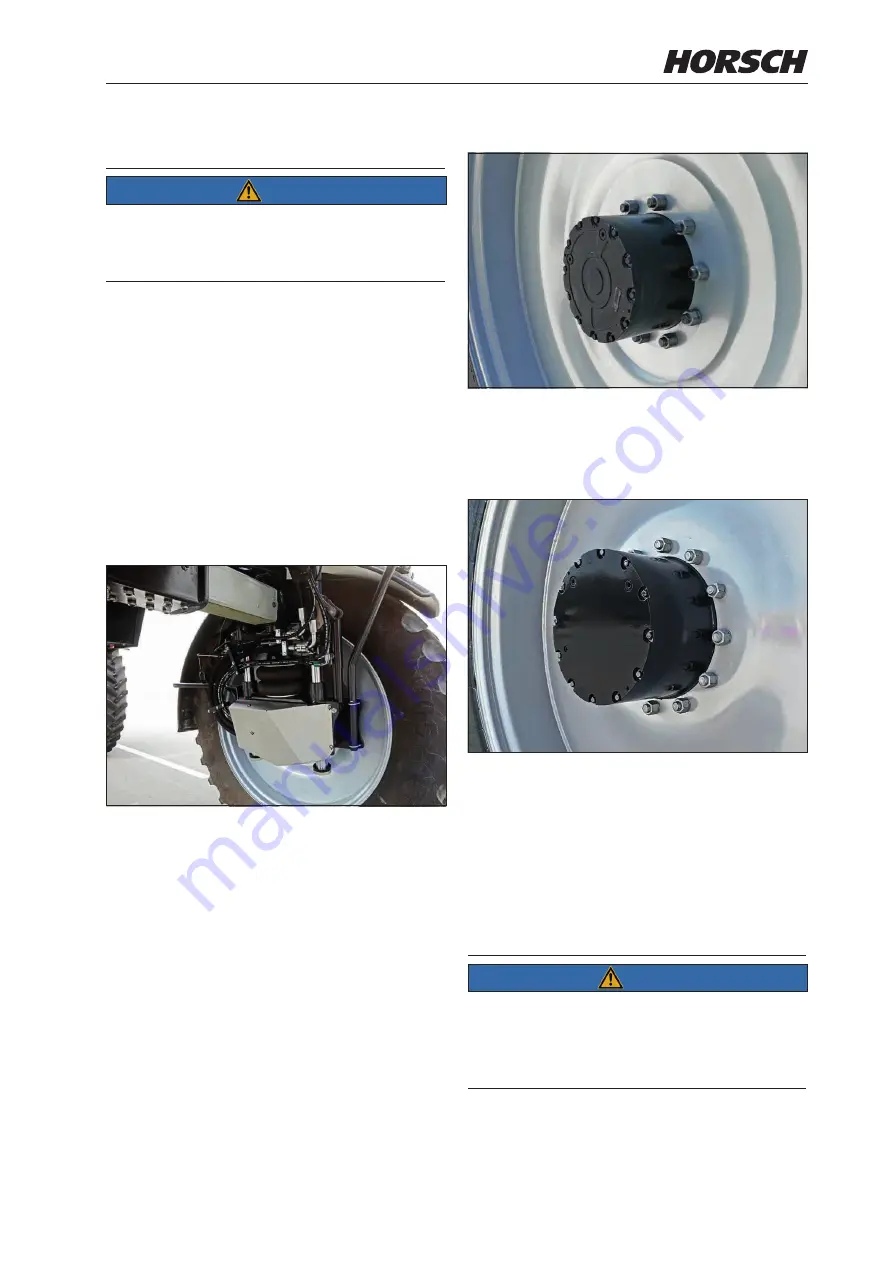
Two gear variants – PowerGear (GFT 8130) and 

HighPowerGear (GFT 8144) – are available. 

PowerGear (GFT 8130)

• 

Small variant

• 

10 wheel nuts

HighPowerGear (GFT 8144)

• 

Large variant

• 

12 wheel nuts

The correct amount of oil in the gears must be 

ensured depending on the variant!

Oil change


NOTE

Change the oil of the wheel gears after the 

first 100 hours and then after every 600 hours. 

Refer also to the 

Undercarriage maintenance over-

view

 section.

70

71

Summary of Contents for Leeb 5.280 VL

Page 1: ...L OPERATING INSTRUCTIONS READ CAREFULLY PRIOR TO STARTING UP KEEP OPERATING INSTRUCTIONS IN A SAFE PLACE ART ISSUE OPERATING INSTRUCTIONS 02 60043155 04 2021 Leeb 5 6 8 280 VL Leeb 5 6 8 300 VL Leeb 5...

Page 2: ......

Page 3: ...9431 7143 9200 E mail info horsch com Customer No HORSCH Confirmation of receipt of machinery Warranty claims become only effective when the first use of the machine is reported to HORSCH Maschinen G...

Page 4: ...hutzspritze Leeb 5 300 VL Leeb 6 300 VL Leeb 8 300 VL Leeb 5 280 VN Leeb 6 280 VN Leeb 5 300 VN Leeb 6 300 VN Translation of EC Declaration of Conformity Directive 2006 42 EC The manufacturer HORSCH L...

Page 5: ......

Page 6: ...Technical Data Leeb 5 280 6 280 VN Variant Emission Standard Stage 3a 37 Technical Data Leeb 5 300 6 300 VN Emission Standard Stage 5 Variant 41 Type plate 45 Dimensions 46 Weight and tyres 47 Attach...

Page 7: ...arter 95 Transport and safety container 96 Tool storage 96 Cabin 97 Access ladder 97 Cabin door 99 Overview 100 Overview roof console 101 Overview roof console 102 Overview roof console A pillar 103 D...

Page 8: ...air filters category 4 optional 140 Radio 145 On Off 145 Multi mode buttons 145 Volume knob 145 Station scan 145 Save radio station 146 Playing media files 146 Software menu 146 Bluetooth 147 Engine...

Page 9: ...ng boom 207 Unfolding 208 Folding in 208 Preparation for spraying operation 209 Preparing the spraying mixture 210 Calculating filling refill quantities 211 Calculating filling refill quantities 212 N...

Page 10: ...for machines of the CCS and CCS Pro variant 262 Outside cleaning optional 263 Care and maintenance 264 Faults 267 Attachment maintenance overview 268 Overview of basic vehicle lubrication points 271 F...

Page 11: ...7...

Page 12: ...ve confirmed proper acceptance of the machine The warranty period starts with the date of delivery The operating instructions were prepared based on the EC Machinery Directive EN Standards and German...

Page 13: ...ress Machine model and serial number Purchasing date and operating hours or area performance Type of problem Warranty claim processing Warranty claim forms must be submitted to HORSCH through your loc...

Page 14: ...must also be complied with The permissible axle loads must not be ex ceeded during road travel Any other kind of use of the machine contradict ing the above are considered not as intended especially...

Page 15: ...the safe opera tion of the vehicle The person knows all applicable road traffic regulations and is in possession of a valid driving permit for road travel A person being instructed must only work wit...

Page 16: ...ve equipment includes e g overall resistant to chemicals protective gloves resistant to chemicals shoes resistant to chemicals face protection safety goggles to protect against splashes Respirator Pro...

Page 17: ...personal abilities carriage way traffic sight and weather conditions In addition pay attention to the notes in chapter Commissioning Safety in operation Commissioning The operational safety of the ma...

Page 18: ...e machine if not in use Replace hydraulic hoses at the latest after six years see Maintenance overview Pressure accumulator The pressure accumulators installed in the hydraulic system are always under...

Page 19: ...ly carry out a brake test Adjustments and repair work on the brake sys tem must only be carried out in a professional workshop or by an operator who has been specially trained by HORSCH for this purpo...

Page 20: ...lity of the machine in case of longitudinal or transverse inclination when working in uneven terrain Observe the limit values of the machine Do not remove any of the mandatory and supplied protective...

Page 21: ...relevant information about the crop protection agents used safety data sheets instructions for use etc in the document compartment The water quality the water hardness and mineral content in particul...

Page 22: ...SCH for this purpose Comply with country specific instructions for weights weight distribution and dimensions For equipment influencing the weight or weight distribution the regulations concerning tow...

Page 23: ...s and bearings When cleaning with high pressure cleaning equipment or steam jets keep a distance of at least 150 cm to machine components After cleaning check all hydraulic lines for leaks and loose c...

Page 24: ...m Danger zone when lifting lowering the folding boom 16 ft 5 m 16 ft 5 m 16 ft 5 m 16 ft 5 m Danger zone with active BoomControl 16 ft 5 m 16 ft 5 m 16 ft 5 m 16 ft 5 m Danger zone with steering all...

Page 25: ...80 6 280 VN 5 300 6 300 VN with permissible tyres and adjusted air pressure Stability Track width wider than 2 60 m 8 5 ft Contour line Without height adjustment or down Height adjustment up Travel di...

Page 26: ...instructions must be read and followed 04002983 Caution for fluids spraying out under high pressure follow the notes in the operating instruc tions 04001682 Do not open or remove protec tive features...

Page 27: ...eep sufficient distance to elec tric high voltage power lines 04002983 Secure the machine with wheel chocks before uncoupling or parking 04002983 Before commissioning the ma chine the operating instru...

Page 28: ...ng mix ture container 04004094 Switch over ball valve Inside outside clean ing only for machines with outside cleaning option 60016560 60016560 Lower the undercar riage completely be fore folding or u...

Page 29: ...kers with the addition 2x can be found on either side of the machine 60016560 1 1 2E05598 50 x 96 mm 2 5 mm 00385738 2014 07 29 gelb schwarz CX4 he Draisstra e 19 a b 76461 Muggensturm 00385738 on all...

Page 30: ...Safety stickers with the addition 2x can be found on either side of the machine Position of safety stickers depending on equipment on all diaphragm accumulators on all 4 wheel suspensions 00000000 26...

Page 31: ...he hydraulic functions are possible without additional installation Pneumatic level suspension only Leeb VL To minimise the transport height the folding boom for the level suspension may have been unh...

Page 32: ...connections and hoses for correct fastening and function Immediately rectify any occurring damage or have it corrected Assemble the wheels WARNING Use only approved tyres as specified in the technical...

Page 33: ...weight on road PowerGear High PowerGear 18 000 20 000 kg 40 000 44 000 lbs 18 000 20 000 kg 40 000 44 000 lbs 18 000 20 000 kg 40 000 44 000 lbs max total length in trans port position 11 7 m 460 in...

Page 34: ...neumatic suspension Steering Front axle hydraulic Rear axle hydraulic electric automatic centring and interlocking for road travel Steering modes only front axle steering all wheel steering auto matic...

Page 35: ...on height pump height max working pressure 8 bar 116 psi Working speed 4 32 km h 2 5 20 mph Solution tank Spraying mixture container rated volume 5000 l 1 300 gal 6000 l 1 600 gal 8000 l 2 100 gal Act...

Page 36: ...arance 300 2800 mm 11 110 in Jet height at 2 0 m 78 in ground clearance 700 3200 mm 28 125 in All dimensions and weights depend on boom width tyres and equipment Information depending on selected tyre...

Page 37: ...s Curb weight 13000 14500 kg 28 600 32 000 lbs 13000 14500 kg 28 600 32 000 lbs 13000 14500 kg 28 600 32 000 lbs max perm total weight on road PowerGear High PowerGear 18 000 20 000 kg 40 000 44 000 l...

Page 38: ...road Transmission hydrostatic infinite Speeds Field 0 25 km h 0 15 mph Folding boom folded in 0 32 km h 0 20 mph Folding boom unfolded Road 0 40 km h 0 25 mph 0 50 km h 0 31 mph Drive permanent all wh...

Page 39: ...Three phase alternator 12 V 200 A Starter 12 V 4 kW Attachment Sections min max piece Pulse width modulation Single nozzle control Pneumatic nozzles 6 42 Working height 300 2800 mm 12 110 in Centrifu...

Page 40: ...ob computer Jet height at 1 6 m 62 in ground clearance 300 2800 mm 11 110 in Jet height at 2 0 m 78 in ground clearance 700 3200 mm 28 125 in All dimensions and weights depend on boom width tyres and...

Page 41: ...28 600 32 000 lbs max perm total weight on road Power Gear HighPowerGear 18 000 20 000 kg 40 000 44 000 lbs 18 000 20 000 kg 40 000 44 000 lbs max total length in transport position 11 7 m 460 in 11 7...

Page 42: ...tic suspension Steering Front axle hydraulic Rear axle hydraulic electric automatic centring and interlocking for road travel Steering modes only front axle steering all wheel steering auto matically...

Page 43: ...ar psi suction height pump height max working pressure 8 bar 116 psi Working speed 4 32 km h 2 5 20 mph Solution tank Spraying mixture container rated volume 5000 l 1 300 gal 6000 l 1 600 gal Actual v...

Page 44: ...e 300 2800 mm 11 110 in Jet height at 2 0 m 78 in ground clearance 700 3200 mm 28 125 in All dimensions and weights depend on boom width tyres and equipment Information depending on selected tyres Dri...

Page 45: ...ete filling of the machine Machine type 5 300 VN 6 300 VN Chassis Curb weight 13000 14500 kg 28 600 32 000 lbs 13000 14500 kg 28 600 32 000 lbs max perm total weight on road Power Gear HighPowerGear 1...

Page 46: ...ansmission hydrostatic infinite Speeds Field 0 25 km h 0 15 mph Folding boom folded in 0 32 km h 0 20 mph Folding boom unfolded Road 0 40 km h 0 25 mph 0 50 km h 0 31 mph Drive permanent all wheel dri...

Page 47: ...12 V 180 Ah Three phase alternator 12 V 200 A Starter 12 V 4 kW Attachment Sections min max piece Pulse width modulation Single nozzle control Pneumatic nozzles 6 42 Working height 300 2800 mm 12 110...

Page 48: ...idth tyres and equipment Information depending on selected tyres Driving is possible on these slopes but restrictions must be expected regarding technical residue placement of the residue emptying of...

Page 49: ...s number Model designation Engine power System pressure sprayer Volume spraying mixture container Capacity fresh water tank Year of construction Empty weight Total weight permissible axle load front a...

Page 50: ...75 11656 11656 4300 4300 NOTE Deviations due to technical further development reserved The dimensions may vary depending on the machine equipment and design of the folding boom The weight of the machi...

Page 51: ...total weight can be taken from the following tables Flange dimension Leeb VL narrow base frame 2 67 3 57 m Leeb VL wide base frame 3 07 4 17 m Leeb VN 2 32 3 07 m NOTE The specifications reflect the...

Page 52: ...si 12941 lbs 11530 lbs 10780 lbs 4 8 bar 6180 kg 5510 kg 5150 kg 70 psi 13625 lbs 12148 lbs 11354 lbs Alliance 350 380 105 R50 Load index 168 D Pressing depth 35 Air pres sure Speed Permissible total...

Page 53: ...psi 14352 lbs 14352 lbs 14352 lbs 3 6 bar 6900 kg 6900 kg 6900 kg 52 psi 15212 lbs 15212 lbs 15212 lbs Mitas HC 2000 VF 380 105 R54 Load index 168B Pressing depth 35 Air pres sure Speed Permissible to...

Page 54: ...14606 lbs 14606 lbs 14606 lbs 3 6 bar 7300 kg 7300 kg 7300 kg 52 psi 16094 lbs 16094 lbs 16094 lbs Alliance Agriflex 354 VF 480 80 R50 Load index 171D Pressing depth 0 Air pres sure Speed Permissible...

Page 55: ...3228 lbs 13228 lbs 13228 lbs 2 2 bar 6900 kg 6900 kg 6900 kg 35 psi 15212 lbs 15212 lbs 15212 lbs Alliance Agriflex 354 VF 520 85 R46 Load index 170D Pressing depth 15 Air pres sure Speed Permissible...

Page 56: ...968 lbs 10450 lbs 10020 lbs 1 6 bar 5465 kg 5205 kg 4990 kg 23 psi 12048 lbs 11475 lbs 11001 lbs Alliance Multistar 376 620 70 R46 Load index 162A8 Pressing depth 65 Air pres sure Speed Permissible to...

Page 57: ...wheels Leeb VL with wheels without wheels 0 8 bar 5645 kg 5535 kg 5535 kg 3 75 m 3 10 m 148 in 122 in 4 15 m 3 49 m 163 in 137 in 12 psi 12445 lbs 12203 lbs 12203 lbs 1 0 bar 6465 kg 6340 kg 6340 kg...

Page 58: ...ights 13 Battery 5 Diesel engine 14 Cooler package 6 Fuel tank right side of machine 15 Air filter 7 Hydraulic oil tank 16 Air conditioning system 8 Maintenance access 17 Windscreen washing system 9 W...

Page 59: ...culation of the machine must contain mineral based hydraulic oil Oil purity acc to ISO 4406 18 16 13 Always connect all hydraulic lines Otherwise components may get damaged because of interrelated fun...

Page 60: ...nly be switched on with the ignition activated 3 4 Front headlamps for driving light and high beam each on the right and left side 3 High beam 4 Parking light daytime running light dimmed headlight 5...

Page 61: ...ach on the right and left side optional Rear light reversing light brake light and blinker hazard light system each on the right and left side The design may vary according to the country WARNING Traf...

Page 62: ...schrauben nachziehen 00380359 Fehler Keine Referenz Allgemein toleranz Horsch Maschinen GmbH nderungen sind untersagt Landwirtschaft aus Leidenschaft HORSCH Maschinen GmbH Sitzenhof 1 92421 Schwandorf...

Page 63: ...t be started The oil level should always be between the min and max marks on the dipstick The oil level can be read from the dipstick left side of the engine NOTE Maintaining the required oil level is...

Page 64: ...Wet the rubber seal of the new filter with clean oil Tighten the filter quickly until it is just seated Now turn the filter by another half turn NOTE Change the engine oil and the engine filter after...

Page 65: ...cooling liquid Clean cooling system Always keep air intakes and cooling nets clean Shut the engine down for cleaning If necessary clean with compressed air or a water jet NOTE The cooling fins of the...

Page 66: ...lity and cleanliness of fuel and carbonyl diamide solution are of fundamental importance for continuous good performance and a long service life of the engine Always refuel every day after the end of...

Page 67: ...and drink plenty of water Do not induce vomiting Change soiled clothes immediately In case of allergic reactions consult a physi cian immediately Keep fuel or carbonyl diamide solution away from chil...

Page 68: ...onyl diamide solution Carbonyl diamide filter change only with Leeb 5 6 8 300 VL and Leeb 5 6 300 VN Unscrew the lid of the carbonyl diamide filter Figure FPT Remove the plunger of the filter Figure F...

Page 69: ...erating hours or annually Vent the system after changing the filter Ventilation Fill the fuel tank with fuel Open the vent screw Pump with a hand pump until fuel escapes from the vent screw without f...

Page 70: ...Hydraulic oil tank The tank is located on the right hand side of the machine Oil level inspection Fold in the spraying boom Set the hydraulic height adjustment to street level optional Shut down the...

Page 71: ...you should strictly consult the Customer Service Refer to the Maintenance chapter and the HORSCH maintenance log for the first oil change and the further intervals Place a suitable collecting vessel...

Page 72: ...housing 2 Take out the filter 3 Replace the seal ring 4 Reinsert the new filter 5 Assemble the housing cover 6 Check the filter for leak tightness with the engine running Hydraulic oil filter NOTE Yo...

Page 73: ...s against rolling before releasing the brake WARNING Danger of crushing cutting being pulled in being caught and impact caused by incorrectly functioning brake system Perform a function test of the br...

Page 74: ...e parking brake In this case the parking brake can be released manually Press in the tappet 1 on the hydraulic pump Operate the hand pump 2 until a noticeably resistance can be felt The parking brake...

Page 75: ...ring once completely to the left and the right Wheel drive The wheel motor transmits its power to the wheel via the wheel gear Two gear variants PowerGear GFT 8130 and HighPowerGear GFT 8144 are avail...

Page 76: ...gearbox note the value in cm Gear PowerGear GFT 8130 approx 3 5 cm 1 38 in Gear HighPowerGear GFT 8144 approx 3 5 cm 1 38 in Open the filler plug and fill in new oil up to the lower level 3 5 cm Fille...

Page 77: ...drop too low when cool ing down Repair work on tyres must only be carried out by experts and by using appropriate as sembly tools Assembly work requires appropriate knowl edge and proper tools 510 Nm...

Page 78: ...lves Tighten the wheel screws with 510 Nm 375 ft lb Execution 1 Park the machine on a level and paved area 2 Apply the parking brake 3 Place the jack on the side of the wheel to be changed at the lift...

Page 79: ...ust have a lifting capacity of at least 5 tons NOTE Lower the machine completely Leeb VL Disengage the linkage for the level suspension This must be done separately for each axle and each wheel All 4...

Page 80: ...0 5 300 6 300 8 300 VL Depending on the equipment and variant of the vehicle the track width can be set be tween 2 60 to 4 47 m 102 to 176 in Leeb 5 280 6 280 5 300 6 300 VN Depending on the equipment...

Page 81: ...ne axle with the lifting equipment Always loosen the mounting screws of the sliding axle from the inside to the outside Loosen from the inside to the outside the figure shows the left rear axle lower...

Page 82: ...echanical Pre clamping 40 Nm 30 ft lb after clamping 80 Nm 60 ft lb Hydraulic Pre clamping 40 Nm 30 ft lb after clamping 80 Nm 60 ft lb Tighten the hexagon nuts with 180 Nm 133 ft lb Pay attention als...

Page 83: ...r and the fresh water tank 2 3 4 Wheel suspension mechanical height adjustment the figure shows the left front 1 Locking screw detail 1 2 Retaining plate Height adjustment up procedure Drain the spray...

Page 84: ...lifting equipment Screw in the three locking screws 1 to secure the joint Tightening torque 64 Nm 47 ft lb Reinsert the retaining plate 2 to secure the rod 3 and tighten with screws Tightening torque...

Page 85: ...spension ComfortDriveFlex Refer again to the Commissioning section for this purpose Leeb VL The pneumatic independent suspension in cludes a level control independent of the load condition Level valve...

Page 86: ...he machine Leeb VN The hydropneumatic suspension includes an au tomatic level control independently of the load condition Operation is done via the machine terminal Follow the Terminal operating instr...

Page 87: ...e Mechanical release device folding boom block parallelogram and Load Sensing activation In case of faults of the parallelogram lift for release of the folding boom block and for Load Sensing activati...

Page 88: ...hoot ing Fan In the event of an electrical defect of the valve on the hydraulic venting device cooling of the engine the hydraulics the charge air and the A C system will no longer work and the machin...

Page 89: ...e for hydraulic track width adjustment TrackControl optional In the event of an electrical defect a release device for hydraulic track width adjustment optional for the directional release is located...

Page 90: ...installed DANGER Severe accidents by crushing Ask all persons to leave the danger zone when lowering Mechanical release device hydropneumatic suspension only Leeb VN In the event of an electrical defe...

Page 91: ...f the platform can be folded down or up by hand It is imperative when working in the maintenance area to fold up the folding boom in the interest of one s own safety The railing must be folded down to...

Page 92: ...ke system must only be carried out with the engine shut off and cooled down Pay attention to possibly contaminated dust in the filter Do not inhale it and avoid skin contact Do not blow out or suction...

Page 93: ...housing cover a and remove the lid 2 Push the main element b at a slight angle of 5 towards the front 3 Remove the main element b 4 Remove the safety element c NOTE Never wash out or brush off the mai...

Page 94: ...Refrigerant NOTE The air conditioning system is operated with the refrigerant R134a tetrafluoro ethane This substance does not contain any chlorine atoms and is thus harmless for the ozone in the atmo...

Page 95: ...on Pressure switch The air conditioning system is equipped with a pressure switch which switches the system off in case of overpressure or vacuum This is attached to the dryer cartridge Dryer cartridg...

Page 96: ...een washing system tank It is recommended to add a windscreen washing agent to achieve a better cleaning effect NOTE Drain the washing system in the winter or use windscreen cleaner with appropriate f...

Page 97: ...k whether the filter regulator combination is empty Drain them manually if necessary NOTE The dryer cartridge must be changed if water has collected in the air reservoir Compressed air system dryer ca...

Page 98: ...ical system right behind the cabin Danger when handling batteries CAUTION Only perform repair care maintenance and cleaning work with the machine at standstill Shut down the engine Pull out the igniti...

Page 99: ...huts itself off The exhaust gas treatment optional keeps running for an other 15 minutes until final shut down Three phase alternator Always disconnect the battery main switch before starting work on...

Page 100: ...Transport container on the right side of the machine Transport container on the left side of the machine WARNING To avoid contamination of the cabin it must not be entered with used protective outfit...

Page 101: ...clean at all times folding access ladder 1 2 Multi function control panel Access ladder foldable via pushbuttons on the multi function control panel in the cabin keep button depressed Button 1 access...

Page 102: ...eed of 3 km h 1 9 mph or more is reached The green square indicates that the setting is active 1 If function 2 is activated the ladder moves down automatically as soon as the machine is in the parking...

Page 103: ...cabin door must be kept closed before driv ing off and throughout operation Unlock with the key press the button and pull on the handle Door handle from outside Press the door opener lever up Door ha...

Page 104: ...hine terminal 6 Pedal 7 Driver s seat 8 Instructor s seat 9 Central electrics of machine 10 Tray document box 11 Monitor for rear view camera optional NOTE Do not store any pointed heavy objects on th...

Page 105: ...17 18 12 Operating elements Heating air conditioning system 13 Adjustment of the electric outside mirror 14 Switching driving lights on off 15 Switching work lighting on off 16 Switching rotating bea...

Page 106: ...9 Storage compartment 20 Switch for hazard light system 21 Switch for road travel field travel 22 Travel drive warning lamp 23 Switch for parking brake 24 Cabin lighting and reading lamp 25 Circulatin...

Page 107: ...Overview roof console A pillar 29 29 30 30 27 27 29 29 27 Circulating air filter 28 adjustable fan nozzle 29 Radio loudspeakers 29 29 29 103...

Page 108: ...table fea tures during operation WARNING Danger to persons in case of accidents by not wearing seat belts Always wear your seat belt before commis sioning the vehicle After an accident the seat belts...

Page 109: ...y reached the height will be automatically adapted to ensure a minimum suspension travel NOTE To avoid damage operate the compressor for max 1 min Horizontal suspension a b Under certain operating con...

Page 110: ...should be locked against being moved to any other position Do not lift the locking lever with your leg or calf Seat inclination adjustment The inclination of the seat area can be individu ally adjuste...

Page 111: ...n be changed by turning then hand wheel Turning towards the outside lifts the armrest at the front turning towards the inside lowers it at the front Backrest adjustment Pull the lever up to adjust the...

Page 112: ...e back of the back rest is equipped with a stowage bag To open the stowage bag first pull the tab up and then open the lid of the stowage bag back wards Seat belt Both the driver s and the instructor...

Page 113: ...rive Apart from this no other person except the driver must remain on the machine or inside the driver s cabin during op eration of the machine in the field The safety belt must always be fastened Ins...

Page 114: ...heel by hand Operate the lever a at the rear end with your foot With the lever a actuated swivel the steering column by hand to the desired position Release lever a The desired position is now locked...

Page 115: ...intervals A clear vision is mandatory for safe driving Replace the wiper blades at the latest after one year In case of dirty windscreen operate the wind screen washer system before wiping Do not ope...

Page 116: ...e the direction indicator at the front and rear of the machine Lever up direction indicator to the right Lever down direction indicator to the left High beam To operate the high beam press the multi f...

Page 117: ...ing information is shown on the display a b c d e f a Direction indicator lamp Machine b Direction indicator lamp Trailer c High beam indicator lamp d Generator indicator lamp e Main warning lamp f En...

Page 118: ...f the setting is correct release the lever again The multifunction control panel must lock into this position The desired position is now locked Height adjustment NOTE When the lever is pulled up the...

Page 119: ...adjustment suspension in slope mode on off optional 8 Lift access ladder 9 Lower access ladder 10 Height adjustment transport service position only with hydraulic height adjustment 11 Freely assignabl...

Page 120: ...aulic height adjust ment and when the parking brake is engaged Brief push of button The machine lowers to service mode The height adjustment is driven all the way down The spring accumulators remain f...

Page 121: ...The following operating modes are available Automatic temperature and fan control Ideal for high outdoor temperatures Manual fan control Automatic temperature control with manual setting of the fan sp...

Page 122: ...pressing the Minus key 5 The temperature can be increased by press ing the Plus key 7 1x pressing corresponds to 1 C or 1 F The climate control automatically regulates the cabin temperature to the set...

Page 123: ...ose upper fan nozzles b Open lower fan nozzles c completely Align the blades of the fan nozzles c with the footwell Activate ECON mode In ECON mode the air conditioning compres sor is switched off The...

Page 124: ...ve the injury treated immediately by a specialist WARNING Incorrect handling of refrigerant may result in death or serious injury Only have work on the air conditioning sys tems carried out by a quali...

Page 125: ...r filter Evaporator in cabin roof is soiled Clean the evaporator Evaporator defective Have the evaporator replaced by qualified personnel Condenser in front of the water cooler soiled Clean the conden...

Page 126: ...rked blue F1 A blow out temperature sensor error is indicated by the flashing display Switching outputs are switched off The control unit is no longer ready for operation Check system for cable break...

Page 127: ...mage to the air con ditioning system operate the air conditioning system regularly 3 5 Switch on the diesel engine and let it run on idle Open all fan nozzles Open both doors Switch on REHEAT mode 3 t...

Page 128: ...e used However this should be discussed with the HORSCH Service before use NOTE Instructions for operating the terminal are in cluded in the supplied operating instructions Instructions for operating...

Page 129: ...chine The door for it can be opened completely or only a gap Open door completely Pull the lever forward and push the window open The window can be opened completely NOTE The emergency exit cannot be...

Page 130: ...n as far as necessary Pull the sun visor downwards as far as necessary Pull the cord to open the sun visor again Hold on to the sun visor Pull the cord to loosen the sun visor CAUTION If the spring me...

Page 131: ...and off with the switch Storage compartment with integrated cooling function under the seat area of the instructor s seat Storage compartment There is a document storage compartment under the driver s...

Page 132: ...while driving NOTE Do not open the monitor housing since the function is otherwise no longer ensured Main tenance and assembly work may only be carried out by qualified personnel The machine can optio...

Page 133: ...s can be shown on the camera image The position of the markings can be adjusted horizontally and or vertically and their spacing can be changed Name camera name can be freely defined e g Front Mirrori...

Page 134: ...the connected vehicle signals active high the assigned view is activated when voltage is applied to the trigger input active low the assigned view is activated when no voltage is applied to the trigg...

Page 135: ...e roof console Switch for adjusting the outside mirrors Turn switch to left or right to select the side of the outside mirror Turn the switch up down and to the side until the outside mirror is optima...

Page 136: ...e figure shows emission standard stage 5 machines with emission standard 3a have a different vehicle socket for engine diagnostics 4 1 Vehicle socket outlet for engine OBD diagnostics 2 Vehicle socket...

Page 137: ...itself off The ex haust gas treatment optional keeps running for another 15 minutes until final shut down NOTE When performing maintenance work on the vehicle electrical system or the battery the ve...

Page 138: ...20 A Not used F026 20 A Not used F027 10 A Not used F028 30 A Not used F029 10 A Not used F030 20 A Rotating beacon relay output F031 3 A Not used F032 10 A Not used F033 10 A Not used F034 7 5 A Not...

Page 139: ...ly RC20 10 30 Master Slave F055 3 A Supply charging indicator light rotary encoder steering wheel F056 10 A Engine control unit supply terminal 15 No Amperage Function F057 10 A Armrest supply termina...

Page 140: ...30 A Engine control unit supply terminal 30 F096 35 A Relay supply ATS K049 exhaust gas treatment F097 5 A Diagnostics plug supply FPT terminal 30 F098 15 A Forced ventilation supply terminal 15 No Am...

Page 141: ...he fuses for the pulse width modulation PrecisionSpray are located in the middle section of the folding boom under the black coverings If several nozzles fail at the same time check the function of fu...

Page 142: ...amaged filters Reinstall air recirculation grille Fresh air filter category 2 NOTE The activated carbon filter must be replaced every 3 months regardless of the operating hours The pocket filter must...

Page 143: ...arbon filters into the pocket filters Attach the pocket filters with the activated carbon filters again Close the covering Activated carbon filter with pocket filter WARNING If the air filter is incor...

Page 144: ...s cleaned by one or more filter stages and freed from dust aerosols or gases The filter system has an integrated fan which transports the fil tered fresh air into the cabin At the same time a certain...

Page 145: ...ters Dust filter Empty frame Maintenance NOTE The activated carbon filter must be replaced every 3 months regardless of the operating hours The dust filter and aerosol filter must be replaced after 6...

Page 146: ...en the lid 2 of the filter box Depending on the maintenance interval remove the filter in the order dust filter 3 aerosol filter 2 activated carbon filter 1 Clean the housing with a moist cloth Check...

Page 147: ...products with the symbol 1 in household waste at the end of their useful life Recycle used materials with the symbol 2 according to their identification Recycle and reuse packaging materials and do no...

Page 148: ...sure required for cabin filtering category 4 a warning message is displayed on the machine terminal Pressure monitoring is controlled on the ma chine terminal Select Cabin Filter Cat 4 Settings in the...

Page 149: ...mode On Off Briefly press the power button to turn on the unit Press and hold the power button for one second to turn it off Multi mode buttons In radio mode stations can be stored here In media mode...

Page 150: ...select Radio Media or AUX If media is connected to both slots the last slot played is played back Use the left and right arrow keys to scroll through the individual music files The F and F keys can be...

Page 151: ...ile phone After successful pairing most mobile phones can automatically re establish the Bluetooth connection the next time the radio is switched on Calls can be accepted via the button with the green...

Page 152: ...Ensure sufficient ventilation Requirements for motor start Main battery switch for power supply The main battery switch for the power supply is located at the right side of the cabin below the ignitio...

Page 153: ...2 before the engine is started wait with the next starting attempt until the engine has come to a stop In this case turn the ignition key first to position 1 and then repeat the attempt Shut down the...

Page 154: ...n the road and in the field to the prevailing conditions Reduce the travel speed when driving down hill Do not exceed the permissible angles of incline Refer to the section Use on hillside locations I...

Page 155: ...r of the drive lever Drive lever release button Move the drive lever forward to select the direction of travel and set the machine in motion Drive lever The drive lever returns to middle position when...

Page 156: ...n motion Reverse driving NOTE When reversing the operator must make sure that no persons are about in the danger zone The machine may only travel backwards with the assistance of a guide when persons...

Page 157: ...eversed by press ing the release button and simultaneously mov ing the driving lever to the left This means that the vehicle will not stop at 0 mph 0 km h but will automatically change the direction o...

Page 158: ...safety distances depend ing on load and speed Drive slippage control The self propelled machine comes with fully automatic drive slippage control ASR NOTE Manual intervention in difficult terrain is n...

Page 159: ...eering is deactivated automatically When driving slower again than 9 mph 15 km h the driver must reactivate rear axle steering Field operation When field mode is activated rear axle steering can be sw...

Page 160: ...riving the vehicle the driver takes on full responsibility and must always pay attention to the current traffic situation Cruise control settings can be made and changed through the terminal or with t...

Page 161: ...cient stability and tipping over Adjust the personal travel mode in such a way that you will at any time have control over the vehicle Be aware of your own abilities account for the road traffic sight...

Page 162: ...eering mode Towing must in any case be performed only with the help of a towbar Three point hitching should in any case be used for towing Example of three point hitching Remote start jump start The s...

Page 163: ...me of the vehicle the engine should be switched off on both vehicles When starting from a different source first switch on the assisting vehicle and then the receiving vehicle It is recommended that t...

Page 164: ...rn the knob to navigate to the individual symbols There the values can be changed in the submenu A function can be selected by pressing the rotary knob Press the ESC key to return to the main screen R...

Page 165: ...22 23 24 25 26 27 28 29 30 31 32 33 34 17 Hydraulics temperature 18 Hydraulic pressure of the travel drive 19 Air pressure 20 Engine utilisation 21 Engine temperature 22 Fuel consumption 23 Level of...

Page 166: ...d right 10 Filling connections 4 Hand washing tank 11 Storage compartment right and left machine side 5 Spraying pump 12 Maintenance access 6 Piston diaphragm pump 13 Outside cleaning right side of ma...

Page 167: ...ed during spraying and vented during filling The internal cleaning nozzles clean the spray ing mixture container with fresh water after the spraying process The agitator mixes the spraying mixture ins...

Page 168: ...ccess Dome DANGER Danger of injury by poisonous vapours Do not climb into the spraying mixture container Dome The dome is fitted with a sieve to prevent the ingress of impurities when the spraying mix...

Page 169: ...CCS Pro The filling port is located to the left of the illuviation valve Filling port The ventilation for the fresh water tanks is lo cated in the centre between spraying mixture container and engine...

Page 170: ...e required quantities Spraying pump The pump used does not require pulsation damping because centrifugal pumps generate continuous flow and pressure The spraying pump installed in this machine is near...

Page 171: ...w spray ing pumps Slight formation of oil drops on the pump housing may occur until the mechanical seal has been broken in Check the oil level of the pump regularly and top it up if necessary Piston d...

Page 172: ...ition 4 Switching fitting for canister flushing closed circuit flushing line shock nozzle and washing gun 5 Switch over ball valve for sucking off and connecting external filling devices 6 7 8 9 10 11...

Page 173: ...on 18 during operation Press the handle to release After switching off 9 relieve the residual pressure NOTE Depending on the position of the ball valve of the suction side water exits from the fresh w...

Page 174: ...switch off the inside surface of the pressure filter insert is constantly flushed and undissolved spraying agent and dirt particles are caught in the dome screen when the chemical is returned to the...

Page 175: ...cleaning nozzle is installed to facilitate clean ing of the dome screen Suction filter The suction filter filters the water chemical before the piston spraying pump mesh size 0 9 mm Different mesh siz...

Page 176: ...f suction and pressure valves Basic yes no mechanical CCS yes yes mechanical Basic Pro yes no electric CCS Pro yes yes electric Operation For machines with the Basic and CCS equipment operation takes...

Page 177: ...Off button Pressing the Switch spraying pump On Off button again deactivates the pump When the filling mode is active the filling func tion can be deactivated at the main terminal on the filling side...

Page 178: ...ainer residue drain 2 Spraying mixture container pressure output 3 Filling port for fresh water tank External control terminal External control terminal Mini 1 2 3 1 Switching the spraying pump On Off...

Page 179: ...ner 8 9 10 8 Pressure filter locking lever 9 Pressure filter flushing drain 10 Suction filter drain valve Mechanical 6 way valve pressure side 5 1 2 3 4 1 Filling the spraying mixture container 2 Inte...

Page 180: ...ulation off Suction stirring illuviation valve pulling suction wash program pressure informa tion fresh water recirculation high pressure cleaner outside cleaning winter storage Refer also to the info...

Page 181: ...container residue drain 2 Spraying mixture container pressure output 3 Filling port for fresh water tank External control terminal External control terminal 1 2 3 4 5 6 7 7 1 Confirm and accept chang...

Page 182: ...e switch over ball valves Switching between internal and outside clean ing Pressure filter flushing intensity with mechani cal pressure filter flushing Selection Spraying mixture container filling cle...

Page 183: ...residual quantity in the spray ing mixture container the agitator can also be completely disabled CCS agitator The spraying mixture container is equipped with a hydraulic agitator Special injector no...

Page 184: ...residual quantity in the spray ing mixture container the agitator can also be completely disabled CCS Pro agitator The spraying mixture container is equipped with a hydraulic agitator Special injecto...

Page 185: ...n 9 Folding boom rest WARNING Staying under the raised folding boom is pro hibited Danger of crushing and impact for persons when lifting or lowering for height adjustment of the spraying boom Instruc...

Page 186: ...Folding variants Folding boom 5 piece with reduced working width 17 m 17 m 55 ft 30 36 m 100 ft 120 ft NOTE With a 5 piece folding boom 17 36 partial folding is not possible 182...

Page 187: ...ptionally smooth sur faces such as e g water puddles the ultrasonic signal may be reflected The control must in these areas be deactivated BoomControl does not relieve the driver from his responsibili...

Page 188: ...of the folding boom via mid dle section height guidance and independent bending of both folding boom halves controlled by 4 sensors distributed over the entire folding boom Transport lock WARNING The...

Page 189: ...arallelogram lock The stroke of the parallelogram must always be locked during road travel The parallelogram is locked automatically as soon as the folded fold ing boom is in the end position of the r...

Page 190: ...linders that are locked or unlocked via lock valves Uniform transverse distribution is only achieved with the slope compensation unlocked NOTE Before starting road travel make sure that the folding bo...

Page 191: ...individual sections or the entire spraying line for the first time the biocata lytic solution is directly and well mixed available This circulation successfully prevents the forma tion of deposits an...

Page 192: ...nnection 4 the valve will open and fluid can flow out Without pressure the valve is closed 1 2 3 4 5 6 7 8 1 Nozzle body 2 Diaphragm 3 Pneumatic control valve 4 Compressed air connection 5 Bayonet con...

Page 193: ...out pressure the valve is closed 1 2 3 4 5 6 7 8 1 Nozzle body 2 Diaphragm 3 Pneumatic control valve 4 Compressed air connection 5 Bayonet connection 6 Rubber seal 7 Bayonet cap 8 Nozzle Multiple nozz...

Page 194: ...d install them Use the delivered tool for this purpose Cleaning nozzles Clean the nozzles if required Do not damage nozzles and nozzle filters when cleaning CAUTION CAUTION Spraying mixture running ou...

Page 195: ...triple nozzle body manually 1 1 with triple nozzle body manually Design of pulse nozzle switching valves 1 2 3 4 5 6 1 O ring 2 Outlet seal 3 Valve body 4 O ring 5 Valve piston with closing spring 6...

Page 196: ...11005 4 bar 58 psi Application quantity 150 l ha 16 gal ac Travel speeds from 5 4 to 18 km h 3 3 to 11 mph at the same pressure and the same placing quantity At 10 km h 6 2 mph application quantities...

Page 197: ...nal Orange The GPS receiver can receive GPS signals but the differential signal is absent Accuracy is therefore very low Green The GPS receiver receives GPS sig nals and differential signals Installat...

Page 198: ...e connecting cable of the GPS receiver to it 1 Switch off the terminal 2 Route the connecting cable of the GPS re ceiver into the vehicle cabin 3 Connect the connecting cable to the RS232 port on the...

Page 199: ...Vehicle GPS antenna calibration With standard tyres VF520 85 R46 Tyre radius 915 mm Track width 195...

Page 200: ...0 4300 3000 906 2147 FA 2543 2777 0 4300 3000 906 2147 6 300 VL PE 2543 2827 0 4300 3000 906 2147 FA 2543 2777 0 4300 3000 906 2147 8 280 VL FA 2543 2852 0 4300 3000 906 2147 8 300 VL FA 2543 2852 0 4...

Page 201: ...All main and auxiliary nozzles remain in use Border nozzle If an edge nozzle is activated via the terminal with 1 fold nozzle bodies level 1 of the first or last main nozzle is switched off with 2 fo...

Page 202: ...eaning is automatically enabled when switch ing off the nozzles e g at the headland With each cycle the pump sucks in fresh water through a filter for approx 4 seconds At this the pump delivers approx...

Page 203: ...in The filling pump can be started stopped via the control terminal Direct filling connection with pump and filter optional NOTE The wet seal chamber for the radiator antifreeze must always be filled...

Page 204: ...Outside cleaning is supplied with fresh water via the centrifugal pump With standard water system depending on the valve position WARNING Danger through accidental contact with spray ing mixture Wear...

Page 205: ...ed To fix the handle actuation press the tappet during operation Press the handle to release After switching off relieve the residual pres sure High pressure cleaner optional 1 2 3 High pressure clean...

Page 206: ...Sensor measures the chlorophyll and adjusts the placing quantity accordingly N Sensor bracket NOTE The bracket only fits the Yara N Sensor Series ALS Safety package optional Warning triangle safety v...

Page 207: ...y to movements of equipment which are continuous or automatically controlled or require a floating or pressure position because of their function Prerequisites for the suitability of the machine are i...

Page 208: ...tion NOTE Make sure before driving on public roads that the machine meets all respective applicable national road traffic regulations NOTE Check the following prior to road travel the light system for...

Page 209: ...ft right slope compensation 5 Lift left slope compensation 6 Add sections to left 7 Add sections to right 8 Switch off sections to right 9 Switch off sections to left 10 Application quantity 5 optiona...

Page 210: ...is activated all active sections or border edge nozzles are enabled When the main switch 4 is deactivated all active sections or border edge nozzles are in the preselected state Pay attention to the...

Page 211: ...possibly also fatal injuries Keep a sufficient safety distance to moving parts of the machine as long as the engine is running Make sure that persons keep a sufficient safety distance to moving parts...

Page 212: ...ing process is carried out at a travel speed greater than 5 km h 3 1 mph and the folding boom is not secured an alarm message is displayed on the terminal and the folding process stops automatically B...

Page 213: ...sizes of pressure filters and nozzle filters must always be smaller than the nozzle opening of the nozzles used Notes given by the manufacturer of the crop protection agent must be followed The stand...

Page 214: ...risks as low as possible e g thoroughly wash off and dispose of used gloves Dispose of washing water and cleaning fluid in a proper manner NOTE Besides the generally valid information listed hereunde...

Page 215: ...A 1 5 kg ha x 2 5 ha 3 75 kg Product B 1 0 l ha x 2 5 ha 2 5 l Example 2 Addition of product area The following is known Rated tank volume 1000 l Residual quantity in tank 200 l Required water 500 l h...

Page 216: ...roduct B 0 11 gal ac x 6 18 ac 0 67 gal lqd Example 2 Addition of product area The following is known Rated tank volume 264 gal lqd Residual quantity in tank 53 gal lqd Required water 53 5 gal ac Reco...

Page 217: ...7 7 29 30 31 32 34 35 36 295 90 22 24 25 7 27 29 30 8 5 32 34 35 36 38 40 41 328 100 24 27 28 8 30 32 33 9 5 36 38 39 40 42 44 45 656 200 48 54 56 15 8 60 64 66 19 72 76 78 80 84 88 90 984 300 72 81 8...

Page 218: ...asurement of the crop protection sprayer Procedure The tables apply to 50 cm nozzle spacing Nozzle sizes and colour coding acc to ISO 10625 With diagram and universal table 1 Determine application qua...

Page 219: ...Diagram a with example 215...

Page 220: ...lication quantity l ha Nozzle output l min Nozzle size Universal table b with 50 cm nozzle spacing with example The values apply for water of 20 C pressure measured directly at the nozzle Check the va...

Page 221: ...or the line s with the required plac ing quantity use approximate values if necessary 4 Read nozzle size pressure and nozzle output Example 1 Placing quantity Travel speed 200 l ha 8 km h 2 See placin...

Page 222: ...Colour Type Colour Pres sure bar Pres sure bar l min l min Placing quantity in l ha at km h Placing quantity in l ha at km h Universal table with 50 cm nozzle spacing with example The values apply fo...

Page 223: ...ersal table with 20 in nozzle spacing with example The values apply for water of 68 F pressure measured directly at the nozzle Check the values with a measuring vessel before the start of application...

Page 224: ...9 psi 8 0 bar 116 psi ID all sizes 2 bar 29 psi 8 0 bar 116 psi Air Mix nozzles all sizes 1 bar 14 psi 6 0 bar 87 psi IDK IDKN all sizes 1 bar 14 psi 6 0 bar 87 psi TTI all sizes 1 bar 14 psi 6 0 bar...

Page 225: ...221...

Page 226: ...Fluid circuit Design of water system Basic and water system CCS 6 42 43 44 45 4 5 1 3 2 7 8 9 10 13 21 20 19 18 16 12 22 23 24 25 26 27 29 11 38 38 28 14 17 33 32 15 41 30 31 34 35 36 37 39 40 222...

Page 227: ...tional 21 Filter NightLight outside cleaning optional 22 Suction filter with drain valve 23 Centrifugal pump 24 Spraying pump pressure sensor 25 External pressure output 26 Mechanical 6 way valve on p...

Page 228: ...5 1 2 8 9 10 13 12 23 26 28 224...

Page 229: ...nal pressure Variant 2 When filling the solution tank via port 10 the pressure valve 26 can be set to the illuviation valve At the same time set the valve 28 to fresh water filling CAUTION Filling via...

Page 230: ...26 39 40 42 43 45 226...

Page 231: ...in position b so that the wash flows through the circulation system back into the spraying mixture container This prevents the formation of deposits Wash is immediately available at the nozzles when...

Page 232: ...uit Design of Water system Basic Pro and water system CCS Pro 44 1 2 3 4 5 6 7 8 9 10 11 12 13 14 15 16 17 18 19 20 21 22 23 24 25 26 27 28 29 30 31 32 33 34 42 38 39 40 35 36 37 41 43 50 45 44 46 47...

Page 233: ...tank filling optional 26 Piston diaphragm pump only with CCS Pro 27 Suction filter piston diaphragm pump only with CCS Pro 28 Switch over ball valve fresh water suction aid only with CCS Pro 29 Filte...

Page 234: ...44 1 2 5 8 9 10 16 25 12 14 230...

Page 235: ...al suction on the external control terminal Switch on the illuviation valve when the remaining solution was displaced by the lines into the spraying mixture container Turn the valve 25 to fresh water...

Page 236: ...44 50 45 44 47 48 232...

Page 237: ...8 is in position b so that the wash flows through the circulation system back into the spraying mixture container This prevents the formation of deposits Wash is immediately available at the nozzles w...

Page 238: ...erating instructions for the crop protection agent to be used Before each filling check the crop protection sprayer for damage e g leaking tanks and hoses as well as the correct positioning of all ope...

Page 239: ...valve can be sucked empty 7 Close the filling valve 8 Uncouple the suction hose 9 Close the connection with the cap Water systems Basic Pro and water system CCS Pro The national laws and relevant regu...

Page 240: ...g hose 2 Open the filling valve 3 Fill the spraying mixture container 4 Close the filling valve 5 Uncouple the hose 6 Close the connection with the cap Direct filling external filling with pump option...

Page 241: ...latform Dome Dome screen and dome cleaning nozzle NOTE The dome screen must be checked daily and cleaned as necessary Filling the fresh water tank through the filling port WARNING Avoid impermissible...

Page 242: ...Always have a sufficient amount of fresh water on board when using the crop protection spray er When filling the spraying mixture container check and refill also the fresh water tank 238...

Page 243: ...on the illuviation valve Crop protection agent and carbonyl diamide are poured into the illuviation valve dissolved and drawn in Swing the illuviation valve down by pulling it by the handle Flush the...

Page 244: ...ball valve 5 again The process may need to be repeated if the required preparation could not be filled in during a single process 10 Pre clean the illuviation valve with the rins ing nozzles 4 11 Open...

Page 245: ...to be repeated if the required preparation could not be filled in during a single process 9 Pre clean the illuviation valve with the rinsing nozzles 4 10 Open the switch over ball valve 5 and have th...

Page 246: ...10 Set the pressure side valve to circulation stirring 11 Adjust the desired agitator power Flushing in liquid preparations with full or partly filled spraying mixture container Water systems Basic P...

Page 247: ...he illuviation valve on the termi nal again 11 Top up the water shortfall 12 Adjust the desired agitator power Flushing in powdery preparations and carbonyl diamide Water systems Basic and CCS NOTE Ex...

Page 248: ...nozzle when the pressure plate is pressed down Canister cleaning with fresh water NOTE Cleaning the canisters with fresh water dilutes the spraying mixture concentration 1 Open the lid on the illuviat...

Page 249: ...ing with fresh water NOTE Cleaning the canisters with fresh water dilutes the spraying mixture concentration 1 Open the lid on the illuviation valve 2 To be able to use clean water for illuviation the...

Page 250: ...t use this for preliminary cleaning Thoroughly clean if clear water is availa ble e g before preparing the next spraying mixture container filling or when diluting the residual quantity of the last sp...

Page 251: ...a slow travel speed and a low spray ing pressure to prevent losses by windward drifting See also chapter Nozzle selection Apply additional measures for windward drift reduction at wind speeds of 3 m s...

Page 252: ...luid volume The higher the spraying pressure the smaller the drop diameter of the sprayed spraying mix ture The smaller droplets are subject to higher undesired windward drift Increasing the spraying...

Page 253: ...e cor responding valve Water systems Basic Pro and CCS Pro The intensity of the agitator can be adjusted via the terminal Switch on the agitator via the terminal The required agitating power depends o...

Page 254: ...time are of the same type and the same size The minimum target area distance corre sponds to half the minimum target area distance for a corresponding 50 cm 20 in nozzle pitch see nozzle manufacturer...

Page 255: ...OTE Drainage output can be controlled with the ball valve If the valve is fully open the pump delivers with full output via the pressure output 2 Switch on the circulation on the terminal 3 Drain the...

Page 256: ...41 m 134 ft Draining technical residual quantities NOTE Make sure that the residual quantity in the spraying line will be sprayed out in the form of undiluted concentration Spray this residual quanti...

Page 257: ...Dilute the residual quantity in the spraying mixture container with 200 litres 52 gal of fresh water 3 Spray the diluted residual quantity also on an untreated residual area 4 Repeat steps 2 and 3 fo...

Page 258: ...truction is not followed Draining the fresh water tank Port for water systems Basic and CCS fresh water tank Port for water systems Basic Pro and CCS Pro fresh water tank The port of the fresh water t...

Page 259: ...lly after cleaning with a high pressure cleaner steam jet or when using grease dissolving cleaning agents Pay attention to the statutory regulations concerning the handling and waste disposal of clean...

Page 260: ...should be done in the field Dispose of any cleaning residues in an envi ronmentally friendly manner each time after cleaning the crop protection sprayer Disassemble the spraying nozzles at least once...

Page 261: ...1 2 1 Folding boom circulation 2 Pressure filter drain valve NOTE Clean the thread of the filter housing if soiled Pressure filter cleaning of water systems Basic Pro and CCS Pro 1 Switch off the fol...

Page 262: ...roperly 5 Insert the cleaned new filter again and close the filter housing with the lid Close the lock valve again 6 Turn the suction side valve to the desired position NOTE Clean the thread of the fi...

Page 263: ...lear water through the internal cleaning nozzles into the spraying mixture container The spraying pump sucks in this water and uses it to force the chemical residue through the nozzles out of the pipe...

Page 264: ...le bodies all existing nozzles must be cleaned There is danger of deposits if this instruction is not followed Washing program for machines of the Basic and CCS variants 1 Fill the fresh water tank wi...

Page 265: ...boom with air optional 16 Repeat steps 1 15 for a second time if necessary a third time dilution principle 17 Cleaning suction and pressure filters Cleaning with filled spraying mixture container NOT...

Page 266: ...out process of water systems Basic Pro and CCS Pro 1 Air reservoir of the machine must be filled 2 Switch off all spraying functions Switch off pressure agitator internal cleaning injector and sprayi...

Page 267: ...changing the crop protection agent before winter storage before care maintenance of the machine 1 Switch off all spraying functions 2 Turn the switch over ball valve to outside cleaning 3 Turn the suc...

Page 268: ...ontamination with crop protection agents Perform all maintenance work on the crop protection sprayer only after cleaning it NOTE Regular and proper maintenance will keep the crop protection sprayer fo...

Page 269: ...rilling on the undercarriage enlarging existing boreholes on the vehicle frame welding on load bearing parts Conversions affect specifications in the op erating instructions NOTE Before each commissio...

Page 270: ...ubricating so that no dirt is pressed into the bearings Press the used up grease completely out of the bearings and replace it with fresh grease Lubricants NOTE A lithium saponified multi purpose grea...

Page 271: ...lves on suction and pres sure side replace if necessary The required and en tered application quan tity is not reached High travel speed low pump drive speed Clogged nozzles nozzle filter or suction f...

Page 272: ...ny work on the hydraulic system Depressurise the hydraulics Empty the pressure accumulators Allow hydraulic oil and hydraulic components heated during operation to cool down before any work on the hyd...

Page 273: ...g joints for zero clearance apparent faults and wear In case of play or lose components have faults corrected by HORSCH Service staff 50 h Folding boom Check setting yearly Safety installations Lighti...

Page 274: ...d lubricate 2 per suspension 10 h or daily Hydropneumatic suspension only Leeb VN lubricate 2 per suspension 50 h or weekly Steering lubricate 1 per suspension 50 h or weekly Pendulum frame central fr...

Page 275: ...Overview of basic vehicle lubrication points Suspension bridge Suspension bridge hydraulic height adjustment Suspension sled Hydropneumatic suspension only Leeb VN 271...

Page 276: ...Steering Mechanical track width adjustment Hydraulic track width adjustment rear underside Hydraulic track width adjustment front top side 272...

Page 277: ...Folding boom 5 piece double folding Outside wing collision protection Inside wing outside wing Middle section inside wing 273...

Page 278: ...hen the folding boom is unfolded or the paral lelogram is raised or lowered Pendulum frame central frame connection Central frame Inside wing middle frame connection Parallelogram to central frame con...

Page 279: ...Central frame middle frame tractor link arm Parallelogram lock 275...

Page 280: ...ction sprayer the standard value is 2 100 pulses 100 l Example The numerical values in the example were randomly chosen and may differ from practice Machine with 36 m working width Setting on terminal...

Page 281: ...is 2 100 pulses 26 gal lqd Example The numerical values in the example were randomly chosen and may differ from practice Machine with 120 ft working width Setting on terminal 2 100 pulses 26 gal lqd S...

Page 282: ...ssure output 8 Close the pressure output with the cap Flow meter test To test the flow meter the test adapter set order number 36960072 can be ordered from HORSCH 1 Disconnect the hose union to the fl...

Page 283: ...essary Check the function and leak tightness of the hydraulic system and water system In use Hydraulics WARNING Lock all hydraulically operated parts before any work on the hydraulic system Depressuri...

Page 284: ...cartridge 2400 or 2 years Drain air reservoir daily Check the filter regulator combination daily Engine Check the oil level daily Check oil filter 100 h Replace fuel prefilter inspection glass 600 h o...

Page 285: ...ter 100 h following adjustment Locking nut 180 Nm 133 ft lb hydraulic Pre clamping 40 Nm 30 ft lb after clamping 80 Nm 60 ft lb Locking nut 180 Nm 133 ft lb After 100 600 1200 2400 h etc Height adjust...

Page 286: ...brake lines and hoses for damages crushing points and kinks daily Check for leaks 200 h Safety installations Lighting and warning boards Check condition and function daily Warning and safety stickers...

Page 287: ...ering cylinder cotter pins Figure varies depending on the machine design Clamping dimension of height adjustment from top edge of suspension bridge to the end covers of the guide column 410 mm 16 in l...

Page 288: ...m approx 4 l 1 gal fill up to max level Hydraulic system oil change quan tity with max filling approx 100 l 26 gal Hydraulic oil HVLP D46 Cleanliness class ISO 4406 18 16 13 after 1200 oper ating hour...

Page 289: ...ipstick or other fluid measuring facilities is decisive for the amount to be filled in Time limited by the value reached first Approved brand designations as far as determined See current list of fuel...

Page 290: ...Hydraulic cylinders must extend and retract without jerking Danger zones must be blocked off during commissioning When performing installation work raised machine parts must be lowered completely mov...

Page 291: ...or seals damaged or poorly fitted O rings brittle or deformed O rings or seals foreign objects loose hose clamps Assembly and disassembly of hydraulic hoses NOTE Use only original spare hoses from HO...

Page 292: ...Drain air reservoir Lower the height adjustment optional NOTE Make a note of all service and maintenance work that has to be done before the start of the next season and place a corresponding order w...

Page 293: ...Properly dispose of the collected residual spraying mixture Fresh water tank 1 Remove the cap on the connection for fresh water filling and open the ball valve 2 Allow the fresh water to drain 3 Clos...

Page 294: ...output to drain the connection Filling ports of water system Basic and water system CCS Filling ports of water systems Basic Pro and CCS Pro Machines with filling pump optional Open the cap and fillin...

Page 295: ...eze agent into a suitable col lection vessel via the residue drain Residue drain of water system Basic and water system CCS Winter storage 1 Depending on the desired frost protection fill the appropri...

Page 296: ...of ensuring that no more antifreeze mix is present in the crop protection sprayer Let the existing cleaning programs run several times with fresh water Completely lubricate the machine as per lu brica...

Page 297: ...t nozzles for the application of liquid fertiliser is beneficial if the liquid fertiliser is to enter into the plant through the roots rather than through the leaf The nozzle orifice integrated in the...

Page 298: ...4 61 233 3 661 300 0 189 86 61 233 3 677 307 5 194 88 63 242 2 692 314 1 198 90 66 250 0 709 321 7 202 92 67 255 7 723 328 3 207 94 69 261 2 740 335 8 211 96 70 266 7 755 342 7 216 98 71 272 0 771 350...

Page 299: ...6 24 33 37 50 54 73 63 86 10 1 25 21 28 26 35 39 53 58 78 67 91 12 1 75 34 46 41 56 64 86 94 127 110 148 12 1 25 37 50 46 62 70 95 103 139 120 163 14 2 00 54 73 66 90 101 137 148 201 173 235 14 1 50 5...

Page 300: ...71 1 220 0 298 3 280 0 380 0 315 0 427 0 7 8 22 2 130 0 176 3 145 0 196 6 320 0 433 9 350 0 474 5 450 0 610 0 500 0 678 0 1 25 4 190 0 257 6 205 0 278 0 480 0 650 8 530 0 718 6 675 0 915 2 750 0 1 017...

Page 301: ...ase spraying pressure Nozzle selection and control The fluid level which indicates the placing quantity in l ha on one side of the HORSCH Leeb metering cup shows at the same time on the other side of...

Page 302: ...nut 190 Blow out process 262 Bluetooth 147 BoomControl 183 205 BoomControl modes 183 Brake 203 Brakes 153 Brake system 15 69 204 282 C Cabin 97 282 Cabin air filtering category 4 140 Cabin door 99 Ca...

Page 303: ...Examples for filling refill quantities 211 212 Exhaust gas system 63 Expansion valve 90 External control terminal 162 External filling 236 F Fan nozzle 103 Fan setting 118 Fan speed 117 118 Fault 120...

Page 304: ...93 Liquid preparations 242 Load bearing capacity 47 Longitudinal adjustment 106 114 Lubrication points 270 Lumbar support 107 M Machine terminal 100 124 154 155 160 Maintenance 18 69 268 279 Maintenan...

Page 305: ...quantity 210 213 Refrigerant 90 Refrigerant R134a 90 REHEAT mode 117 119 Release button 151 152 153 Remedy 120 Residual area 213 Residual quantities 252 Residual quantity 32 36 40 44 252 253 Residue d...

Page 306: ...ernator 95 Tight fit of wheel nuts 73 Tool bracket 96 Tool storage 96 Top speed 13 Total length 29 33 37 41 Towing 158 TrackControl 78 Track width 76 Traffic 12 Transport 27 Transport height 29 33 37...

Page 307: ......

Page 308: ...tions and pictograms are approximate and for information only Subject to technical product revisions HORSCH LEEB Application Systems GmbH Kleegartenstra e 54 94405 Landau a d Isar Tel 49 9951 6041 0 F...

Reviews: