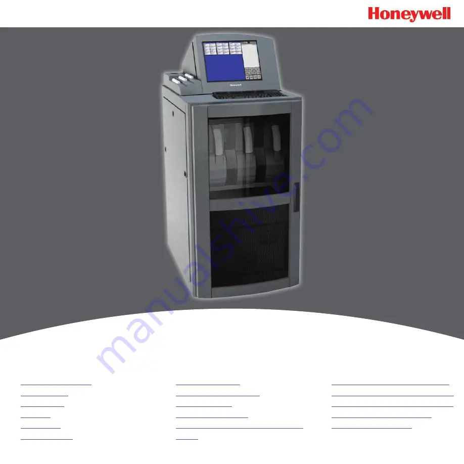
Summary of Contents for Vertex M

Page 1: ...n Installation Startup Operation Maintenance Troubleshooting Installation Drawings Specifications Detectable Gases Replacement and Consumable Items Optional Relay Specifications Network Interface and Options 4 20mA Analog Output Option Line Integrity Test Option Warranty Statement ...

Page 2: ...rances slipping tripping hazards minor corrosive dangers Also used when defining personal protective equipment gloves dust masks etc WARNING Personal injury risk machinery hazards around guarded equipment moving parts crush pinch hazards flying debris and arc flash hazards DANGER The most dangerous or potentially lethal hazards unguarded equipment confined space entrances and lockout labels Cautio...

Page 3: ...e In addition ensure local electrical code requirements are met The following cable parameters must be considered Braid Must have a minimum 90 coverage Foil When used with braid provides 100 coverage Do not use foil alone It has a tendency to break Twisted Pair Provides for cancelling of magnetic fields Stranded Pair Provides the greatest surface area Shield Termination Continuation of the shield ...

Page 4: ... System 1 17 Data Acquisition Computer 1 17 Programmable Logic Controller 1 17 Table of Contents Installation 2 1 Introduction 2 2 Surveying the Installation Site 2 2 Placement of the Vertex M System 2 2 Exposure to Dust and Humidity 2 2 Sample Transport Time 2 2 Instrument Dimensions 2 2 Sample Locations 2 2 Sample Line Particulate Filter Use 2 3 Optional Floor Mounting 2 3 Installing Sample Line...

Page 5: ...eyboard 4 12 Stopping Project 4 12 Review Functions 4 12 Event History 4 13 Data Trend 4 20 Optional ChemCam 4 22 Event List 4 24 Menu Buttons 4 26 Run Time Options 4 26 Flow Calibration 4 32 Maintenance 4 40 Diagnostics 4 41 Service 4 44 Security Access 4 47 Configuration 4 48 OnScreen Keyboard 4 48 Restore OnScreen Keyboard 4 48 Maintenance 5 1 Introduction 5 2 Maintenance Schedules 5 2 Chemcass...

Page 6: ...lyzers D 2 Pyrolyzers D 3 Rack Systems D 3 Power Distribution Module D 3 Pump Modules D 3 Optional Relay Specifications E 1 Relay Output Contacts E 2 Relay Contact Ratings E 2 Default Relay Assignments E 3 Introduction E 3 Main PLC E 3 Terminal Assignment of 1746 OW16 Relay Module E 3 Terminal Assignment of 1746 OX8 Relay Module E 4 Network Interface and Options F 1 Network Interface and Options F...

Page 7: ...unt F 25 Create Group VertexDCOMUsers F 25 Disable Windows Firewall F 27 Configure DCOM F 27 Windows Firewall F 32 Create matching Windows Accounts F 33 Demonstrating Remote OPC Communication F 34 Setup Procedure F 34 Demonstration with Matrikon OPC Explorer F 35 Demonstration with DAClient F 38 4 20mA Analog Output Option G 1 Overview G 2 Hardware Requirements G 2 Configuration Requirements G 2 O...

Page 8: ...1 1 Vertex MTM 24 Point Continuous Monitor Vertex M TM Technical Handbook 1 Introduction ...

Page 9: ...ent analyzer modules allow one to stop monitoring with no effect on the remaining modules Power supplies are redundant Pumps are redundant The system powers up in the same state as when powered down Filters Chemcassettes and major components in one of the analyzers can be replaced while the remaining analyzers continue to function Operation can be through an LCD touch screen or through a local are...

Page 10: ...uction 1 3 1 2 1 Vertex M Front Pyrolyzer Analyzer Universal Chemcassette Analyzer Touch Screen Relay PLC behind monitor See Relay Options or Network Interface Options System Controls Analyzer Front Sample Tubing Exhaust and Wiring Ports Analyzer Side Panel ...

Page 11: ...MTM 24 Point Continuous Monitor Section 1 Introduction 1 4 1 2 2 Vertex M Back Pyrolyzer step up Isolation transformer Back of Pyrolyzing Chemcassette Analyzer Data Acquisition Computer rear 4 20mA Option PLC ...

Page 12: ... pipe thread Alarm Wiring Conduit Plate 2 in 50 8mm Analyzer 2 Sample Ports Analyzer 3 Sample Ports Analyzer 1 Sample Ports Points 1 thru 8 Left to Right 3 Port Manifold for multiple gas sampling Power Connection Access Panel See Section A 4 Nominal Transport Times for tubing length limitations Note The Alarm wiring conduit plate must remain in place if not used ...

Page 13: ...or Section 1 Introduction 1 6 1 2 4 Analyzer Side Panel Exterior View Slide Latch Access Screws Internal View Analyzer CPU ChemCam Option Sample Pressure Transducers Sample Flow Transducers Sensor Interface PCB Proportional Valve Filters ...

Page 14: ...Front 1 2 6 System Controls Power Distribution Module Rack Power Switch and Circuit Breaker Data Acquisition Computer DAq Hot Swap Hard Drives 24VDC Power Supplies CD RW Drive Analyzer DC and Pyrolyzer AC Power Switches with Indicators Analyzer Status LED 2 3 Pyrolyzer Analyzer Slot ...

Page 15: ...C this port only LCD video Serial interface for touchscreen COM 1 Serial Com2 not used Speakers not used Microphone not used External Ethernet USB Chemcam 3 ports USB Host Device Caution Restrict access to the USB port to reduce the risk of malicious software being introduced Note This photograph shows a typical port configuration Port and slot locations vary from model to model ...

Page 16: ... 9 1 2 8 Back of Chemcassette Module ChemCam USB Connection Optional Analyzer Communications Ethernet Analyzer 24V Power Supply Multi Function Connector Cable Carrier Circular Tubing Harness Note Connection secured by slide latch Push up to open Push down to close ...

Page 17: ...tor Section 1 Introduction 1 10 1 2 9 Main PLC Advanced Interface Converter PLC Power Supply DH485 Link Coupler PLC Processor Module Optional Relay Modules DH485 RS232 Interface Module Expansion slot for optional Communications Interface ...

Page 18: ...Vertex MTM 24 Point Continuous Monitor Section 1 Introduction 1 11 1 2 10 4 20mA Analog Output Option PLC Power Supply 4 20mA Output Modules 6X ...

Page 19: ...ation Maintenance Remove and Replace Chemcassette Analyzer Particulate Filters Change Chemcassette Tape Diagnostics Service Alarm Test Fault Test 4 20 mA Test Authorized Service Security Access Configuration Utility Project Functions Define Gas Location Configure Analyzers and Points Set Analyzer Window Configure Point Define and Assign Relays Profile Management File Menu Other Menu Log In and Log...

Page 20: ... lines from sample locations As they apply to the Vertex M System the words point line and location require definition A location is a place to be monitored Sample atmosphere runs from the location to the Vertex M System via a line Each of the 24 sample tubing connections on the Vertex M System corresponds to a point A sample line can be connected directly to a single point or multiple points via ...

Page 21: ...e data acquisition computer Components of the detection system include Chemcassette detection tape Optics and electronics for the detection system Chemcassette tape transport mechanism Self adjusting proportional valves 1 6 1 Detector Optics The heart of the Chemcassette module is an optical detection system that measures a stain that develops on the Chemcassette tape in the presence of a target g...

Page 22: ...ation RFID tag to automatically identify the following Serial number Gas family tape type Revision level Expiration date of the tape Chemcassette leader parameters The module uses a leader on the Chemcassette tape to allow calibration of the optics every time a new tape is installed This feature can be bypassed 1 6 4 Optional ChemCam The ChemCam is a small video camera located between the take up ...

Page 23: ...Analytics for a complete list Charcoal filters have a part number P N 1874 0139 unique to the pyrolyzer module The Vertex M Pyrolyzer requires two adjacent slots on one tier and always occupies Slot 1 and 2 The bottom rail and latch must be removed from slot 1 to install pyrolyzer 1 7 1 Pyrolyzer Fan The Pyrolyzer has a fan that provides cooling to the pyrolyzer 1 8 Vacuum Pumps Two field replacea...

Page 24: ... modules and PLC are microprocessor controlled and contain non volatile memory 1 10 1 Data Acquisition Computer The data acquisition computer DAq is the central processor for the Vertex M System It configures the analyzers stores data and provides a network interface for data transfer to other computers System display and operator control is through an LCD touchscreen w on screen keyboard or inclu...

Page 25: ...Vertex MTM 24 Point Continuous Monitor Section 1 Introduction 1 18 ...

Page 26: ...2 1 Vertex MTM 24 Point Continuous Monitor Vertex M TM Technical Handbook 2 Installation ...

Page 27: ...n You can place theVertex M System up to 400 ft 122 m from sample locations 2 2 2 Exposure to Dust and Humidity Exposure to corrosive gases or materials excess moisture dust and other unusual environmental conditions could seriously hamper the Vertex M s monitoring ability and could damage the monitor Allow room around the Vertex M System for ventilation and servicing 2 2 3 Sample Transport Time I...

Page 28: ...be advised that some brands of FEP tubing off gas small amounts of HF which can be detected on start up by monitors configured for detecting mineral acids gases HBr HCl HF NF3 Before enabling building alarm systems make certain that 1 you have installed the correct Chemcassette and 2 your monitor reads zero Install sample lines from each location to the top of the Vertex M System This procedure in...

Page 29: ...b ring To install a tube into a sample line inlet insert the tube far enough into the fitting to ensure that the tube has passed through both the external grab ring and the internal O ring and is firmly seated against the stop The insertion depth for a correctly installed sampling line is 1 2 in to 5 8 in 12 mm 16 mm Verify the insertion depth by holding the tube and marking with your thumb where ...

Page 30: ...g connection can cause exposure to toxic gases from remote sample areas To ensure a leak free installation Use a polypropolene tube with outside diameter 0 375 in 9 525mm 005 in 0 127mm Verify that the external surface of the tube is free of score marks and scratches that could compromise the O ring seal used in the fitting over the insertion depth Cut the tube end perpendicular to its length 0 06...

Page 31: ...n the side panel of the rack See Figure 2 2 Neutral Ground Line AC Input Figure 2 2 AC Power Connection 2 6 2 Power On Off An internal rack power switch is located behind the door After performing self diagnostics the Vertex M System main screen opens and the system returns to the same state it was in prior to power down Rack Power Switch Analyzer Pyrolyzer Power Switches and Indicators Figure 2 3...

Page 32: ...e USB port The correct printer driver must also be installed Parallel Printer Port USB Port Figure 2 5 Printer Connection 2 7 2 External Network Connection The Vertex M System can be connected to an external Ethernet network at the port shown External Ethernet Connection Figure 2 6 CAUTION Do not connect an external network to the Vertex M Ethernet hub Use only the external Ethernet connection as ...

Page 33: ...opriate virus protection Contact your local Honeywell Analytics field service representative prior to installing Microsoft updates or Service Packs Use an external hardware firewall to isolate the monitor from malicious Ethernet traffic 2 8 Wiring Alarm Relays This section describes relay Contacts Ratings Wiring guidelines WARNING Use caution when servicing the PLC terminal blocks Power to contact...

Page 34: ...ingle solid or stranded wire not exceeding 14 gauge or 2 5 mm2 per terminal block connection Do not switch DC current with the relay contact unless you are using counter electromotive force CEMF protection such as a suppression diode Do not use the Vertex M System power supply for external alarm power Note Make sure all connections comply with applicable RFI EMI standards Alarm Wiring Conduit Plat...

Page 35: ...Vertex MTM 24 Point Continuous Monitor Section 2 Installation 2 10 ...

Page 36: ...3 1 Vertex MTM 24 Point Continuous Monitor Vertex M TM Technical Handbook 3 Startup ...

Page 37: ... Analyzers for NF3 You will need to configure each point for the target gases at your facility 3 2 Getting Started Before startup and configuration gather the following information The location to which each point is connected Target gas at each location Alarm levels Relay configuration 3 3 Verify Installation Ahead of the startup sequence make sure that the following installation steps have been ...

Page 38: ... amber black 1 any red black 2 any red black pyrolyzer warmup 0 none green black m or i green black amber 1 any green black red monitoring 0 none green black maintenance amber green instrument amber green 1 any red green 2 red green primary program invalid amber black amber black amber black amber black amber black unpowered black lockup green amber red Table 3 1 Analyzer Status LEDs ...

Page 39: ...e the Vertex M System is powered up loss of communications may cause maintenance faults See Section 4 5 4 Event List for instructions to clear faults Note Use the Windows Date Time Properties dialog box to change the time zone time and date on your Vertex M System Stop project if adjusting time and time zone Once complete restart project See Sec tion 4 4 5 Stopping Project on how to stop the proje...

Page 40: ...Vertex MTM 24 Point Continuous Monitor Section 3 Startup 3 5 Figure 3 1 Vertex M Main Screen ...

Page 41: ...t settings and analyzer information Use the Configuration menu to create a new configuration profile or modify an existing profile To open the Configuration Menu touch Main Screen Menu and then Configuration Define Gas Location Names Enter the short and long names for each monitored location Set Initial Configuration Enter information and set parameters common to all points and modules Configure A...

Page 42: ...ociate relays with software alarms and faults Information and Options A display of key parameters about the Vertex M system See Summary Information A tabular listing of the configuration profile Options Select a tab to enter information and set parameters common to all points and modules ...

Page 43: ...running the Vertex M system Loads the current configuration settings into the appropriate analyzers and PLCs If the Vertex M System is in a monitoring state the program will open a dialog box to verify that it is okay to take the Vertex M System out of monitor during the profile installation Open Profile Opens a previously saved profile Close Window Done Exits Configuration setup File Save Save As...

Page 44: ...larm relays by default are normally open de energized when no alarm condition exists If this option is checked the alarm relays will be normally closed energized when there is no alarm Fault relays are not affected by this option and are always normally closed energized unless a fault condition exists All events require User Ack When selected non latching alarm events will not be removed from the ...

Page 45: ... or Full No Gas Events This setting effects the operation when alarms are disabled using the Runtime Options screen If Full is selected Vertex M will not generate an alarm event for the affected point s and none of the associated actions such as relay actuation will occur Otherwise the alarm events will be generated normally when using data output options but the alarm relays ONLY will not be acti...

Page 46: ...rom monitoring Enter a period of time up to displayed minutes or 0 to disable the maintenance fault Internal Filter Life in Days Set the number of days the filters will last before they need to be replaced When the target is reached this setting will trigger a maintenance fault to replace filter User Specified Auto Logout Users remain logged in until the auto logout period lapses The auto logout p...

Page 47: ...ycle The default setting is 04 00 indicating that the Vertex M will run three successive TWA periods from 04 00 to 11 59 12 00 to 19 59 20 00 to 03 59 Remember the Vertex M System uses a 24 hour clock For example to set the first TWA to 3 00 P M enter 15 00 If you view the profile information for this example you will see the TWA End At Time is 07 00 15 00 23 00 The system automatically sets the b...

Page 48: ...0 or 120 seconds for the slow rate and 5 10 15 20 30 or 45 seconds for the fast rate See Section 3 5 4 Configure Point for instructions to set logging frequency DB Management Sets the time period to maintain historical event and concentration data before purging Set the purge period in Database Management to prevent a large number of records to accumulate Note Setting the Vertex M System to contin...

Page 49: ...ed For example if the purge period is 14 days and you change days to weeks Vertex M will set the period to 14 weeks Vertex M performs the record purge as the data acquisition computer clock passes midnight Event Record Retention Period When selected Vertex M automatically purges events from the database after the designated period Logged Data Record Retention Period When selected Vertex M automati...

Page 50: ...cked regardless of whether a 4 20mA PLC is installed Fieldbus Use this setting to select the PLC network interface that is installed Fieldbus Parameters These settings allow the user to change network specific parameters such as address and baud rate See Appendix G for Analog Output option configuration ...

Page 51: ...ot selected Vertex M displays concentrations in parts per million ppm or parts per billion ppb Profile Description Enter a descriptive name for the configuration profile You may use up to 32 characters User File Rev Allows the user to assign a revision number to a configuration profile The profile revision number is not associated with software version numbers ...

Page 52: ... not permit the display of the long name Map Location To Point Brings up Location Map window Clear All Entries Clears every entry in the list Delete Selected Item Removes the selected line from the location list Replace Selected Item Replaces the selected line in the gas location list with the information in the short and long name text boxes Add New Entry Creates a new entry in the gas location l...

Page 53: ...from this list For points with no assigned location select default Points assigned to default location will automatically be given location names based on the point s position in the Vertex M Point Map Select point to add or remove it from the selected location Up to 3 points can be assigned to each location ...

Page 54: ...al layout of the Vertex M System Each slot is represented by a two part button When you have configured an analyzer the top of the button displays the type of analyzer and the gas family The bottom of the button is a second button for configuring each point within the analyzer Note Only analyzers on tier one should be configured Configuring analyzers on tiers 2 or 3 will result in errors and fault...

Page 55: ...r what condition a picture of the Chemcassette stain will be automatically taken Options When you choose a family of gases Vertex M enters default settings into the profile Selecting Override Defaults allows you to change the target gas type alarm levels and the location assignment ChemCam AutoPicture When either ChemCam for Level 1 or Level 2 gas is selected a gas alarm signals the Vertex M Syste...

Page 56: ...are correct for the point use either the point selection buttons or choose Next Point Last Point to scroll to the next point in the analyzer Press Done when all settings are entered Gas Calibration Select the target gas from the dropdown list Only the gases valid for the family of gases chosen for the designated tape will appear Warning Select Warning to create an alarm when a gas concentration ex...

Page 57: ...anging alarm levels Changing the gas automatically resets alarm level settings to the factory defaults The Vertex M System will not allow you to make invalid or inappropriate entries while setting alarm levels Following are three examples of invalid attempts the Vertex M System will reject The alarm setting for Alarm Level 1 is greater than the setting for Alarm Level 2 An alarm setting is less th...

Page 58: ...actory default value sets the 20 mA point to two times the TLV which is typically lower than the full scale value of the gas calibration i e F S Log Always Log if Log Never If concentration is below configured threshold logs at slow rate not logged not logged If concentration is equal to or greater than configured threshold logs at fast rate logs at fast rate not logged Note Setting the Vertex M S...

Page 59: ...sure to display target gas concentrations This selection applies to this screen only and does not effect displays during normal operation or events Parts per million or parts ber billion See Appendix A Detectable Gases for definition Displays target gas as a percentage of the threshold limit value See Appendix A Detectable Gases for a list of the TLV for each target gas See Appendix A Detectable G...

Page 60: ...he browse button to bring up a file selection window Gas Locations Use this field to label the location the point is monitoring You may assign a name by one of three methods Choose a name from the location list See Define Gas Location for entering names in the list Edit the selected location Create a new location Perform Optional Line Integrity Test Check this box to perform a sample line integrit...

Page 61: ... low background level of gas is present that is below the lower detectable limit a stain can develop on the tape while the Vertex re ports zero concentration This can cause the Chem cassette to be used up faster than expected If the option is enabled a main tenance fault will be gener ated if this condition exists Line Integrity Test Displays the optional Line Integrity Test configuration utility ...

Page 62: ...number of windows used and the time to confirm an event The function reduces the possibility that a non gas event will result in a concentration or alarm Note The Virtual Reference function is not used on CLO analyzers even if enabled Chemcassette Number of Windows Pulled Time to confirm sec Hydrides 3 15 25 XP Hydrides 3 15 25 Mineral Acids 6 30 40 Cl2 Oxidizers NO2 6 30 40 Mineral Acids Pyro 6 3...

Page 63: ...gency equipment Relays are located on relay cards either 8 or 16 relays populate each card Note Relays are NOT factory configured Vertex M uses a two part display to configure relays The Configure PLC window displays the available relay cards and contacts In a second window Vertex M also displays a representation of the analyzers installed in the system See Appendix A Optional Relay Specifications...

Page 64: ...n among groups of eight contacts Cards with 8 relays have 8 isolated pairs of contacts Clear All Erases the alarm and fault relay definitions Set Default Sets all relays to the initial default mappings Fault Relay Count You may allocate from 2 to 16 relays for fault indicators Note Set the number of fault relays before setting alarm relay definitions If you change the number of fault re lays the c...

Page 65: ... fault relays from 14 to 12 will result in two additional and undefined alarm relays being available at card 3 relays 12 and 13 Existing relay definitions are not moved 3 6 7 Set Alarm Relays A relay configured for a Level 1 trigger will activate for both Level 1 and Level 2 alarms A Level 2 trigger will only activate for Level 2 alarms None of the relays are defined as general or point specific a...

Page 66: ...24 Point Continuous Monitor Section 3 Startup 3 31 Squares that represent the point or points to associate with the relay Clear all alarm definitions from relays Selected relay in the relay block Set type of alarm ...

Page 67: ...ication is con figurable See Section 3 6 6 Configure PLC Defining an analyzer for association with a relay is a four step process 1 Choose the relays to which you want to associate with an analyzer 2 Choose Instrument Maintenance Both or None in the Change To area 3 Click the square representing the analyzer or analyzers to associate with the relay The square changes color to indicate the associat...

Page 68: ...nt Continuous Monitor Section 3 Startup 3 33 Clears all fault definitions from all relays Selected relay in the relay block Square that represents the analyzer or analyzers to associate with the relay Set type of fault ...

Page 69: ...the location from the first analyzer to the second analyzer Copy htm File Name Assigns the instruction file for the first analyzer to the second analyzer Alarm Defaults Sets the level 1 and level 2 alarms of all analyzers not yet configured to the following values One half TLV and TLV TLV and two times TLV One half TLV and two times TLV 3 7 Load Tape After configuring the analyzers load each analy...

Page 70: ...reen touch Menu Service Authorized Service The Authorized Service window opens Note At higher altitudes with many analyzers installed the system 50 Hz mains may not be able to achieve 13 Hg 3 8 1 Verify Flow Rates The Authorized Service window displays the flow range in bar graph form for each point of the selected analyzer Choose the analyzer from the selection pad in the upper right hand corner ...

Page 71: ...ample flow to the point Point Vacuum in Hg Point Vacuum indicates the restriction from sample line length and the pressure developed by shared lines Supply Vacuum Typical supply vacuum is 9 12 in Hg Optional Line Integrity Test Option Selection Pad See Appendix A Line Integrity Test Option ...

Page 72: ...e indicates the target flow rate required by the Vertex M System for correct analysis The target flow rate is 180 cc min 5 171 189 cc min Flow Rate A floating white box indicates the actual flow rate The position of the box graphs the flow the numerical value of the flow is displayed in the box ...

Page 73: ... proportional valve can adjust the flow rate Indicated numerically by Minimum Flow and Maximum Flow Minimum Flow The minimum flow possible with the attached sample line and orifice Maximum Flow The maximum flow possible with the attached sample line and orifice Auto Balance See Section 4 6 2 Flow Calibration for instructions on adjusting flow rates ...

Page 74: ...noid valve to provide vacuum to the analyzer A sample point failing to meet both the flow and vacuum conditions of step 7 indicates either a leak in the sample line or a faulty sample inlet connection To troubleshoot the condition disconnect the sample line at the inlet port at the top of the Vertex M cabinet Securely plug the inlet port and repeat the above leak check procedure If the sample poin...

Page 75: ...and cap lines as required by local policies also cap Vertex M inlet points 7 Disconnect exhaust line and cap line as required by local policies 8 Disconnect alarm relays WARNING Hazardous voltages may exist at the Alarm Contacts in this unit with the power switch turned off Insure power is disconnected at the source prior to servicing alarm contacts Crate and pad the Vertex M to prevent damage dur...

Page 76: ...lure to properly shut down the Vertex M could result in system file corruption 1 Exit the Vertex program Touch Project and then Stop Project 2 In the Windows taskbar touch Start and then Shut Down 3 Open touch screen and set all switches and the rack power switch to Off Stop Project Project ...

Page 77: ...4 1 Vertex MTM 24 Point Continuous Monitor Vertex M TM Technical Handbook 4 Operation ...

Page 78: ... have not yet been configured 4 2 Monitoring Mode Overview Monitor mode is the Vertex M System s standard operating state Upon power up the monitor performs initialization routines and returns to the same state as when powered down During monitoring the Vertex M System will calculate concentrations every second for each of the enabled points Concentrations are used for Triggering alarm relays View...

Page 79: ...r Section 4 Operation 4 3 4 3 Main Screen The Vertex M System opens the main screen after power up Vertex M divides the main screen into three areas System display Point detail Function buttons Point Detail Function Buttons System Display ...

Page 80: ...zer block The analyzer block has the status bar indicator at the top of the block A pyrolyzer displays as a blue block in slot 1 and points detail in slot 2 The System Display Area positions the modules in the same order in which they are physically located in monitor The currently selected point displays a green border If more than one point has the same gas location as the selected point all poi...

Page 81: ...nalyzer The Vertex System displays only the short names of the location and target gases within each point block During normal monitoring the background color of each block is white Vertex will change the background color of a point as conditions change White Normal operation Blue Alarms for the point are disabled in the runtime options menu Grey Point is disabled in the runtime menu or is disable...

Page 82: ...plays BAD on a red background this indicates that pump related faults 112 or 219 have been generated The indicator may display UNKNOWN on a white background after software is installed or after analyzers are added or moved into a different location Pumps in the UNKNOWN or BAD state change to the GOOD state only when successfully used during gas monitoring After a failed pump has been repaired or r...

Page 83: ...ns indicating a new event A yellow square inside the status bar in the analyzer block indicates an analyzer specific fault A yellow square inside of the point block indicates a point specific fault See Section 6 3 Maintenance Faults See Section 6 5 Information Events M Indicates a maintenance fault F Indicates an instrument fault ...

Page 84: ...out a location Config File The configuration profile file name User ID The name of the current logged in user Location The short name of the sampled location Tier Slot Point Points are identified by the tier slot and their point number in which the analyzer is installed Point Points not needed for monitoring may be disabled A disabled point does not trigger alarms See Section 4 5 4 Event List See ...

Page 85: ...Color Legend This legend defines the background colors in the system display area Note A Vertex System equipped with two or more analyzer modules can monitor up to three different gases per location However you may not program an analyzer for more than one gas family at a time When you configure the Vertex System for multiple gases per location touching a point on the system display area will also...

Page 86: ...service functions edit security settings and configure the system Review View stored historical gas concentration data or events and access ChemCam Project Log in log out change passwords update programs and stop the project exit Vertex M Help Opens a window to explain the functions of the main screen 4 4 Project Functions Use Project functions to log in log out change passwords update programs re...

Page 87: ...ch you have access will be active The buttons associated with functions to which you are denied access are dimmed A user can choose Logout to select the default user account Logging Out To log out choose Main screen Project and then Logout A Log Out confirmation window appears Simply click OK to close the window The Vertex System will automatically log out any user after a period of inactivity The...

Page 88: ... M program Touch Project and then Stop Project Even though the Vertex M program is not running individual analyzers continue to monitor and store data in their internal memory 4 5 Review Functions Use Review functions to view information stored in the Vertex M System database Available for viewing through the Review menu are View currently active events using Event List View historical events usin...

Page 89: ...tenance Security changes Time and date of power up User comments The peak concentration during an alarm is reported in the Conc Data field of the reset event This supplements the concentration reported in the Alarm event which is the first concentration reported by the Vertex after an alarm threshold is first exceeded Each event record contains the following minimum information Date and time of th...

Page 90: ...e sort may take a while Filter Options Apply filters to find a subset of events in the log A filtered list displays only the rows that meet the criteria you specify Note Changes to sort and filter options will not take effect until you press Apply Refresh Horizontal scroll to show additional fields Page Up Page Down Vertical scroll to show additional records Apply Refresh Touch to apply the select...

Page 91: ...n 4 Operation 4 15 Print Prints current query Before printing note that Event History can be quite long The total figure shows the number of events Save Savescurrentqueryto an Access database Display All Removes filtering Figure 4 7 Event History ...

Page 92: ... Use to limit the number of records to display Vertex will display up to 10 000 records The default setting is 500 Use the up and down arrow buttons to increment the value by 100 Advance Filter Options Use the Advance Filter Option buttons located to refine the sort Figure 4 8 Event History Advanced Filter Options Events Use to filter on specific alarms faults or other events ...

Page 93: ...Vertex MTM 24 Point Continuous Monitor Section 4 Operation 4 17 Figure 4 9 Filter Options ...

Page 94: ...Select Filter Options Modules Use to filter events based on specific points analyzers or other hardware modules Figure 4 10 Filter Options ...

Page 95: ...Select User ID or Logging station Use to select a specific Vertex station or operator Figure 4 11 Selecting Station or ID ...

Page 96: ...ta log or Live a continuous real time display scrolling right to left Data can only be stored if datalogging was selected in the Profile Management Utility screen A maximum of one year of data can be stored however faster datalogging rates may require more frequent purging Stored data shows only concentration not location names TIP Drag a finger across the screen to zoom into the area selected Inf...

Page 97: ...lect locations and data to include in the Data Trend Selection options include the Y axis data points to display to a maximum of 8 the data to display live or stored and the time span and the X axis data one some or all detection values TIP Touch Help for additional information on using the Properties dialog ...

Page 98: ...tion 3 6 3 Set Analyzer Window for more information Note Some faint stains may not be visible via the camera To use the ChemCam window touch Main Screen Review and then ChemCam ChemCam Live Use the ChemCam Live tab to manually save an image to the ChemCam database 1 Touch the image you have selected for capture The border around the image will turn green 2 Enter comments about the image in the Com...

Page 99: ...ord in the database includes the following Time and date of capture Type of capture manual or automatic Analyzer associated with the database entry Chemcassette serial number Computer name Additional information for records stored by ChemCam AutoPicture includes Point number which triggered the alarm Gas concentration at the time of alarm Unit of measure for the concentration The alarm level the c...

Page 100: ...t an event as the current event touch the event The current event will have a green border Ack Current Acknowledges an operator has seen the current event Ack All Acknowledges an operator has seen all of the events Reset Current Clears the active event from the list If the problem has not been resolved events will continue to occur Reset All Clears all events from the list Reset All is not instant...

Page 101: ...vent History Opens the Event History window Data Trend Opens the Data Trend window Point Details Displays point detail for current selected point Event Help Displays the HTML help file designated for the point Point help files are linked in the configuration utility ...

Page 102: ...to perform one of the following four functions Start or stop an analyzer from monitoring Enable or temporarily disable a point Enable or temporarily disable an alarm Enter a comment event into the event list A point or alarm disabled in the Run Time Options window will remain disabled until it is again enabled in this window However an event window will open to remind operators the alarm or point ...

Page 103: ...e 1 Choose Monitoring from the function buttons at the bottom of the screen 2 Select the analyzer s from the keypad The selected analyzer s will turn dark gray on the keypad 3 Choose Stop or Start Monitor to change the state of the analyzer The status indicator changes to reflect the current status on the main screen and on the analyzer button on the keypad Stop Start Monitor Point Status Monitori...

Page 104: ...se alarms during testing and maintenance Vertex M will not perform point specific fault checks on disabled points 1 Choose Point Enable Disable from the function buttons 2 Select the analyzer and point from the keypad The selected point buttons turn dark gray on the keypad Analyzer Keypad Point Keypad Point Enable Disable Screen Point Enable Disable ...

Page 105: ...point or Choose All Points for Location to enable disable all of the points monitoring a location 4 Touch Point Enable or Point Disable to change the state of the point A disabled point turns light grey An enabled point is green in the point status window Point Status Window Gas Point or Gas Location Point Enable Disable ...

Page 106: ...ark gray on the keypad 2 Choose Selected Point Only to enable disable an alarm on a single point or Choose All Points for Location to enable disable all of the alarms associated with a location 3 Touch Alarm Enable or Alarm Disable to change the state of the point A disabled alarm turns light blue An enabled alarm turns green in the point status window Analyzer Keypad Alarm Enable Disable Screen P...

Page 107: ...e comment is stored in Event History 1 To enter a comment 2 Touch Comment Event 3 Enter the text for the event 4 Choose analyzer and point to associate with the comment optional 5 Touch Create Event The comment event is associated with the analyzer and point selected on the keypads To enter a comment independent of a point choose Reset Az Pt Text for the Event Create Event Comment Event Screen Res...

Page 108: ...tion Factors which affect proper flow setup are sample line length the type of analyzer installed the condition of the filters and the supply vacuum level To open the Flow Calibration Window choose Main Screen Menu Runtime Options Calibration The Flow Calibration Window The Flow Calibration window consists of three parts Flow display Analyzer selection pad Function buttons ...

Page 109: ...Vertex MTM 24 Point Continuous Monitor Section 4 Operation 4 33 ...

Page 110: ...or each point Choose the analyzer from the selection pad in the upper right hand corner The eight points display their flow Flow cc min The real time sample flow to the point Point Vacuum in Hg Pt Vacuum indicates the restriction from sample line length and the pressure developed by shared lines Supply Vacuum Typical supply vacuum is 10 13 inches Hg ...

Page 111: ... bar displays the dynamic range over which the proportional valve can adjust the flow rate Indicated numerically by Minimum Flow and Maximum Flow Minimum Flow The minimum flow possible with the attached sample line and orifice Maximum Flow The maximum flow possible with the attached sample line and orifice ...

Page 112: ...ne indicates the target flow rate required by the Vertex M System for correct analysis The target flow rate is 180 cc min 5 171 189 cc min Flow Rate A floating white box indicates the actual flow rate The position of the box graphs the flow the numerical value of the flow is displayed in the box ...

Page 113: ...ex MTM 24 Point Continuous Monitor Section 4 Operation 4 37 Function Buttons Auto Balance Characterizes the control range of the proportional value Selection Pad Pump Alternate Toggles between pumps 1 and 2 ...

Page 114: ...e not monitoring See Section 4 6 1 Run Time Options for the procedure 3 If not already open touch Main Screen Menu Calibration The Flow Diagnostic window opens 4 Choose analyzer from the selection pad in the upper right hand corner 5 Touch the Auto Balance function button Vertex M will characterize the flow between minimum and maximum This data will be used to set the flow to 180 cc min when you r...

Page 115: ...Vertex MTM 24 Point Continuous Monitor Section 4 Operation 4 39 Flow Calibration During Auto Balance Selection Pad Pump Alternate Toggles between pumps 1 and 2 ...

Page 116: ...ation provides four utility functions which may be useful when performing service on an analyzer Tape Advance and Release Analyzer can be performed while analyzer is in monitor Open Gate and Close Gate can only be performed in idle mode Release Analyzer Unlocks analyzer so that you may slide it out of the cabinet Advance Tape Pulls a fresh section of tape into the detection head Press once to see ...

Page 117: ...nostics Use the Diagnostics Window to review operational settings and information about either an individual analyzer or the Vertex M System To open the Diagnostics Window touch Menu and then Diagnostics System Information Displays the profile ID number Profile name and other critical system information The Profile ID is a unique number generated whenever the Vertex M Profile Management utility sa...

Page 118: ... Management utility saves a configuration file Vertex M stores the ID number in the DAq the PLC and each analyzer If the profile ID numbers do not match a fault is generated and monitoring will not start Gas family information Network IP address Analyzer software version number Analyzer Serial Number Time remaining on filter Time remaining on Chemcassette tape Data logging settings for the analyze...

Page 119: ...Vertex MTM 24 Point Continuous Monitor Section 4 Operation 4 43 PLC Information Displays the profile ID number in the PLC ...

Page 120: ...elays Note The fault test simulates an actual fault condition and the Vertex M System activates fault relays Notify appropriate personnel that you plan to conduct a fault test To conduct a fault test 1 Choose Main Screen Menu Service and then Fault Test 2 Choose the analyzer for the fault test 3 Choose either Instrument Fault or Maintenance Fault 4 Choose Create Fault Now to activate the relay or ...

Page 121: ...d in the event This concentration will correspond to the alarm 1 or 2 threshold concentration depending on which is simulated The alarm threshold concentration is set via the configuration utility as described in Section 3 6 4 Configure Point The Create Alarm Now button becomes visible only after the prerequisite selections of analyzer point and alarm level have been made Pressing the Create Alarm...

Page 122: ... on the optional 4 20 mA PLC Notify appropriate personnel that you plan to conduct a test To conduct a 4 20 mA test 1 Choose Main Screen Menu Service and then 4 20 mA Test 2 Choose the analyzer and point for the alarm test 3 Use the up and down arrows to set the current level Touch 20 mA Test to start the test Touch Reset to stop the test 4 To continue testing repeat steps 2 and 3 See Section 4 5 ...

Page 123: ... off to make HMI level security effective Note The Security Setup function is only accessible if the user ID currently logged in has Security Setup bit set to Y yes or activated Severaluseraccountscanbecreatedwithlimitedaccess rights to allow personnel to install Chemcassettes These accounts need not use the administrator password and thus cannot be used to deactivate monitoring for long periods N...

Page 124: ...figuration profile or modify an existing profile Section 3 6 Configuration Utility for the procedures on using the Configuration window 4 7 OnScreen Keyboard The Vertex M display provides an onscreen keyboard for data entry Keyboard Keyboard Help Menu 4 7 1 Restore OnScreen Keyboard If keyboard is hidden restore it with the OnScreen Keyboard button from the Project Menu Keyboard Access Button OnSc...

Page 125: ...5 1 Vertex MTM 24 Point Continuous Monitor Vertex M TM Technical Handbook 5 Maintenance ...

Page 126: ... the Maintenance Window touch Main Screen Menu and then Maintenance 5 2 Maintenance Schedules Perform maintenance following the schedule in Table 5 1 See Appendix A Replacement and Consumable Items for part numbers of maintenance items Item Schedule Sample line filters end of line 3 6 months Teflon Corrosive Filter Membrane end of Iine 1 month Teflon Corrosive Filter 3 months Cabinet filter locate...

Page 127: ...M Chemcassette analyzer uses various filters to protect the unit from particles and potentially damaging gases Table 5 1 provides maintenance information about filters TheVertex M Analyzer houses filters in a filter magazine Use the following procedure when replacing filters 1 Set analyzer to idle in the Runtime Options window 2 Touch Main Screen Menu Maintenance and then Change Filter 3 Touch the...

Page 128: ...0 angle to the analyzer 2 Remove filter magazine by grasping the magazine with thumb and middle finger and pulling straight out Load Filters in Magazine 1 Remove and discard used filter elements 2 Position new filters in magazine with the filter flow direction arrow pointing down Press into place 5 3 3 Replace Filters Figure 5 3 Analyzer Filter Door Arrows must point downward Figure 5 4 Vertex M F...

Page 129: ...on 1 Reset End of Chemcassette event if present 2 Touch Main Screen Menu and then Maintenance 3 Touch the module number in the Maintenance window 4 Touch Load CC Follow the on screen instructions which will guide you through the following sequence Change Chemcassette Tape 1 Pull analyzer out of cabinet 2 Remove the old Chemcassette 3 Install new tape Verify the RFID tag is aligned with the RF sens...

Page 130: ... reach around to the back of the analyzer as shown in this photo In disconnecting or reconnecting the harness and cables note the following ChemCam USB Connection Optional Analyzer Communications reconnect this cable first Analyzer 24V Power Supply Multi Function Connector Cable Carrier Circular Tubing Harness NOTE Connection secures by slide latch Push up to open down to close To disconnect depre...

Page 131: ...lyzers 1 Reach into the slot and position cables out of the way 2 Place analyzer on slides Push in until locks engage 3 Slide Analyzer out until fully extended 4 Reach behind the analyzer connect and lock the tubing harness Note When reconnecting the analyzer connect the Analyzer Communications cable to the analyzer first 5 Connect the Analyzer Communications 24V Power Supply Multifunction Connect...

Page 132: ...ilar compounds from the sample gas before it is cracked in the pyrolyzer The acid scrubber and particulate filters are identical to the standard Vertex M Chemcassette filters 1 Set analyzer to idle in the Runtime Options window 2 Touch Main Screen Menu Maintenance and then Analyzer Operation 3 Touch the module number in the Maintenance window 4 Touch Release Analyzer 5 Slide Analyzer out until ful...

Page 133: ...es two vacuum pumps One pump operates while the other is idle You may replace a defective pump while the other pump continues to operate Note You may replace a pump only when the system plac es it in standby Do not replace an operating pump To equalize wear on the pumps alternate the operating pump every 6 months To change operating pump without manually stopping monitoring touch the Main Screen M...

Page 134: ...Vertex MTM 24 Point Continuous Monitor Section 5 Maintenance 5 10 ...

Page 135: ...CAUTION Operating the system with the exhaust fitting improperly installed or with one of the pumps removed can result in exposure to toxic gases from remote sampling areas To prevent exposure Insert Plug P N 0235 0168 into the fittings of the pump that was removed for service Inspect the pump fittings to ensure that the surface is free from score marks and scratches that could compromise the O ri...

Page 136: ...lose lower cabinet door WARNING Adjacent pump may be hot To avoid burns allow to cool or wear protective clothing before handling either pump 5 7 Remove and Install Power Supplies 5 7 1 Remove Supply Two replaceable modules provide power for the Vertex M System A fully populated Vertex M will operate with one supply You may replace the defective supply while the system continues to monitor Prepara...

Page 137: ...n Clean the touch screen display with a lightly moistened towel Do not spray cleaner directly onto the glass Excess liquid will run down the screen and interfere with operation Reference your touch monitor manual for any additional information 5 9 PLC Module Battery Backup Check 1 For status of battery locate indicator as shown in photo on the left 2 If battery indicator is illuminated the battery...

Page 138: ...s the procedure for making backup copies of Vertex M database files 1 Touch Project then Stop Project to stop the Vertex M application You must have appropriate access rights to perform this step 2 Make an offline backup copy of the files listed below in The following files on the Vertex M should be copied to either a backup location on your local area network removable media or a CD R CD RW disk ...

Page 139: ...E Database files are size limited to a maximum of 2Gb Table 5 2 File Locations 5 11 Optics Cleaning Clean Chemcassette optics annually or whenever optics verification error occurs Required equipment Compressed air Note Do not use canned air near Pyrolyzer gas based detectors the halogenated gasses may trigger alarms Instead use N2 or a compressed source that is free of oils and contaminants Open t...

Page 140: ...Vertex MTM 24 Point Continuous Monitor Section 5 Maintenance 5 16 ...

Page 141: ...6 1 Vertex M TM Technical Handbook 6 Troubleshooting ...

Page 142: ...ts which are records of non fault activities that may aid in troubleshooting See Section 6 5 Information Events Information events include Maintenance activities Alarm simulations User log in and log out Configuration changes If a fault or failure does not appear in the troubleshooting chart or if you require further assistance call Honeywell Analytics Service Provide the maintenance or instrument...

Page 143: ...om touch screen Faulty connection at DAq Check cable connection at serial port Faulty connection at display Check cable connection on back of display COM1 not assigned Check assignment for COM1 in Windows control panel Incorrect touch screen driver settings Restore setting in ELO Windows control panel Data Acquisition Computer Symptom Problem Recovery No green power light Power switch Turn power s...

Page 144: ... Vertex M System is only for Vertex M internal use Windows not configured for network Use Windows Network control panel to configure network Vertex M computer name is Vertex_293 xxxx Default workgroup is Workgroup ChemCam Symptom Problem Recovery No image from one or more ChemCam Defective camera Contact Honeywell Analytics Defective USB port Use any other spare USB port Poor image quality Camera ...

Page 145: ...n Verify range of valve by performing Auto Balance calibration Identify possible cause if maximum flow is below 240 cc min Condensation Check internal lines for moisture Purge as required Internal proportional valve filter clogged Replace particulate filter at manifold Proportional valve failure Replace Valve Supply vacuum insufficient less than 7 in Hg Plug pneumatic connector in unused slots Exh...

Page 146: ...t setting in the Configuration Profile Press RESET to reinitialize timer Restore point to Monitor Mode Time limit too short Change time limit in Configuration Profile 106 POS PNT PRESSURE Positive Point Pressure Pressure in Hg Positive pressure between sampling location and monitor Point pressure above atmospheric pressure while in idle Relieve reduce pressure Transducer error Calibration error Co...

Page 147: ...k valve on inactive pump leaking Replace check valve Contact Honeywell Analytics Service 113 OPTICS MAINT Optics Drive High Cleaning Req Drive LED drive required to set zero too high Clean optics Contact Honeywell Analytics Service Tape leader installed improperly Leader not centered Pts 1 or 5 error Reload Chemcassette and recalibrate using leader Autozero performed while tape on light or dark gr...

Page 148: ...8 POWER SUPPLY Power Supply Fail missing 0 0 Redundant supply not available Failure Replace with supply 0060 0020 119 BAD OPTICS TEMP Optics Temperature Out Of Range Sum of error codes 1 0 to 64 0 1 0 Front block reads 0 C Cold Environment Relocate Vertex M 2 0 Front block reads 60 C Electronic problem Replace front optics block 4 0 Front block reads 45 60 C Cooling air failure Change air filter r...

Page 149: ...tubing 124 LINE FAIL Sample line leak detected Observed cracking pressure in Hg Inadequate cracking pressure measured during the monitoring by the optional Line Integrity Test Sample tubing cut or leaking Replace tubing Ambient pressure at sampled point differs from Vertex M exhaust by more than 0 3 in Hg 1 KPa Revise installation Disable LIT for affected point Check valve not seating Replace chec...

Page 150: ...recovery for Fault 112 Excessive pressure drop in tubing See recovery for Fault 114 Faulty valve Contact HA Service 51 to 53 Excessive minimum flow Debris in valve Repeat Auto balance Faulty valve Contact HA Service 128 WINDOW ZERO RESET Window Zero Reset Diagnostic Counter Same as Fault 126 Same as Fault 126 Same as Fault 126 129 ACCEL CC USAGE Acclerated Chemcassette Usage Time since last Chemca...

Page 151: ...ly indicate a tracking problem Check guide position Reload Chemcassette using maintenance analyzer operation Optics block dirty Dust Clean optics 203 END OF CC End Of Chemcassette 0 0 Insufficient Chemcassette motion detected End of Chemcassette Replace Chemcassette Chemcassette broken Rethread Chemcassette See Section 5 3 4 Change Chemcassette Tape Faulty tape encoder Service analyzer Advance mot...

Page 152: ...k cable Contact Honeywell service Optics board defective Contact Honeywell service Sensor interface defective Contact Honeywell service Optics LED not properly calibrated Perform Load CC Operation to recalibrate 212 GAS TABLE ERROR Gas Table Error Gas table corrupt or missing No configuration loaded Reinstall Configuration Profile 215 HIGH PYRO FLOW High Pyrolyzer Flow flow cc min Proportional val...

Page 153: ...ional valve Replace valve Clogged micro tube Replace tube Note Calibration required Clogged freon filter Pyrolyzer Replace freon filter Pneumatic integrity compromised Gate not fully closing Gate adjustment loose pivot binding Optics block loose Tighten optics block fasteners 221 AZ SW DIAGNOSTIC Az Software Diagnostic 0 0 Pump control conflict between one or more analyzers Power cycled at random ...

Page 154: ...s block 230 COM FAIL TO PLC No Communication From PLC To Az 0 0 No communication from PLC Communication has timed out to PLC Cycle power to the analyzers and reload Configuration Profile Check FLT light on PLC Connection at rear of analyzer Check 25 pin multifunction cable at the rear of the analyzer Check cable connections to the PLC Check cable connection at chassis from carrier 231 DRV ADJ FAIL...

Page 155: ...tch Reload program to all analyzers Contact Honeywell service 237 AZ VACUUM LOW Inadequate Analyzer Vacuum Observed vacuum in in Hg Individual analyzer observes inadequate vacuum stops monitoring Fault 219 has triggered Recover from Fault 219 then reset Fault 237 Circular tubing harness disconnected Connect circular tubing harness Tubing pinched Correct tubing dress in cable carrier Contact Honeyw...

Page 156: ...ctions for PLC 302 AZ BAD PROF ID AZ has wrong profile loaded Profile ID in analyzer does not match current configuration in use Configuration not properly loaded Reinstall current Configuration Profile 303 PLC BAD PROF ID PLC Has Wrong Profile loaded Profile ID in PLC does not match current configuration in use Configuration not properly loaded Reinstall current Configuration Profile 304 PLC SYST...

Page 157: ...lance was started CONFIG INSTALL Various The configuration profile installation was started DEFAULT RESET Various A fault was cleared in the DAq from an analyzer that is no longer present in the rack FAULT SIMULATE Various A fault was artificially created See Section 4 6 6 Security Access INFO 20 mA Loop Test Ended User initiated action INFO 20 mA Loop Driven for Test User initiated action INFO Wi...

Page 158: ... action INFO CPLD Programmed Successfully A new program has been loaded into the sensor board CPLD chip INFO CPLD Program Failed An attempt to load a new program into the sensor board CPLD chip failed INFO RFID Read Skipped User loaded new Chemcassette but skipped reading the RFID tag by pressing next OPC No Ack Echo From Az n n Communications problem to analyzer OPC No Cmnd Socket Sent To Az n n ...

Page 159: ...EST INFO Line Integrity Test Performed Analyzer completed an integrity test The data field contains the observed cracking pressure in inches Hg INFO Analyzer Lacks LIT Other analyzers in the rack performed a Line Integrity Test but this analyzer was purchased without the option Note If additional or replacement Vertex M Analyzers are purchased without specifying the LIT option no faults will be ge...

Page 160: ...lock located in the upper right hand corner of the Vertex M HMI window shown in Figure 6 2 If the clock is still advancing then the DAq CPU is not frozen locked up and your local Authorized Service Center needs to be contacted for assistance Figure 6 2 Vertex M HMI Clock On occasions there may be the need to install a new Chemcassette to continue monitoring your facility or to reset alarms or faul...

Page 161: ...nalyzer Removal Key Figure 6 3 Vertex M Analyzer Removal Key and Slot Location 2 Locate the Ethernet cable on the rear panel and disconnect it Analyzer Communications Ethernet Figure 6 4 Analyzer Ethernet Communication Cable Location ...

Page 162: ...ual Override button shown in Figure 6 1 The LEDs on the front of the Analyzer will flash to show a Maintenance Fault per the LED status flash pattern shown in Table 6 1 To reset faults and alarms Press and hold button for 1 3 seconds To Put Analyzer into Monitor mode Press and hold button for 4 9 seconds To Exit Monitor and Open Gate Press and hold button for 10 seconds and above 5 Close and reatt...

Page 163: ...any red black 2 any red black pyrolyzer warmup 0 none green black m or i green black amber 1 any green black red monitoring 0 none green black maintenance amber green instrument amber green 1 any red green 2 red green primary program invalid amber black amber black amber black amber black amber black unpowered black lockup green amber red Table 6 1 Analyzer Status LEDs ...

Page 164: ...Section 6 Troubleshooting 6 24 ...

Page 165: ...A 1 Vertex MTM 24 Point Continuous Monitor Vertex M TM Technical Handbook A Installation Drawings ...

Page 166: ...Vertex MTM 24 Point Continuous Monitor Appendix A Installation Drawings A 2 A 1 Introduction ...

Page 167: ...Vertex MTM 24 Point Continuous Monitor Appendix A Installation Drawings A 3 A 2 Floor Space Requirements ...

Page 168: ...Vertex MTM 24 Point Continuous Monitor Appendix A Installation Drawings A 4 A 3 General Considerations and Cooling ...

Page 169: ...Vertex MTM 24 Point Continuous Monitor Appendix A Installation Drawings A 5 A 4 General Wiring ...

Page 170: ...Vertex MTM 24 Point Continuous Monitor Appendix A Installation Drawings A 6 ...

Page 171: ...Vertex MTM 24 Point Continuous Monitor Appendix A Installation Drawings A 7 A 5 4 Port Manifold Option ...

Page 172: ...Vertex MTM 24 Point Continuous Monitor Appendix A Installation Drawings A 8 A 6 Floor Mounting Option ...

Page 173: ...Vertex MTM 24 Point Continuous Monitor Appendix A Installation Drawings A 9 ...

Page 174: ...B 1 Vertex MTM 24 Point Continuous Monitor Vertex M TM Technical Handbook A Specifications ...

Page 175: ...100 per pack should be replaced every 30 days Filters have an arrow on the side of the filter pointing in the direction of airflow toward the Vertex M system Replacement of filters is site dependent Filter A P N 780248 Filter B P N 1830 0055 Filter C P N 1991 0147 Symbol Name Filter Type A Filter Type B Filter Type C NH3 Ammonia X X AsH3 Arsine X AsH3 D Arsine Dry X AsH3 LL Arsine Low level X BF3 ...

Page 176: ...m maximum Output requirements Optional data output See Appendix F Network Interface and Options Optional relay output contacts Via PLC normally open form A 32 isolated or 64 non isolated contacts are user configurable All relays are undefined by default and must be configured as required See Appendix E Optional Relay Specifications Optional 4 20 mA analog 0 500 ohms Installation Category overvolta...

Page 177: ...side Diameter Tubing I D 0 15 in Medium Wall I D 0 190 in Thin Wall I D Length in Feet 100 200 300 400 100 200 300 400 Length in Meters 30 61 91 122 30 61 91 122 of Analyzers per line 1 15 sec 30 sec 45 sec 60 sec 22 sec 45 sec 67 sec 89 sec 2 8 sec 15 sec 11 sec 22 sec 34 sec 45 sec 3 5 0 sec Pressure Limited 7 sec 15 sec Pressure Limited Nominal Transport Time in Seconds 1 3 1 8 Liters per Minut...

Page 178: ...C 1 Vertex MTM 24 Point Continuous Monitor Vertex M TM Technical Handbook A Detectable Gases ...

Page 179: ...ft Sample Line Chemcassette Part Number Ammonia II NH3 25 ppm 3 ppm 3 ppm 25 ppm 50 ppm 0 75 ppm 3 49 9 ppm 50 75 ppm 10 10 20 sec 1295 0221 Ammonia XP NH3 25 ppm 1 5 ppm 1 5 ppm 25 ppm 50 ppm 0 150 ppm 1 5 49 9 ppm 50 150 ppm 10 10 20 sec 1295 0405 Ammonia XP4 NH3 25 ppm 1 5 ppm 1 5 ppm 25 ppm 50 ppm 0 150 ppm 1 5 49 9 ppm 50 150 ppm 10 10 20 sec 1257 9309 Arsine AsH3 5 ppb 5 ppb 5 ppb 50 ppb 100...

Page 180: ...gas 1295 0225 Boron Trifluoride XP BF3 1 ppm 0 12 ppm 0 1 ppm 1 ppm 2 ppm 0 10 ppm 0 12 0 99 ppm 1 0 10 0 ppm 45 30 45 sec 1295 0507 Boron Trifluoride XP4 BF3 1 ppm 0 12 ppm 0 10 ppm 1 0 ppm 2 0 ppm 0 10 ppm 0 12 0 90 ppm 1 0 10 0 ppm 45 30 45 sec 1257 9310 Chlorine Cl2 0 5 ppm 0 05 ppm 0 04 ppm 0 5 ppm 1 ppm 0 5 ppm 0 05 0 24 ppm 0 25 0 49 ppm 0 5 5 ppm 45 30 15 25 sec 1295 0220 Chlorine XP Cl2 0...

Page 181: ...b 200 299 ppb 300 1000 ppb 60 45 30 15 40 sec 1295 0300 Diborane XP B2 H6 100 ppb 15 ppb 10 ppb 100 ppb 200 ppb 0 1000 ppb 15 49 ppb 50 99 ppb 100 1000 ppb 60 45 30 40 sec 1295 0226 Diborane XP4 B2 H6 100 ppb 15 ppb 10 ppb 100 ppb 200 ppb 0 1000 ppb 15 49 ppb 50 99 ppb 100 1000 ppb 60 45 30 40 sec 1257 9300 Dimethylamine DMA 5 ppm 0 4 ppm 0 3 ppm 5 ppm 10 ppm 0 30 ppm 0 4 2 4 ppm 2 5 4 9 ppm 5 30 ...

Page 182: ...45 30 15 10 35 sec 1295 0225 Hydrogen Bromide HBr Low Level 2 ppm 100 ppb 50 ppb 250 ppb 500 ppb 0 2000 ppb 100 249 ppb 250 499 ppb 500 749 ppm 750 2000 ppb 240 120 60 30 40 sec 1295 0225 Hydrogen Bromide XP HBr 2 ppm 0 3 ppm 0 2 ppm 2 ppm 4 ppm 0 20 ppm 0 3 1 9 ppm 2 20 ppm 45 30 35 sec 1295 0507 Hydrogen Bromide XP4 HBr 2 ppm 0 3 ppm 0 2 ppm 2 ppm 4 ppm 0 20 ppm 0 3 1 9 ppm 2 20 ppm 45 30 35 sec...

Page 183: ...3 9 ppm 4 20 ppm 60 30 20 25 sec 1257 9310 Hydrogen Chloride XP4 HCl Low Level 2 ppm 30 ppb 20 ppb 200 ppb 400 ppb 0 2000 ppb 30 199 ppb 200 399 ppb 400 2000 ppb 240 150 90 95 sec Alarm 200 ppb with 400 ppb HCl gas 1257 9310 Hydrogen Chloride XP HCl Low Level 2 ppm 30 ppb 20 ppb 200 ppb 400 ppb 0 2000 ppb 30 199 ppb 200 399 ppb 400 2000 ppb 240 150 90 95 sec Alarm 200 ppb with 400 ppb HCl gas 1295...

Page 184: ...ubject to restrictions requiring special licensing for certain countries outside North America Contact Honeywell Analytics for eligibility information Hydrogen Iodide HI None Est 0 2 ppm 0 1 ppm 3 ppm 6 ppm 0 25 ppm 0 2 1 4 ppm 1 5 25 ppm 240 60 30 sec 1295 0225 Hydrogen Selenide H2 Se 50 ppb 8 ppb 6 ppb 50 ppb 100 ppb 0 500 ppb 8 49 ppb 50 99 ppb 100 500 ppb 180 120 60 55 sec 1295 0300 Hydrogen S...

Page 185: ...226 Hydrogen Sulfide XP4 H2 S 1 ppm 1 ppm 0 5 ppm 10 ppm 20 ppm 0 50 ppm 1 4 9 ppm 5 9 9 ppm 10 50 ppm 30 15 10 20 sec Alarm 10 ppm with 20 ppm H2 S gas 1257 9300 Hydrogen Sulfide XP H2 S Low Level 1 ppm 20 ppb 15 ppb 500 ppb 1000 ppb 0 2000 ppb 20 99 ppb 100 199 ppb 200 399 ppb 400 2000 ppb 120 60 30 15 25sec Alarm 500 ppb with 1000 ppb H2 S gas 1295 0226 Hydrogen Sulfide XP4 H2 S Low Level 1 ppm...

Page 186: ... 99 ppb 100 199 ppb 200 1000 ppb 60 45 30 15 25 sec 1295 0228 Phosgene XP COCl2 High Range 100 ppb 10 ppb 7 ppb 100 ppb 200 ppb 0 4000 ppb 10 49 ppb 50 99 ppb 100 199 ppb 200 4000 ppb 60 45 30 15 25 sec 1295 0228 Phosgene XP4 COCl2 100 ppb 10 ppb 7 ppb 100 ppb 200 ppb 0 1000 ppb 10 49 ppb 50 99 ppb 100 199 ppb 200 1000 ppb 60 45 30 15 25 sec 1257 9307 Phosgene XP4 COCl2 High Range 100 ppb 10 ppb 7...

Page 187: ...ne XP SiH4 Low Level 5 ppm 50 ppb 50 ppb 250 ppb 500 ppb 0 5000 ppb 50 249 ppb 250 499 ppb 500 999 ppb 1000 5000 ppb 360 240 120 60 100 sec Alarm 500 ppb with 1 ppm SiH4 gas 1295 0226 Silane XP4 SiH4 5 ppm 0 5ppm 0 3 ppm 5 ppm 10 ppm 0 50 ppm 0 5 4 9 ppm 5 9 9 ppm 10 19 9 ppm 20 50 ppm 60 45 30 15 30 sec 1257 9300 Silane XP4 SiH4 Low Level 5 ppm 50 ppb 50 ppb 250 ppb 500 ppb 0 5000 ppb 50 249 ppb ...

Page 188: ... 5 mg m3 as As OSHA 15 ppb 12 ppb 50 ppb 100 ppb 0 500 ppb 15 24 ppb 25 49 ppb 50 99 ppb 100 500 ppb 120 60 30 15 45 sec Alarm 50 ppb with 100 ppb TBA gas 1295 0226 Tertiary Butyl Arsine XP4 TBA 0 5 mg m3 as As OSHA 15 ppb 12 ppb 50 ppb 100 ppb 0 500 ppb 15 24 ppb 25 49 ppb 50 99 ppb 100 500 ppb 120 60 30 15 45 sec Alarm 50 ppb with 100 ppb TBA gas 1257 9300 Tertiary Butyl Phosphine XP TBP None Es...

Page 189: ...t Number Tetrakis Dimethylamino Titanium XP TDMAT None Est 0 1 ppm 0 1 ppm 1 0 ppm 2 0 ppm 0 10 0 ppm 0 1 0 4 ppm 0 5 10 0 ppm 15 10 20 sec 1295 0405 Tetrakis Dimethylamino Titanium XP4 TDMAT Not Est 0 1 ppm 0 1 ppm 1 0 ppm 2 0 ppm 0 10 0 ppm 0 1 0 4 ppm 0 5 10 0 ppm 15 10 20 sec 1257 9309 TLV Threshold Limit Value LAL Lowest Alarm Level LDL Lower Detectable Limit 1 1 calibrations allow more stain...

Page 190: ...D 1 Vertex MTM 24 Point Continuous Monitor Vertex M TM Technical Handbook A Replacement and Consumable Items ...

Page 191: ... corrosive gases 1991 0147 A 1 3 Analyzer Filters Acid Scrubber Filter 710235 Particulate Filter 780248 Analyzer Internal Valve Filter Kit 1295K0366 A 1 4 Pyrolyzer Filters Freon Filter package of 4 1874 0139 A 1 5 Rack Filters Glass Fiber Filter pump module 0235 1186 A 2 Printed Circuit Boards A 2 1 Pyrolyzers AC Line Filter 1874A0248 Temperature Controller 1295A0466 A 2 2 All Analyzers RFID PCB ...

Page 192: ...Processor Module 0185 0049 PLC 8 Position Relay Module Isolated 0185 0090 PLC 16 Position Relay Module Non Isolated 0185 0053 DH485 RS232 Interface Module 0185 0050 DH485 Link Coupler 0185 0052 Advanced Interface Converter 0185 0051 All other PLC Cards Call Service Sample Inlet 1 4 Tube Fitting 1295 0352 Pyrolyzer Isolation Transformer 1290A0027 Sample Inlet 1 4 Tube Fitting 1295 0427 2U i3 Comput...

Page 193: ...Vertex MTM 24 Point Continuous Monitor Appendix A Replacement and Consumable Items D 4 ...

Page 194: ...E 1 Vertex MTM 24 Point Continuous Monitor Vertex M TM Technical Handbook A Optional Relay Specifications ...

Page 195: ...ay contacts For recommended surge suppressor when switching AC inductive loads consult the SLC 500 Modular Hardware Style Installation and Operation User Manual Publication 1747 6 2 or the SLC 500 Fixed Hardware Style Installation and Operation User Manual Publication 1747 6 2 1 Recommended surge suppression for switching 24 VDC inductive loads is a 1N4004 diode reverse wired across the load 2 The...

Page 196: ...tion By default theVertex M reserves the first 2 contacts for faults You may associate any remaining relay contacts with points in any analyzer See Section 3 6 3 Set Analyzer Window for procedures to associate relay contacts with alarms A 3 2 Main PLC 3 4 5 6 A 3 3 Terminal Assignment of 1746 OW16 Relay Module Option Part Number 1290 0076 Individual Relay Card Part Number 0185 0053 Com for 0 7 1 3...

Page 197: ...24 Point Continuous Monitor Appendix A Optional Relay Specifications E 4 A 3 4 Terminal Assignment of 1746 OX8 Relay Module Option Part Number 1290 0077 Individual Relay Card Part Number 0185 0090 0 1 2 3 4 5 6 7 ...

Page 198: ...F 1 Vertex MTM 24 Point Continuous Monitor Vertex M TM Technical Handbook A Network Interface and Options ...

Page 199: ...ame Honeywell Analytics part number Section Profibus DP 1295 0275 F5 DeviceNet 1295 0329 F6 ControlNet 1295 0394 F7 DF1 1295 0343 F8 ModBus Plus 1295 0330 F9 LonWorks 1295 0328 F10 Modbus TCP 1295 0520 F11 Ethernet CIP 1295 0519 F12 Part Number obsolete CAUTION Do not install routers between the optional PLC fieldbus networks and the internet These networks are not de signed to resist cyberattack ...

Page 200: ...e column recommended for most HMI systems is provided to help separate the useful from the obscure The number of recommended tags is 317 CAUTION OPC via Ethernet is not recommended for the primary safety system notification CAUTION Tunnel OPC communication outside the Vertex M rack using secure software such as KepWare OPC Connectiv ity Suite or Matrikon OPC Tunneller OPC communication among Micro...

Page 201: ...s nonlatching AlarmLatched 72 Y Ch Integer 1 byte long Status 0 No alarm 1 Warning 2 Alarm 1 3 Alarm 2 Latching if and only if rack configured for latching alarms as described in Section 3 7 CommStatus 9 CmmFlag String N A unconfigured NO not communicating or YES correct Diagnostics 9 Az CCDaysLeft Float32 Equivalent to Chemcassette Tape Left as displayed in Diagnostic Analyzer Info PyroTemp 72 Fl...

Page 202: ... HMI fault The contents of this item the corresponding short description item and the corresponding timestamp item will be based on the following priority 1 Most severe HMI fault 2 If no fault a blank string 1 PLC String containing the fault number and long fault description for the most recent PLC fault The contents of this item the corresponding short description item and the corresponding times...

Page 203: ...se only System 9 Float32 vacuum pump pressure in inches Hg as measured by each analyzer usually 13 0 9 Az String in form Az x y 72 Pt Flow10 Float32 for HA internal use only 72 Pt Flow90 Float32 for HA internal use only GasCon 72 Y 1 Float32 Gas concentration in ppm ppb mg m3 as configured Main 0 Ana_Fault 9 Y Unsigned integer Status 0 No fault 1 Maintenance Fault 2 Instrument Fault 3 Both Reports...

Page 204: ...I 1 Y PLC Unsigned integer Indicates the presence of a fault for the PLC Status 0 No fault 1 Maintenance Fault 2 Instrument Fault 3 Both Indicates the presence of a fault originating in the PLC MonStat 72 Y Integer 1 byte long interpreted as a bitmask This reports status for point as listed below bits 0 2 run alarm disable status as a 3 bit integer 0 no data 1 Point enabled 2 RunTimeAlarmDisable R...

Page 205: ...9 Y Az Integer monitoring state for entire analyzer see table below 0 Idle 1 Pyrolyzer Warmup 2 Monitoring 3 Loading Chemcassette 4 Loading new program 5 Loading new configuration 6 Flow auto balance 7 Performing Line Integrity Test SGas_Name 72 _1 String gas name abbreviation e g AsH3 Unit 72 _1 String either ppm ppb or mg m3 Note The Vertex M uses the same OPC server as the Vertex Thus numerous ...

Page 206: ...esent 2 ST_MED Alarm Level 1 Exceeded Instrument Fault Present 3 ST_HIGH Alarm Level 2 Exceeded Both Faults Present A 3 2 Concentrations Finally the concentration information is reported as one 16 bit word for each point as shown in Table A 5 Table A 5 Interpretation of Concentration Values Value Description 0 Analyzer not present 3120 Instrument Fault exists only if configured 6241 to 31206 Norma...

Page 207: ...the concentration data is to be used only for visualization and datalogging it may be more convenient to capture this information through OPC See Section A 2 OLE for Process Control OPC Interface This avoids the requirement of scaling the value to get actual concentration The concentration is available through the highly reliable fieldbus for those customers who wish to make shutdown decisions bas...

Page 208: ... Pt 1 2 3 Alm Pt 1 2 4 Alm 6 Pt 1 2 5 Alm Pt 1 2 6 Alm 7 Pt 1 2 7 Alm Pt 1 2 8 Alm 8 Pt 1 3 1 Alm Pt 1 3 2 Alm 9 Pt 1 3 3 Alm Pt 1 3 4 Alm 10 Pt 1 3 5 Alm Pt 1 3 6 Alm 11 Pt 1 3 7 Alm Pt 1 3 8 Alm 36 Az 1 1 Flt Az 1 2 Flt 37 Az 1 3 Flt Word Address 41 undefined 42 undefined 43 undefined 44 undefined 45 undefined 46 undefined 47 undefined 48 undefined 49 undefined 50 Pt 1 1 1 Conc 51 Pt 1 1 2 Conc ...

Page 209: ... The data map used by the Profibus interface is shown in Table A 5 The interpretation of the data is in Table A 3 and Table A 4 The network management tool will need a GSE file to describe every slave on the network The vertex gse file can be copied from any Vertex M at c hmi Profibus vertex gse A 5 1 Termination The Profibus adapter PCB assembly shown in Figure F 3 facilitates using standard larg...

Page 210: ... mode if the PLC is running F1 6 Type asterisk up to 20 times until the following message is displayed Profibus Module DP FDL F1 7 Type locstn xx where xx is the desired Profibus address F1 8 Type baud yyy where yyy is the desired baud rate from the set 9k6 19k2 93k75 187k5 500 k 750k 1m5 3m 6m or 12m F1 9 Type shownet and verify that the communications parameters are as desired F1 10 Type slvtxle...

Page 211: ...Net Networks requires the use of a network management tool Such a tool can be constructed using a PC an interface card and RSNetWorx or similar software Use of special DeviceNet media is required DeviceNet requires that each network segment include a power supply A 7 ControlNet Interface ControlNet a real time control layer network providing for high speed transport of both time critical I O data ...

Page 212: ...e Vertex M can be found at http www prosoft technology com The baud rate and address of the DF1 interface are set using the configuration profile utility as described in See Section 3 6 Configuration Utility Supported speeds range from 1200 to 57 600 baud with a default of 19 200 The DF1 address can be set from 2 to 127 The data map used by the DF1 interface is shown in Table A 5 This appears as t...

Page 213: ...ta map used by the Modbus Plus interface is shown in Table A 5 The interpretation of the data is in Table A 3 and Table A 4 A 10 LonWorks Interface P N 1295 0329 The LonWorks protocol permits peer to peer communication without relying on a central controller Routers permit expansion of networks to include thousands of nodes For more information about LonWorks see http www echelon com or www engenu...

Page 214: ... interface uses ProSoft Technology MVI46 MNET hardware In theVertex M this interface is always a TCP server never a client For more information see www prosoft technology com and www modbus org The 122 words of status information listed in Table A 5 are mapped as Modbus holding registers 40001 to 40122 A 11 1 Configuring the IP Address The following resources are needed to needed to set the IP add...

Page 215: ...ote that the MVI46 MNET will not function as a client for the DHCP protocol 2 Modify the WATTCP CFG file for the correct Internet parameters using a suitable editor such as Notepad The default file is shown in Figure F 7 3 Connect the debugging cable from the external PC to the DEBUG port on the MVI 46 as shown in Figure F 6 4 Start HyperTerminal and configure for 57600 baud 5 Type in HyperTermina...

Page 216: ... non deterministic and can become large if the network is heavily loaded 3 When the interface is correctly installed in the PLC backplane the BP ACT light will glow steady amber The OK light will glow steady green 4 The LINK indicator will glow steady green when a valid physical layer connection is established to an Ethernet switch 5 An external computer can confirm that the interface is set to th...

Page 217: ...is is because the MVI46 DFNT will continue to communicate if the Vertex M PLC ceases to run External automation equipment must be programmed to treat a failure of the heartbeat to increment as a complete loss of gas detection Table A 10 Data Presentation in Various PLCs Database Address Vertex M Meaning PLC2 Address PLC5 or SLC Address ControlLogix PCC CIP Byte CIP Integer 0 to 35 point alarm stat...

Page 218: ...tains a second configuration file named DFNT CFG If the module was purchased from Honeywell this file will be preloaded Otherwise the file provided in C hmi FieldbusFiles must be loaded 7 The 122 words of Vertex M status which are listed in Table F 5 may be viewed on the diagnostic port These are mapped as registers 0 to 121 in the ProSoft database Instructions on viewing the ProSoft database are ...

Page 219: ...alled on your PC you must install it to use the virtual Vertex M Click on the Free Java Download button on the webpage http www java com and follow the prompts A 13 3 2 Install Adobe Reader Software Adobe Acrobat Reader is needed to view this Technical Handbook on the remote station This may be downloaded from www adobe com Click on Get Adobe Reader and follow the prompts A 13 3 3 Create HMI accou...

Page 220: ...ra Remote Display TIP Adding the Vertex M IP address to the IE Favorites folder saves time The Vertex M HMI will appear in Internet Explorer as shown in Figure F 12 The virtual Vertex M interface can be displayed on most screen sizes 1024 X 768 is a minimum however larger screens are better for this application ...

Page 221: ...Vertex MTM 24 Point Continuous Monitor Appendix A Network Interface and Options F 24 Figure A 12 Vertex M HMI in Internet Explorer ...

Page 222: ...sk top The VertexClient software from Honeywell Analytics must be installed in the desktop computer for correct operation Previous versions of VertexClient must be removed before installing the newer version Start Control Panel Add or Remove Programs CAUTION Protect both the remote station and the network between it and the Vertex monitor from unauthorized contact Software changes increase the vul...

Page 223: ...Vertex MTM 24 Point Continuous Monitor Appendix A Network Interface and Options F 26 1 2 3 4 Figure A 13 Create Group VertexDCOMUsers ...

Page 224: ... a DCOM Configuration Warning window appears simply click on Yes to record the warning and con tinue with the procedure The Component Services tool allows users to set default security for the entire computer and security settings for individual programs Some programs require special attention See Table F 11 for complete details Figure A 15 Component Services First modify the security settings for...

Page 225: ...hanges are under Console Root Component Services Computers My Computer This is abbreviated to CR CS C MC in Table 2 2 The necessary DCOM permission settings are listed below In many cases it is necessary to add new objects a k a Group or user names 3 In some cases Windows XP requires that custom permissions be used instead of the equivalent default permissions 4 Select the program in the Component...

Page 226: ...Vertex MTM 24 Point Continuous Monitor Appendix A Network Interface and Options F 29 Figure A 18 Custom Permissions ...

Page 227: ...TWORK SYSTEM Users VertexDCOMUsers all Allow APEL ANONYMOUS LOGON Everyone Interactive Network System all Allow LAED Administrators ANONYMOUS LOGON Everyone Guests NETWORK Users VertexDCOMUsers all Allow INTERACTIVE SYSTEM Local Launch and Local Activation LAEL Administrators ANONYMOUS LOGON Everyone INTERACTIVE NETWORK SYSTEM all Allow Default Properties Default Authentication Level None Default ...

Page 228: ...hich user account do you want to use to run this application The interactive user Note this setting not needed for OPCEnum General Authentication level None Security Launch and Activation Permissions Customize Edit Guest all Allow All pre existing objects all Allow Access Permissions Customize Edit Guest all Allow All pre existing objects all Allow ...

Page 229: ...ndows Firewall The Windows Firewall must be turned off Click on Start in the Windows taskbar Select Settings and then Control Panel from the menu Figure A 19 Control Panel Double click on Windows Firewall and click to select Off not recommended as shown in Figure F 19 Figure A 20 Windows Firewall ...

Page 230: ...t named Honeywell Analytics and the password vertex One way to provide the matching accounts is to create a similar account on the desktop Click on Start in the Windows taskbar and select My Computer Right click on Properties to open the Computer Management screen Add a new account as shown in Figure F 20 Also add Honeywell Analytics to the Administrators group Note If My Computer does not appear ...

Page 231: ...h is on the Vertex M CD 7 Determine the IP address of the rack This can be done with the ipconfig command See Section F 13 2 Determining the IP Address in a command prompt window on the Vertex M 8 Confirm that IP communication to the rack works This can be done by using the ping command in a command prompt 9 Create an account on the external computer Honeywell Analytics with the password of vertex...

Page 232: ...Group The example name is g1 9 Select the group as shown highlighted in Figure F 22 10 Click on Group then select Add Items The group s Matrikon Explorer window opens 11 In the group s explorer window make sure that the Write Access checkbox is unchecked 12 Select an item from the list of Available Items as shown underlined in pink in the MatrikonOPC Explorer g1 window 13 Double click on a tag as ...

Page 233: ...Vertex MTM 24 Point Continuous Monitor Appendix A Network Interface and Options F 36 Matrikon OPC Explorer window Figure A 23 Matrikon OPC Explorer Window ...

Page 234: ...Vertex MTM 24 Point Continuous Monitor Appendix A Network Interface and Options F 37 MatrikonOPC Explorer g1 window Figure A 24 MatrikonOPC Explorer g1 ...

Page 235: ...n program from Rockwell Software 1 Start the program Type in the name of the OPC Server and the OPC server machine as shown in Figure F 24 Figure A 25 Enter OPC Server and Machine Name 2 Select a group name such as the default Group1 3 Select tags by double clicking on the bottom right box of the Add Item form as shown in Figure F 25 Figure A 26 Add Item Form ...

Page 236: ...inuous Monitor Appendix A Network Interface and Options F 39 4 When all desired tags have been added click OK to close the window 5 Verify that data appears with Current Quality set to Good as shown Figure A 27 RSI Data Client ...

Page 237: ...G 1 Vertex MTM 24 Point Continuous Monitor Vertex M TM Technical Handbook A 4 20mA Analog Output Option ...

Page 238: ...osoft DF1 module in the primary PLC also has one required jumper setting The com2 jumper must be in the RS232 position This is the default configuration Secondary PLC The secondary PLC must be assembled with the 5 03 module in the first slot slot 0 and all other slots populated with Spectrum Controls 1746sc INO4i modules No configuration is needed on these modules however there is a user settable ...

Page 239: ...1 mA on all channels Including PLC faulted or in program mode Com Failure 1 mA on all channels Communication link failure between Primary and Secondary PLC s Secondary PLC Failure 0 mA on all channels Including PLC faulted or in program mode Channel mapping is defined by the following Table G 1 Table A 1 Vertex M Point Secondary PLC Slot AO Channel on Card 1 1 1 Slot 1 Ch 0 1 1 2 Slot 1 Ch 1 1 1 3...

Page 240: ...Vertex MTM 24 Point Continuous Monitor Appendix A 4 20mA Analog Output Option G 4 ...

Page 241: ...H 1 Vertex MTM 24 Point Continuous Monitor Vertex M TM Technical Handbook A Line Integrity Test Option ...

Page 242: ...n increase in pressure at the analyzer Before the LIT test can be performed the Vertex M and the external plumbing must be characterized This process involves measuring the sample pressure when the tubes are known to be leak free and otherwise correct It is possible to confirm that a tube is leak free by plugging the end and observing the sample flow decrease to zero During the characterization pr...

Page 243: ...eter or larger will cause a substantial decrease in the differential pressure and the generation of a fault The LIT measurement requires that the total pressure variance of the sampled point the Vertex M rack and the exhaust outlet must be less than 0 3 in Hg for correct operation See Figure H 2 Software Overview Automatic LI tests can be scheduled to take place at any of the times when a time wei...

Page 244: ...w tabsheet indicate the TWA times TWA times are set on Data Logging tabsheet The checkbox and labels on the right of the new page will become black if any of the left side checkboxes are checked Otherwise the right side items will become gray The checkmark itself indicates the status of the point specific checkboxes shown in Figure H 2 If the point specific LIT checkboxes are all set this checkmar...

Page 245: ...orized Service Mode Figure A 5 LIT Access from Monitor Mode Figure A 6 Configuration Editor New Page Pressing the Record Known Good LITC button will cause a characterization to be performed on all analyzers in the rack Similarly pressing the Line Integrity Test button will cause a line integrity test to be performed immediately This is in addition to the LITs which are scheduled by the checkboxes ...

Page 246: ...ngth as the monitored sample may be taken from the break in the tubing not from the intended area The Vertex M is also capable of five new informational events as listed in Section 6 5 Information Events Note If additional or replacement Vertex M Analyzers are purchased without specifying the LIT option no faults will be generated for the lack of the option in the new analyzer However an INFO mess...

Page 247: ...I 1 Vertex MTM 24 Point Continuous Monitor Vertex M TM Technical Handbook A Warranty Statement ...

Page 248: ...n the package Service in the field or at the customer s premises is not covered under these warranty terms Time and travel expenses for on site warranty services will be charged at Honeywell Analytics normal billing rates Contact your Honeywell Analytics representative for information on available Service Contracts Honeywell Analytics shall not be liable for any loss or damage whatsoever or howsoe...

Page 249: ...s have been installed and used in Honeywell Analytics monitors Honeywell Analytics reserves the right to change this policy at any time Contact Honeywell Analytics for the most current warranty information Chemcassette Warranty All Chemcassettes are warranted for a period not to exceed the Chemcassette expiration date printed on each package and tape reel ...

Page 250: ...Vertex MTM 24 Point Continuous Monitor Appendix A Warranty Statement I 4 ...

Reviews: