background image

PRODUCT DATA

65-0321-01

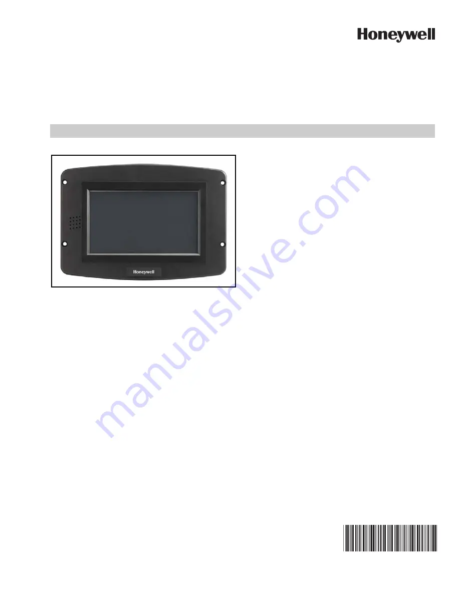
S7999D1048 Combustion System 

Operator Interface Display

APPLICATION

The S7999D Combustion System Operator Interface (OI) 

reduces burner/boiler setup time by allowing the user to create 

a fuel/air modulation curve (profile) for ControLinks

 (Fuel/

Air Ratio Control) that allows for safe and efficient operation at 

all points along the modulation curve. The OI uses a wizard 

like process to assist the user through the commissioning 

process. The S7999D can be used on systems with one or 

two fuels and on systems with or without flue gas re-

circulation (FGR). The S7999D has two RS485 com ports that 

can be configured to provide:

• Fuel/Air Ratio Control commissioning and monitoring

• One or more boiler/burner systems monitoring (up to 99 

burner/burner systems). Each burner control, Fuel/Air 

Ratio Control, and Expanded Annunciator present on each 

burner system can be viewed individually to determine its 

status.

• Local display to a System Monitor

• System Monitor to one or more Local displays

• Gateway for ModBus Master (BAS)

Universal Digital Controllers (UDC 2500/3200/3500 with 

modbus) can be used for several burner/boiler applications, 

and the S7999D can control the UDCs during their operation. 

Applications supported include:

• Stack temperature

• Water/steam PID load control

• Steam/fuel flow monitoring

• Thermal shock

• Feed pump level control

The S7999D is a multiple language OI; English and Spanish 

selectable.

The S7999D can be flush mount or behind mounted into a 

panel cutout.

Wiring connections to the S7999D are through a removable 

8-pin wiring connector.

The S7999D also has a USB port that can be used for:

• Transfer screenshot images

• Transfer Trend Analysis Reports

• To upload:

(1) System OI application software revisions (when 

provided by Honeywell)

(2) Home page background image

(3) Home page logo

(4) Screen saver image

This document provides installation and initial setup 

instructions. Other applicable publications are:

• 66-1200 Combustion System Operator Interface 

Installation Instructions

Documents can be viewed or downloaded at: 

http://customer.honeywell.com 

Contents

Specifications .................................................................... 2

Safety Features ................................................................. 3

Installing the Hardware  ..................................................... 4

Networking Options  .......................................................... 5

Getting started  .................................................................. 11

Starting the S7999 Display  ............................................... 14

Setting up the S7999D display  ......................................... 15

Fuel Air Ratio Control Commissioning .............................. 24

Monitoring.......................................................................... 38

Set Hysteresis .................................................................. 42

UDC Controllers ............................................................... 44

Offline Profile Curve Builder ............................................. 48

Renaming the Expanded Annunciator Terminals ............. 52

Troubleshooting ................................................................ 53

UDC Controller Application .............................................. 58

Summary of Contents for S7999D1048

Page 1: ...r applications and the S7999D can control the UDCs during their operation Applications supported include Stack temperature Water steam PID load control Steam fuel flow monitoring Thermal shock Feed pump level control The S7999D is a multiple language OI English and Spanish selectable The S7999D can be flush mount or behind mounted into a panel cutout Wiring connections to the S7999D are through a ...

Page 2: ...ff line profile curve building Allows programmable expanded annunciator terminal naming Allows burner system naming Allows ControLinks R7999 EEPROM backup and restore Real time data trending analysis and transferring saved trend data to Excel spreadsheet 7 800 x 480 24 bit high resolution color LCD touch screen for clarity Audio output with integral speaker for sound output Adjustable backlight co...

Page 3: ...rporates many features that are designed to guide you safely through the commissioning process Safety however is your responsibility Read all documentation carefully and respond appropriately to all error messages Be aware that as you command the R7999 to open and close actuators the R7999 is designed to prevent you from opening or closing them too rapidly When any of the system actuators are belo...

Page 4: ...8 Ensure the 8 pin connector plug is aligned with the header pins when inserting the 8 pin connector plug back onto the Display Secure firmly Installing the ControLinks and Burner Control Hardware Use the following ControLinks instructions to install the system hardware See Fig 3 for wiring block diagram 65 0238 R7999 ControLinks Control Controller 65 0239 ML7999 ControLinks Control Actuator 65 02...

Page 5: ... Product Data Sheet The R7999 can remain connected to to this COM port following commissioning The Modbus network on the COM port setup for One or more boiler systems ensure the port baud rate matches the ModBus baud rate and the port Modbus addressing range covers the range of addresses of the Modbus devices on the network consists of wiring the S7810M devices together as slaves to the S7999D An ...

Page 6: ...NTROLINKS CONTROLLER R7999 A B C A B C A B C COM POWER S7999D OI DISPLAY 3 1 S7810M MODBUS MODULE C A B 6 7 8 2 C TERMINALS ARE CONNECTED INTERNALLY TO 24 VAC COM 3 SEE 65 0249 FOR MULTIPLE S7810M NETWORK CONNECTIONS 4 MODBUS BAUD RATE MUST BE SET FOR EITHER 9600 BAUD OR 19200 BAUD 5 SEE 65 0238 FOR R7999 WIRING 6 120 Ω 1 4 WATT RESISTOR BETWEEN TERMINALS A AND B OF THE MODBUS AT THE FARTHEST S781...

Page 7: ...twork Wiring for this configuration is shown in Fig 5 S7810M MODBUS RM78xx BURNER CONTROL S7830 EXPANDED ANNUNCIATOR R7999 FUEL AIR RATIO CONTROL S7830 EXPANDED ANNUNCIATOR RM78xx BURNER CONTROL UDC2500 THERMAL SHOCK S7810M MODBUS S7999D SYSTEM DISPLAY CONTROLBUS M33555 COM 1 or COM 2 MASTER SLAVE S7810M MODBUS UP TO 99 BURNER BOILER SYSTEMS AND UDC CONTROLLERS CONTROLBUS SLAVE SLAVE UDC2500 PID L...

Page 8: ...e Fig 8 In the System configuration Modbus addresses of the nodes are learned by the System S7999D so manual assignment isn t necessary Be sure not to duplicate Modbus addresses in the nodes UP TO A TOTAL OF 99 S7810M AND UDC CONTROLLERS CAN BE CONNECTED TO THE S7999D SEE 65 0249 AND UDC MANUALS FOR WIRING M33556 CONTROLINKS CONTROLLER R7999 A B C A B C A B C COM POWER S7999D OI DISPLAY 3 1 C TERM...

Page 9: ...ork wiring S7810M MODBUS RM78xx BURNER CONTROL S7830 EXPANDED ANNUNCIATOR R7999 FUEL AIR RATIO CONTROL UDC2500 THERMAL SHOCK S7999D SYSTEM DISPLAY COM 1 OR COM 2 M33562B S7999D SYSTEM DISPLAY COM 1 OR COM 2 SYSTEM S7999D LOCAL S7999D SYSTEM MODBUS COM 1 OR COM 2 MASTER MASTER SLAVE SLAVE LOCAL MODBUS CONTROLBUS SLAVE UDC2500 STACK TEMPERATURE UDC2500 FEED PUMP LEVEL CONTROL SLAVE UDC2500 PID LOAD ...

Page 10: ... expected to be used after a new Local burner boiler system is attached to the System Modbus network If the quick search isn t done a slower automatic search eventually finds new Local burner boiler systems R7999 FUEL AIR RATIO CONTROL S7830 EXPANDED ANNUNCIATOR RM78xx BURNER CONTROL S7810M MODBUS S7999D SYSTEM DISPLAY S7999D SYSTEM DISPLAY CONTROLBUS COM 1 OR COM 2 M33564C MASTER SLAVE SYSTEM MOD...

Page 11: ...ABLE COM PORT CAN BE CONNECTED TO EITHER A FUEL AIR RATIO CONTROL SYSTEM COMMISSION OR ONE S7810M MODBUS MODULE M33565B A B C A B C COM POWER 3 C TERMINALS ARE CONNECTED INTERNALLY TO 24 VAC COM 3 4 MAKE SURE 24 VAC POWER SUPPLY TO EACH S7999D ARE CONNECTED IN PHASE OBSERVE TRANSFORMER PRIMARY AND SECONDARY WINDING POLARITIES EITHER COM PORT CAN BE USED ENSURE THE BAUD RATE FOR EACH COM PORT MATCH...

Page 12: ... rate must be set for 4800 and COM 2 is configured for one or more burner burner systems monitoring The Baud rate must match the selected Baud rate of the S7810M ModBus Module For network wiring and setup of the R7999 RM7800 S7810M S7830 and UDC2500 3200 3500 with the S7999D refer to 65 0231 Table 1 8 pin Connector Terminals Pin Function 1 COM1 A 2 COM1 B 3 COM1 C 4 COM2 A 5 COM2 B 6 COM2 C 7 24 V...

Page 13: ...ers on 24V COM1 and COM2 wires See Fig 12 and 13 Fig 12 Install clamp filters on 24V COM1 and COM 2 wires Fig 13 Clamp filter in place Battery 1 Remove battery compartment cover on back of the dis play Fig 14 Battery compartment 2 Install CR2032 coin battery included in 50063482 001 Bag Assembly Be sure to follow polarity markings on the display Fig 15 Install CR2032 coin battery 3 Replace battery...

Page 14: ...Setup and Diagnostics Touch the setup button to access the display settings General setup Com Port setup Screen Saver Language selection Home Page Title Date Time Display Diagnostics Com port status Screen calibrations Audio Video tests Display reset Screen Snapshot view snapshots transfer snapshots to USB and other tools Curve Builder Boiler Key Varibles Password setting Control Setup Synchronize...

Page 15: ...and touch OK 5 When the Sound audio alarm for fault box is checked the internal speaker of the S7999D will be activated and a 2 tone alarm will sound whenever a fault occurs in one of the controllers connected to the S7999D Use the vol ume slider bar to adjust the volume level Also an alarm bell icon will be displayed in the lower left hand corner of the screen See Fig 22 Touching the alarm bell i...

Page 16: ...stem Monitor dis play must be the same Touch the port baud rate box to set the baud rate The other Com port can be configured for Fuel Air Ratio control only Commission or One or more boiler systems NOTE If the Com port is configured for One or more boiler systems the local display is limited to only one S7810M Modbus module connected to the Com port System Monitor to one or more Local displays wh...

Page 17: ...he Bitmap type for the customized screen saver image Fig 26 Screen saver tab 10 Language The S7999D provides 2 language options English and Spanish To change the language type select the Language type and then select the desired language and touch the Set Language button Note changing the language requires a display reboot to take effect Fig 27 Language tab 11 Title This option provides the means ...

Page 18: ...t format If the boxes are unchecked then the title will be in standard font format The title font size can be varied from 10F to 24F Touch the size bar and select the desired font size Be sure to touch the OK button for the new font size to take effect The Home Page title can be displayed in various colors Touch the color bar and select the desired color for the Home Page title Be sure to touch th...

Page 19: ...Set Password dialog The Login screen is displayed along with a keyboard to enter the existing password A successful login will display a screen that will allow the user to enter a new password Minimum password string length is one character no spaces allowed Touching the OK button on the keyboard stores the new password in the S7999D display NOTE THIS PASSWORD IS NOT THE PASSWORD THAT IS USED TO C...

Page 20: ... Resume button is touched the data logging is resumed Touching the gray Clear button resets the counters to zero At the bottom of the screen are buttons for screen calibration audio test video test screen snapshot and display reset 1 Calibrate Screen This function allows the user to calibrate the screen to insure the accuracy of touch target to the image on the dis play Touching Calibrate Screen b...

Page 21: ... Modbus Modules are being used that each Modbus Module has a unique Modbus addess 1 99 Also ensure the Modbus address range of the Com port configured for one or more boiler systems is set high enough for all S7810M Modbus modules on the network Finally ensure the baud rate of the Com Port configured for one or more boiler systems and baud rate of each of the S7810M Modbus modules on the network a...

Page 22: ...ion button provides an advanced troubleshooting function that allows the user to read and write to individual Modbus registers The user can read and write any Modbus register in the S7810M Modbus Module or UDC controller The user can enter the Modbus address as either a decimal or hexdecimal value When writing a regis ter value the user can also enter the value in either decimal or hexadecimal uni...

Page 23: ...e 19 for details Table 3 on page 24 lists the possible selections the user can choose for display A different variable can be displayed for each burner boiler system Fig 43 S7999D Home Page with Multiple Systems A fault in one of the burner boiler systems will cause the Fault Dialog box to pop up on the Home Page The Fault Dialog box will indicate which Boiler system has a fault and a fault messag...

Page 24: ...oning Overview The following table provides a step by step overview of how a system is commissioned The Notes column in the table provide references to detailed information when completing the more complex operations Table 3 S7999D Home Page Status Variables Burner boiler system component Status variable Burner Control Sequence state Burner Control Fault code Burner Control Flame Signal Strength R...

Page 25: ...t 7 c Press Lock button 7 d Select the Next button 8 a Press Auto Seek on Maximum Closed Endpoint screen 8 b If necessary press Open or Close to adjust the actuator position to Closed endpoint 8 c Press Lock button 8 d Select the Next button 9 Repeat steps 4 b through 8 d to set the configuration of the other actuators in your system 10 If any System Configuration parameters need to be set select ...

Page 26: ...ent With controller release 1 4 or greater the FGR actuator may have negative slopes maximally negative slope of 1 to 5 anywhere within the modulation band 12 i Press Point button Or press Maximum Modulation With Rev 1 4 controllers or greater the user may alternatively place a maximum modulation point in place of an intermediate as long as a span of at least 17 degrees exists between the minimum ...

Page 27: ...hange 12 l Press Max button An M will be displayed on the profile and a line will connect it to the previous intermediate points The R7999 requires re verification of any verified curve segments after setting the maximum modulation point 12 m Press Prev Point Next Point until the cursor reaches the next lower point on the profile Alternatively the user may add intermediate points as the effective ...

Page 28: ...een is used to Identify the configuration of the system you want to commission for example dual fuel system with a FGR or a single fuel system etc Begin configuration of the actuators Allow the user to set System Parameters Load a curve from the S7999D flash Begin configuration of the modulation curve This screen Fig 49 selects the type Base Configuration of ControLinks Control System to be config...

Page 29: ...uators one air actuator and an FGR actuator 2 Select and configure all actuators within the base configuration b Air Fuel1 Fuel 2 FGR 1 Press a button to configure the actuator If you selected Single Fuel or Single Fuel with FGR in the Base Configuration the Fuel 2 button is not displayed If you selected Single Fuel or Dual Fuel in the Base Configuration the FGR button is not displayed When you pr...

Page 30: ...Commission Configuration screen select the actuator button that needs changing NOTE Buttons are disabled when system is fully commissioned and LCO is on 2 Closed Travel Direction and Actuator Type screen is dis played If no changes are needed select the Next button 3 Serial Number screen is displayed If correct serial number is displayed select the OK button You will be asked if you want to reset ...

Page 31: ...lation position on the graph An M is displayed on the graph to indicate the maximum modulation point Only one maximum modulation point is allowed per curve d Min Press to save the minimum modulation position on the graph An m is displayed in the graph to indicate the minimum modulation point Only one minimum modulation point is allowed per curve e Purge Press to save the air purge position on the ...

Page 32: ...nue curve configuration The following screens depict the options possible to create or change the profile curve for the currently selected fuel The operation of this screen is explained in the Commission Curve screen defined earlier Curve commissioning can only occur after all actuators have been completely configured and locked The Next button on the Commission Configuration screen is not enabled...

Page 33: ...the default values will be used See Default System Parameters for the default value setting for each parameter NOTE The selection of Xma auxiliary mA operation system parameters result in a common attribute between the operation of both fuel selections For example selecting low fire hold will apply to both fuels a Home Press to go to Home page b Back Press to return to the previous screen c Next P...

Page 34: ...ential This field lets you set the differential temperature at which the system will revert to a hold condition The threshold must be set lower than the threshold but greater than the minimum Remember to press the Set button before moving to a different page When the Next button is selected the following figure displays Fig 66 Miscellaneous Commissioning Parameters Controller timing Postpurge Time...

Page 35: ...sioning options are available by selecting the Advanced Options button on the Commissioning Configuration page Fig 69 Fig 69 Advanced Options Factory Default To reset the Fuel Air Ratio Control to factory default select the Factory Default button A confirmation pop up box displays Fig 70 before the reset occurs The user selects the Yes button to continue with the reset This feature is only enabled...

Page 36: ...nto the same R7999 or a replacement EEPROM images for only one R7999 can be saved in the S7999D When no EEPROM images are stored in the S7999D the following figure displays Fig 71 Internal EEPROM contains hysteresis control accuracy and other factory settings External EEPROM contains actuator settings curve data and other settings made by the user during commissioning of the R7999 Fig 71 EEPROM Ma...

Page 37: ...o continue with the download the user is asked to enter an image name to associate with the EEPROM data After the name is entered the OK button is selected To abort the download the Cancel button is selected The download takes less than a minute to execute The user should wait until the download is complete before touching the screen The user can choose to upload the internal EEPROM only the exter...

Page 38: ...ched to the burner system are represented by icon buttons on the Home page To obtain status information about each device the user selects the button that corresponds to the device A new page displays with status information exclusively about that device If any device is currently in a fault condition the device icon is displayed with a red color Also if audio alarm is enabled for fault conditions...

Page 39: ... icon displayed in the lower left corner of the Home page Fig 77 Burner Control Status Lockout The Diagnostic Info button displays the terminal and jumper states of the burner control Fig 78 Fig 78 Burner Control Diagnostic Information The Remote Reset button allows the user to remotely reset the burner control Fig 81 Extreme care should be exercised before proceeding with the reset Disabled for S...

Page 40: ...atio Control R7999 Monitoring the ControLinks Fuel Air Ratio Control system is performed by clicking on the Fuel Air Control icon located on the Home page to display the current configuration status actuator positions and terminal states 1 Fuel Displays the current position of the fuel actuator 2 Air Displays the current position of the air actuator 3 FGR Displays the current position of the FGR a...

Page 41: ...ion Commission configuration selections and diagnostic information about the Fuel Air Ratio Control can be viewed by selecting the View Configuration button on the Fuel Air Ratio Control page A configuration page like the one in Fig 88 displays to show this information Fig 88 Fuel Air Ratio Control Configuration Running Modulation Time is an accumulative time of how long the Fuel Air Ratio Control...

Page 42: ...9 reacts to a firing rate change in the opposite direction The R7999 only reacts to a firing rate change in the opposite direction when it has increased decreased more than the user selected hysteresis value However the R7999 always follows the firing rate signal as it changes in the same direction For example When a hysteresis value of 0 5 mA has been selected and the firing rate drops from 12 mA...

Page 43: ... a S7999D Com port that has been configured for Fuel Air Ratio only Commission the State status indicates whether the actuator has been configured key stop type and close direction has been set or not by displaying CONFIGURED for its state If the actuator has been configured and also has its endpoints locked the state displays a LOCKED status Actuator fault history can be viewed by selecting the S...

Page 44: ...of the programmed curve but many applications may not require this type of accuracy Increasing the control accuracy value may reduce the amount of actuator dither hunting and premature wearout due to a noisy environment or a potentiometer When the Control Accuracy button is selected a new page Fig 100 is displayed Pressing the Set Accuracy button causes the Fuel Air Control to reset and store the ...

Page 45: ...ssing the Key button changes the color to yellow indicating that this status is now a key variable Pressing the Key button again deactivates it as a key variable Only one Key button can be selected at a time because only one key variable status can be displayed on the Home page for each UDC controller If the UDC controller can have its setpoint adjusted by the S7999D and an alarm is configured the...

Page 46: ...urrent stack temperature is obtained from the UDC controller and displayed in text value and in a bar graph on the page Upper and lower limits of the stack temperature range are displayed on the page next to the temperature bar graph Fig 106 Stack Temperature Controller If a High Temperature alarm is configured in the UDC controller the alarm is displayed on the page along with the current alarm s...

Page 47: ...e UDC controller output is also permitted by selecting the yellow Auto Output button Adjustment is raised or lowered in 1 0 16 mA increments The S7999D System password same as Setpoint Adjustment is required before manual control is permitted After successful login the Up Arrow and Down Arrow buttons can be used to change the alarm setpoints PID modulation output is obtained from UDC controller an...

Page 48: ...rrow and Down Arrow buttons after successfully logging in with the S7999D System password Control of the mixing valve pump can be manually adjusted by selecting the yellow Auto Output button The Up Arrow and Down Arrow buttons are used to adjust the modulation outputs override in 1 0 16 mA increments Offline Profile Curve Builder The Offline Profile Curve Builder is used to create a curve without ...

Page 49: ...nt select the point in the list box and the right side of the screen updates with the settings of that point Change any of these settings and select the Save Point button to accept the changes or select the Delete Point button to remove the point from the profile curve the list box on the left side of the screen updates itself with the new settings NOTE To create a profile curve with no FGR enter ...

Page 50: ...age Fig 118 Edit Profile Curve Fig 119 Edit Air Percentage To insert a new point in the curve Select a point in the point list above or below the new point values you wish to insert Edit the point type and actuator open values Select the Add Point button As each point is added to the curve the new point displays in the point list on the left The point list may be reordered to keep it in Air Open o...

Page 51: ... you want to assign the UDC con troller to 2 Select the controller address button to enter Modbus address of the UDC controller or select one of the UDC controllers in the Not Attached list 3 Press the Add Controller button to assign the UDC con troller 4 If the UDC controller is already assigned to another burner boiler system a warning dialog box asks you to confirm the change in assignment from...

Page 52: ... similar to Fig 124 displays Fig 124 Expanded Annunciator Setup The current terminal name settings are listed on the left side of the screen with a scroll bar to move up and down this list The user chooses the terminal to rename by selecting it in this list When the terminal is selected the current setting is displayed on the top of the screen in the Description text box The user touches the Chang...

Page 53: ...OM port that has been configured for One or more boiler systems Check that RS 485 shield is grounded to Earth ground Insert 120 1 4 watt resistor between terminals A and B on farthest S7810M or UDC controller Check for duplicate Modbus addresses in S7810M and UDC controller devices Verify that Modbus baud rates in all S7810M UDC controller devices and the S7999D display match Local S7999Ds Don t D...

Page 54: ...ed Point Under unique actuator loading conditions it may be difficult to land on an existing programmed point This can occur while using the Move Along the Curve command it can also occur when you are completing the curve verification process on extremely flat or steep line segments as you reach the end of the curve If you are experiencing problems back up from the problem point at least 5 degrees...

Page 55: ...metera 43 Feedback potentiometer Interface circuit fault Fuel 2 Verify correct wiring of Potentiometera 44 Feedback potentiometer Interface circuit fault FGR Verify correct wiring of Potentiometera 45 Feedback potentiometer wiper resistance problem Air Check for loose potentiometer wiringa c 46 Feedback potentiometer wiper resistance problem Fuel 1 Check for loose potentiometer wiringa c 47 Feedba...

Page 56: ...uator LED to verify that the actuator that is being brought online A fast flash in the actuator equates to off line state while a 1 second flash equates to an online state 73 Verifies that the Fuel 2 actuator accepted the off line on line move counterclockwise and move clockwise commands Furthermore all potentiometer tests must successfully passed to bring an actuator online Check wiring of actuat...

Page 57: ...The input must be within 3 0 mA to 21 0 mA The voltage at this terminal must be within 0 7 to 5 0 Vdc respectively Conditional Alarm Alarm output is energized controller continues to run e 92 The manual potentiometer rate input is higher than an allowable range i e Out of Range High The actuators move to the maximum modulation point with alarm on control will remain operable yet when MANUAL MODE i...

Page 58: ... application are provided Abbreviation Description Meaning when ON LCO Limit Control Output Limits are satisfied and demand exits The R7999 is operational and able to move all actuators HFP High Fire Proved The R7999 has moved the actuators to the Purge position LFP Low Fire Proved The R7999 has moved the actuators to the Lightoff position Fuel 1 Fuel Select Channel 1 Fuel 1 is selected Fuel 2 Fue...

Page 59: ... 250 OHM RESISTOR STEAM PRESSURE SENSOR STD 904 SERIES UDC CONTROLLER Digital Inputs None Digital Outputs On Off relay Optional Modulation Alarm1 ON when at or below Modulation setpoint OFF when above Modulation setpoint Optional Low Fire Hold Alarm2 ON when at or below Low Fire Hold setpoint OFF when above Low Fire Hold setpoint Analog Inputs Steam pressure sensor 0 750 psi 4 20mA Analog Outputs ...

Page 60: ...EVERSE REVERSE REVERSE REVERSE HYST 0 0 0 0 0 0 0 0 0 0 0 0 0 0 0 0 Options AUXOUT NONE NONE NONE NONE NONE NONE NONE NONE DIGIN1 NONE ToAout NONE ToAout NONE ToAout NONE ToAout DIGIN2 NONE NONE NONE NONE NONE NONE NONE NONE Communications ComADR 30 30 30 30 30 30 30 30 ComSTA MODB MODB MODB MODB MODB MODB MODB MODB BAUD 19 2K 19 2K 19 2K 19 2K 19 2K 19 2K 19 2K 19 2K TX_DLY 1 1 1 1 1 1 1 1 WS FLT...

Page 61: ... R D SHIELD 26 27 25 21 19 17 18 16 5 9 8 6 L2 L1 G C A B L1 L2 RTD SENSOR 100 OHM UDC CONTROLLER Digital Inputs None Digital Outputs On Off relay Optional Modulation Alarm1 ON when at or below Modulation setpoint OFF when above Modulation setpoint Optional Low Fire Hold Alarm2 ON when at or below Low Fire Hold setpoint OFF when above Low Fire Hold setpoint Analog Inputs Vessel water sensor temper...

Page 62: ...K NONE NONE NONE NONE PWR UP ALSP ALSP ALSP ALSP SP Hi 300 300 500 500 SP Lo 0 0 0 0 ACTION REV REV REV REV Options AUXOUT DIS DIS DIS DIS DIGIN1 NONE NONE NONE NONE DIGIN2 NONE NONE NONE NONE Communications ComADR 20 20 20 20 ComSTA MODB MODB MODB MODB BAUD 19 2K 19 2K 19 2K 19 2K TX_DLY 1 1 1 1 WS FLT FP B FP B FP B FP B SDENAB DIS DIS DIS DIS UNITS ENG ENG ENG ENG Alarms A1S1TY PROC PROC PROC P...

Page 63: ...STACK TEMP L1 D R D SHIELD J THERMOCOUPLE 26 27 25 17 18 16 6 4 5 9 8 7 L2 L1 G C A B L1 L2 UDC CONTROLLER Digital Inputs None Digital Outputs High Temperature Alarm ON when at or above alarm setpoint OFF when below alarm setpoint Analog Inputs Stack temperature sensor 0 500 F Analog Outputs None Application File stack01 nge stack02 nge Description 0 500 F High Stack Temperature 0 500 F High Stack...

Page 64: ...ION REV REV HYST 0 0 0 0 Options AUXOUT DIS DIS DIGIN1 NONE NONE DIGIN2 NONE NONE Communications ComADR 10 10 ComSTA MODB MODB BAUD 19 2K 19 2K TX_DLY 1 1 WS FLT FP B FP B SDENAB DIS DIS UNITS ENG ENG Alarms A1S1TY PROC PROC A1S1VA 400 400 A1S1HL HIGH HIGH A1S2TY NONE NONE A2S1TY NONE NONE A2S1VA 50 A2S1HL HIGH A2S2TY NONE NONE ALHYST 0 1 0 1 ALARM1 NO L NO L BLOCK DIS DIS DIA AL DIS DIS Display D...

Page 65: ...ALARM LOW INLET TEMP L1 D R D SHIELD 26 27 25 21 19 17 18 16 9 8 7 L2 L1 G C A B L1 L2 Digital Inputs None Digital Outputs Optimal Temperature Alarm ON when below alarm setpoint OFF when at or above alarm setpoint Analog Inputs Water supply sensor temperature 0 300 F 4 20mA Analog Outputs Proportional modulation 4 20mA to control actuator for mixing valve Modulation based on optimal temperature se...

Page 66: ... installer IN1 LO 300 Input 2 IN2TYP DIS Control LSP S 1 ONLY SP TRK NONE PWR UP ALSP SP Hi 300 SP Lo 0 ACTION REV HYST Options AUXOUT DIS DIGIN1 NONE DIGIN2 NONE Communications ComADR 70 ComSTA MODB BAUD 19 2K TX_DLY 1 WS FLT FP B SDENAB DIS UNITS ENG Alarms A1S1TY PROC A1S1VA 150 A1S1HL LOW A1S2TY NONE A2S1TY NONE A2S1VA NONE A2S1HL NONE A2S2TY NONE ALHYST 0 0 ALARM1 NONE BLOCK DIS DIA AL DIS Di...

Page 67: ...our and or Gas flow sensor 10k 35k ft3 hour or Fuel oil flow sensor 60 260 gal hour 4 20mA Analog Outputs None Application File flow01 nge flow02 nge flow03 nge flow04 nge flow05 nge flow06 nge flow07 nge flow08 nge flow09 nge flow10 nge Description Steam Only Steam Gas Steam Fuel Oil Gas Only Fuel Oil Only TOTALIZATI ON Steam TOTALIZATI ON Steam Gas TOTALIZATI ON Steam Fuel Oil TOTALIZATI ON Gas ...

Page 68: ...NONE NONE NONE DIGIN2 NONE NONE NONE NONE NONE NONE NONE NONE NONE NONE Communications ComADR 50 50 60 50 60 50 50 60 50 60 ComSTA MODB MODB MODB MODB MODB MODB MODB MODB MODB MODB BAUD 19 2K 19 2K 19 2K 19 2K 19 2K 19 2K 19 2K 19 2K 19 2K 19 2K TX_DLY 1 1 1 1 1 1 1 1 1 1 WS FLT FP B FP B FP B FP B FP B FP B FP B FP B FP B FP B SDENAB DIS DIS DIS DIS DIS DIS DIS DIS DIS DIS UNITS ENG ENG ENG ENG E...

Page 69: ... Inputs Level Transmitter 4 20 mA Analog Outputs None Application File pump01 nge Range 0 100 Controller Model DC2500 EB 200R 200 00000 00 0 Algorithm CTRALG ONOFF TIMER DIS Output OUTALG RLY Input 1 IN1TYP 4 20 IN1 HI 100 IN1 LO 0 Input 2 IN2TYP DIS Control LSP S 1 ONLY SP TRK NONE PWR UP ALSP SP Hi 100 SP Lo 0 ACTION REV HYST 0 Options AUXOUT DIS DIGIN1 NONE DIGIN2 NONE Communications ComADR 40 ...

Page 70: ...S7999D1048 COMBUSTION SYSTEM OPERATOR INTERFACE DISPLAY 65 0321 01 70 ...

Page 71: ...65 0321 01 71 Fig 129 S7999D front mount cutout template M33531 4X CLEARANCE HOLE FOR 6 SCREWS 8 203 8 15 16 227 15 32 12 5 1 2 140 3 1 2 89 1 1 2 38 ...

Page 72: ...S7999D1048 COMBUSTION SYSTEM OPERATOR INTERFACE DISPLAY 65 0321 01 72 ...

Page 73: ...65 0321 01 73 Fig 130 S7999D rear mount cutout template 7 1 8 181 8 15 16 227 4X CLEARANCE HOLE FOR 6 SCREWS 29 32 23 4 41 64 118 2X 3 1 2 89 2X 1 5 64 27 M33532 ...

Page 74: ...S7999D1048 COMBUSTION SYSTEM OPERATOR INTERFACE DISPLAY 65 0321 01 74 ...

Page 75: ...S7999D1048 COMBUSTION SYSTEM OPERATOR INTERFACE DISPLAY 75 65 0321 01 ...

Page 76: ...CE DISPLAY Automation and Control Solutions Honeywell International Inc 1985 Douglas Drive North Golden Valley MN 55422 customer honeywell com U S Registered Trademark 2012 Honeywell International Inc 65 0321 01 M S 08 12 Printed in United States ...

Reviews: