S7999D1048 COMBUSTION SYSTEM OPERATOR INTERFACE DISPLAY
45
65-0321—01
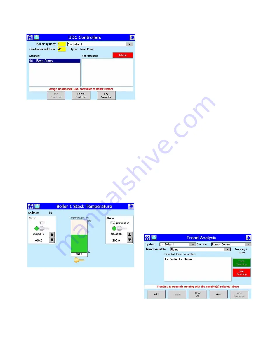
Fig. 102. UDC Controller Setup.
The UDC Controller Setup page can be used to view which
UDC controllers have been assigned, and to manually assign
any future UDC controllers expected to be installed. The
“Refresh” button also provides a quick search to locate any
new UDC controllers that haven’t been detected yet. For more
setup options for UDC controllers, see “Controllers” on
UDC Controller Status
The Home page contains button icons representing the
different UDC controllers (see Fig. 42) in the burner/boiler
system. Selecting one of these buttons displays a status page
similar to the following figure (Fig. 103) providing status and
control options for the selected controller.
The name of the burner/boiler system may optionally be
displayed in the title at the top of the page. The type of the
UDC controller will follow burner/boiler system name..
Fig. 103. Stack Temperature Controller.
The current input reading of the UDC controller is displayed in
the center of the page along with a bar graph showing the
range of the input sensor and the position of the reading in that
range. On each side of the input may be zero, one, or two
alarm indicators, depending on application type and UDC
configuration, to show whether any alarms exist (LED flashes
red) or not (LED is green). If the alarm is turned off for this
configuration, the alarm text and LED are grayed out. The
alarm setpoints can be adjusted with the Up Arrow and Down
Arrow buttons to increase or decrease the setting. Below each
alarm and input reading are Key buttons that allow the
corresponding status to be selected as a key variable for
display on the Home page. Pressing the Key button changes
the color to yellow, indicating that this status is now a key
variable. Pressing the Key button again deactivates it as a key
variable. Only one Key button can be selected at a time,
because only one key variable status can be displayed on the
Home page for each UDC controller.
If the UDC controller can have its setpoint adjusted by the
S7999D, and an alarm is configured, the user must enter a the
S7999D System password to adjust the setpoint. The
password is entered when the setpoint is adjusted for the first
time on the UDC controller status page. The same S7999D
System password is used for all UDC controllers. When the
user leaves the status page, the password expires, and must
be re-entered to adjust the setpoint. The factory default
password is “password”. The password can be changed on the
Display Setup page.
Trend Analysis
The S7999D provides a Trend Analysis function that allows the
user to do real time trending of various analog values in the
Burner/Boiler system. A 60-second, 60-minute, 24-hour, or 30-
day sample history of the analog reading is kept for each
controller input sensor. The trend analysis is displayed as
sensor value over time with the graph updated at run-time once
every second. The user can switch between sample history
times (seconds, minutes, hours, days) by pressing the button
that shows the measurement currently displayed (seconds,
minutes, hours, days).
From the Home page, select the "Trend Analysis" button. The
Trend Analysis screen will be displayed. See Fig. 104. From
the Trend Analysis screen the user can select the Boiler/Burner
system(s), the controller source(s) and the trend variable(s) to
be trended. The selected variables will be displayed in the
"Selected trend variables" box in the center on the screen.
To start trending, touch the green "Start Trending" button.
To stop trending, touch the red "Stop Trending" button.
Fig. 104. Trend Analysis Page.
Summary of Contents for S7999D1048
Page 70: ...S7999D1048 COMBUSTION SYSTEM OPERATOR INTERFACE DISPLAY 65 0321 01 70 ...
Page 72: ...S7999D1048 COMBUSTION SYSTEM OPERATOR INTERFACE DISPLAY 65 0321 01 72 ...
Page 74: ...S7999D1048 COMBUSTION SYSTEM OPERATOR INTERFACE DISPLAY 65 0321 01 74 ...
Page 75: ...S7999D1048 COMBUSTION SYSTEM OPERATOR INTERFACE DISPLAY 75 65 0321 01 ...


