INFORMATION FOR GENERAL USE
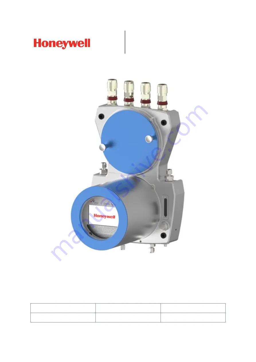
GAS QUALITY ANALYZER GASLAB Q2
DEVICES FROM YOC:
2020
ENSUITE VERSION:
4.7
SW-BASIC SYSTEM:
O3-39-A
DOCUMENT NO.:
73023639
REVISION:
M
RELEASE:
2020-08-11
Page 1: ...INFORMATION FOR GENERAL USE GAS QUALITY ANALYZER GASLAB Q2 DEVICES FROM YOC 2020 ENSUITE VERSION 4 7 SW BASIC SYSTEM O3 39 A DOCUMENT NO 73023639 REVISION M RELEASE 2020 08 11 ...
Page 2: ...act Under no circumstances will the manufacturer accept liability for any direct special or consequential damages We reserve the right to make changes to the device series and documentation in the course of further development They are incorporated without prior notice Contact data Elster GmbH manufacturer Steinern Str 19 21 55252 Mainz Kastel Germany Tel 49 6134 605 0 E mail Customerfirst Honeywe...
Page 3: ...7 Electrical safety information and emergency stop 31 2 8 Data security information 34 2 8 1 General guidelines Software versions and actuality 34 2 8 2 Password guidelines and role based access control 35 2 8 3 Networks and security for data at rest and data in transit 38 2 8 4 Preventing unauthorized external access using a firewall 39 2 8 5 Logging of device events with logbooks 40 2 8 6 Report...
Page 4: ...nd electrical interfaces inputs and outputs 71 5 4 7 Connection to other devices and system parts 73 6 COMMISSIONING AND DECOMMISSIONING 79 6 1 Commissioning preparations and requirements 79 6 1 1 Set password for Administrator admin1 80 6 1 2 Adapting the factory parameterization 80 6 1 3 Opening and closing the hardware parameter guard SSW 80 6 1 4 Additional conditions for fiscal metering 82 6 ...
Page 5: ...4 1 Operating mode Analysis automatic normal operation 137 7 4 2 Operating mode Operational calibration manual 137 7 4 3 Operating mode Verification special mode 139 8 CONFIGURATION AND ANALYSIS SOFTWARE ENSUITE 143 8 1 The PC Software Concept 144 8 1 1 The software blocks AFBs SFBs 144 8 2 Installation Start and Data Connection 145 8 2 1 Installing enSuite 145 8 2 2 Starting enSuite the first ste...
Page 6: ...06 8 5 Remote operation panel functions of enSuite 207 8 5 1 Open and close remote operation panel 207 8 5 2 Enabling the local device functions 208 8 6 Using enSuite functions in device operation 210 8 6 1 Update date and time system time action 210 8 6 2 Displaying and reading analysis results 212 8 6 3 Working with the Modbus AFB 212 8 6 4 Working with archives and logs 213 8 6 5 Live data and ...
Page 7: ...l service work 245 10 5 Device cleaning and documentation of the work 246 11 TECHNICAL DATA AND INFORMATION 248 11 1 Explosion protection data 248 11 2 Reported values and analytical performance 248 11 3 List of suitable gases and calibration gases 249 11 4 Notes on device characteristics and operating conditions 250 11 5 Declaration of conformity 251 12 KEYWORDS AND FIGURES 252 12 1 Keyword index...
Page 8: ...ration use and maintenance In addition to the general specialist knowledge this document enables safe and efficient use of the GasLab Q2 To do so you must have a good command of the documentation language or use another translation of this manual The safety and warning instructions on the device are in English or French Depending on the area of activity trained personnel are assumed to have variou...
Page 9: ...eals with the hardware It contains the explosion relevant information as well as a summary of relevant safety and warning notices In addition to general expertise it enables the Q2 to be handled safely and efficiently The chapters 7 and 8 software are addressed to measurement operator s and explains the basic functions of the measuring instrument and how to operate the Q2 in detail The chapters 9 ...
Page 10: ... signifie un danger de blessures graves et d atteinte à la santé pouvant entraîner la mort si les mesures de précaution appropriées ne sont pas prises Very serious health impairment Prohibited action means that you must not complete the action described unless the specified conditions and requirements are satisfied and you are qualified for this work signifie que vous ne pouvez pas exécuter ce qui...
Page 11: ...used to navigate through various displays In this example the system is switched to a different calculation standard See chapter 7 for more information Liens hyperliens par les hyperliens vous pouvez naviguer vers différents affichages Dans cet exemple le lien renvoie à une norme de calcul différente voir le chapitre 7 pour plus d informations Message and signal identification Alarm Warning Note i...
Page 12: ...exane C7H16 Total heptane C8H18 Total octane CAL Calibration gas inlet CEC Canadian Electrical Code CH Total of all hydrocarbons CH4 Methane cm Length 1 cm 10 mm 0 3937 in 0 3937 CO2 Carbon dioxide CPU Central processing unit CSA Canadian Standards Association independent standards organization CVDD Calorific value determining device d rd Relative density density ratio of fuel and air DBB Double b...
Page 13: ...e i butane iC5H12 Isopentane i pentane ID Identification number enSuite for example gas cylinder number IECEx IECEx SYSTEM International explosion protection Ex rating in or length in inch 1 1 in 1 0 0254 m 25 4 mm IP Internet protocol Protection class IR Infrared ISO International Organization for Standardization K Temperature Kelvin TK 5 9 TF 459 67 TC 273 15 1K 1 C KFM Live Internal coefficient...
Page 14: ...h output which is open when de energized NO contact NPT National Pipe Thread self sealing pipe thread NTP Network Time Protocol Standard for clock synchronization in computers O2 Oxygen PA Equipotential bonding connection PC Personal computer PELV Protective extra low voltage PG Process gas Measuring gas PI Internal pressure internal monitoring ppm Parts per million Pressure g Overpressure g gauge...
Page 15: ...ransmission Control Protocol Internet TH1 Housing temperature TLS Transport Layer Security transmission protocol TM1 TM2 Internal calculations TP Circuit board temperature internal monitoring TSB Temperature of sensor block VDE German Association for Electrical Electronic Information Technologies VPN Virtual Private Network WEEE Waste of Electrical and Electronic Equipment directive of the EU Wi I...
Page 16: ...which enables the user to conduct changes relevant to billing without opening the SSW These changes are monitored and documented in the fiscal section If the SSW is opened data are only included in the general section Base calibration is a factory adjustment of the device using multiple gases before delivery It may be repeated by Honeywell if necessary in adjustment procedures Breathing device The...
Page 17: ... a range of measuring devices based on similar modular hardware and software Their configuration is variable In addition to the GasLab Q2 these include the volume conversion device enCore ZM1 the signaling and monitoring unit enCore MC1 and the flow computer enCore FC1 enSuite The configuration and analysis PC software for current Honeywell Elster devices in the field of flow computer data storage...
Page 18: ...ater vapor Ground loop Grounding the devices may create ground loops since the cable screens create additional connections if they are connected to both sides A ground loop is electric cabling closed to create a loop In the event of low frequency error currents an undesirable voltage drop occurs in the signal path and an interference signal is added to the signal as a result of the impedance of th...
Page 19: ...rmanently connected to the GasLab Q2 and is an integral part of the measurement device This is a mixture of methane and carbon dioxide with officially defined properties and is required for automatic calibration Ordinal number or sequence number is an automatically assigned identification number for archived data This is formed so that the very first archive entry has the number 1 The number is in...
Page 20: ...f the concept to limit user rights Since a change requires the housing to be opened this may only be done by trained personnel with the authorization of the manufacturer SELV SELV safety extra low voltage systems which comply with DIN EN 60079 14 The power supply to generate SELVs must ensure that no short circuit is possible between the primary voltage and the extra low voltage and its connection...
Page 21: ...tem time is the generic term for both synchronizing and adjusting these values Further information is provided in the manual entitled enCore ZM1 MC1 FC1 basic system with SFBs Test gas See Verification gas Time stamp are time details which relate to an event They contain the time in seconds since 1 January 1970 the local time zone and the local time difference additional deviation in minutes The f...
Page 22: ...tant for monitoring the measurement The calculation is continued without falsification If the cause no longer exists it can be accepted on the operation panel and the entry thus removed from the error list WEEE Directive The Waste Electrical and Electronic Equipment Directive dated 14 August 2018 is designed to prevent and reduce waste from electrical and electronic equipment particularly in house...
Page 23: ...ssible other translations M 2020 08 11 Software Hardware statuses included in documentation Update control and data security introduced Remote control panel no longer accessible via http Updates for connection to device parameterization and software configuration This document revision M is also available online in PDF format for the duration of its validity and can be downloaded from our Docuthek...
Page 24: ...ou discover that the measuring equipment or other parts used for measuring are damaged shut down everything disconnect everything from the gas and electricity supplies and secure them to prevent them being used accidentally Si l on constate que l appareil de mesure ou d autres parties intervenant dans la mesure sont endommagés tout doit être mis hors service débranché de l alimentation en gaz et e...
Page 25: ...r exemple au moyen de réductions de haute pression et de dispositifs de sécurité à ce que la pression maximale admissible à l entrée du dispositif dans l installation fluidique située en amont du dispositif ne soit pas dépassée même en cas de défaillance The operator must ensure that no dangers exist or can arise for persons or components for example due to the electrical installation or lightning...
Page 26: ... and with the consent of Honeywell Dans un environnement venteux avec des températures inférieures au point de congélation une protection contre le vent peut être nécessaire Il faut veiller à ce que l appareil ne soit pas exposé à des températures inadmissibles lors de son stockage et de son utilisation par exemple par une armoire climatisée La plage de température 25 C 13 F 248 K à 55 C 131 F 328...
Page 27: ...dition sine qua non The appropriate specialists have the expertise set out in Annex A of EN IEC 60079 14 or have comparable expertise including the following General safety rules Care and use of reasonable safety equipment Electrical safety and explosion protection rules Working on electrical circuits for systems with potentially explosive atmospheres Working with high pressures and aggressive or ...
Page 28: ... ensure there is adequate ventilation and protect yourself from gases which contain aggressive or toxic components Lorsque vous travaillez sur les conduites de gaz assurez vous qu il y a toujours une ventilation adéquate et que vous êtes protégé e contre les gaz aux composants agressifs ou toxiques Do not connect gases which are potentially flammable or explosive without the presence of oxygen for...
Page 29: ...ameter of 8 mm 0 31496 inch and a suitable inlet pressure lengths of around 40m 131ft are possible If you would like to use different diameters and lengths of over 40m 131ft please contact Honeywell The completely separate line must be protected from dirt insects and rain by the system operator and ensure permanent atmospheric ventilation The breather element and or the vent line must not be close...
Page 30: ...elines and connections from dirt DO NOT OPEN THE DEVICE IF IT IS IN A POTENTIALLY EXPLOSIVE ATMOSPHERE or IF THE CONDITIONS DESCRIBED IN ISO IEC 61010 1 ARE NOT COMPLIED WITH N OUVREZ PAS L APPAREIL DANS UNE ATMOSPHÈRE EXPLOSIBLE au DANS DES CONDITIONS NON CONFORMES À ISO CEI 61010 1 All covers and hoods which can be unscrewed to open the housing must be protected against accidental opening by saf...
Page 31: ...uired Le système TBTP ou le système TBTS peut être utilisé Toutes les parties électriquement conductrices boîtier et le cas échéant constructions de montage doivent être incluses dans la mise à la terre ou la compensation de potentiel À cette fin le point de connexion de liaison équipotentielle PA marquée GROUND sur le fond du boîtier de l appareil doit être utilisé dans tous les cas Des connexion...
Page 32: ...K à la température ambiante maximum The device does not have its own off switch It must be operated using an isolating device switch or circuit breaker and current limiting device or a combination of the two to comply with ISO IEC 60079 14 and ISO IEC 61010 1 The isolating device must be able to safely isolate at least twice the operating voltage 48 V DC L appareil n a pas d interrupteur marche ar...
Page 33: ... in Canada ONLY Japanese Ex approval listed cable inlet equipment must be used in Japan Please contact Honneywell for information on permitted fitting types Les dispositifs d entrée de câble doivent atteindre ou excéder la classification IP IP 64 Pour une utilisation aux États Unis les dispositifs d entrée de câble doivent être conformes au NEC Pour une utilisation au Canada les dispositifs d entr...
Page 34: ...version before using the device You should also check from time to time whether the software used is still up to date Check on the website www elster instromet com en software downloads whether your enSuite version is still up to date download the latest version if necessary and install it To do this you will find information on this website and under Installing and starting enSuite in this docume...
Page 35: ...re protection increases with the length of the password The role based authorization concept of the enCore device series is another tool for increasing data security Six different roles with six user profiles help to ensure correct operation with correspondingly restricted access An administrator profile and five super user profiles su1 su5 are always available The device is delivered without pres...
Page 36: ...with the required user profile by the administrator after password creation An example is shown in the table at the end of the section By default users of profiles 1 5 have read only access to the enCore device after login To ensure data consistency only one user can be exclusively logged on to the device at a time and changes can only be made after successful login Apart from password protection ...
Page 37: ...ss of the official measurement seal device Minimum required rights Rights must be adjusted rights at system level Change device system time Reset battery status Change AFB configuration Change legally relevant and operational software Change general system settings Erase fiscal audit trail fiscal archives Change approval file rights at parameter level Right to change all parameters that are protec...
Page 38: ...n the enCore device is put into operation and announced to enSuite during the first MMS connection This certificate is retained until it is changed deleted manualy To increase security we recommend changing this certificate on the enCore device or on the remote operation panel before regular operation and having the device create an up to date certificate with administrator and user passwords set ...
Page 39: ...ports only that are actually used for data exchange with the external network e g by adding these to the white list of the firewall and allow data exchange with trusted participants only Supported data protocols for GQ devices are shown in the following table Protocol Standard port Description MMS 102 Manufacturing Messaging Specification pursuant to ISO standard 9506 allows communication between ...
Page 40: ...nd the following system events are logged here System messages All parameter changes User login and logout Setting counters All entries in the fiscal audit trail The audit trail has a depth of 1000 entries As soon as the logbook is full and another event occurs the oldest entry is overwritten by the latest entry using the FIFO first in first out principle Fiscal audit trail enCore devices which ar...
Page 41: ...ting Honeywell products and services For details on Honeywell security policy visit https www honeywell com product security To report a potential security vulnerability against any Honeywell product please follow the instructions at https www honeywell com product security under the Vulnerability Reporting section To view information on current malware threats please visit https www honeywellproc...
Page 42: ... Disposal of the memory card and device are subject to environmental protection regulations Si la carte SD est retirée de manière incorrecte des dommages matériels supplémentaires sont possibles La mise au rebut des cartes et des appareils à mémoire est soumise à la réglementation sur la protection de l environnement All data of the device is stored on the SD card This card is located on a separat...
Page 43: ...perature range from 25 C 13 F 248 K to 55 C 131 F 328 K From a functional point of view the hard work can be divided into three sections Figure 3 1 Overview Hardware sections The connection section shown in orange in the diagram constitutes the interface to external connections such as the gas supply and electrical cables The instrumentation section shown in yellow in the diagram primarily contain...
Page 44: ...M 73023639 44 GasLab Q2 3 1 Connection section The connection section is sub divided into the following parts Gas connections inputs outputs and breather Electrical connections cable inlet and connection circuit board Figure 3 2 Overview of connection section connection points ...
Page 45: ...he main breathing device is in the middle of the bottom the auxiliary breathing devices are located on the back of the device in the upper part of the housing Further information 5 3 Fluid installation of GasLab Q2 Electrical connections cable inlet and connection circuit board Figure 3 2 shows an example of four cable glands for electrical inputs and outputs on the top of the instrument If requir...
Page 46: ...of the housing on the right hand side The right hand flow meter and the right hand needle valve are used to display and regulate the flow of vent gas from the measurement The side markings of this flow meter show the usual flow rates of approx 30 l h bottom approx 40 l h middle and approx 60 l h top The left hand flow meter shows the gas flow in the bypass This can be used optionally e g for long ...
Page 47: ... of the measured and target values as well as control and settings A screen keyboard is displayed if necessary Various languages are possible In addition the HMI area consists of electronic circuits on circuit boards which are invisible to the operator These share the cylinder of the instrumentation area with the measuremen components and handle the control display and archiving of measurement dat...
Page 48: ... on the country of use and the approvals The type labels will vary in terms of language and the specified standards or regulations However the following information is always contained on the label s Information Manufacturer and manufacturer s address with the address of the production site Device type type designation serial number and year of manufacture MM YYYY Warning to refer to this document...
Page 49: ... the specifications on the respective device apply For EU Approval number DEKRA 15 ATEX0113X IECEx DEK 15 0075X CE mark with auditor number Approval number FM FM17US0040X FM17CA0027X Class I Div 2 Groups ABCD T4 Ex rating II 2G A Ex db IIC T4 Gb for ATEX IECEx and FM Depending on application measuring ranges of the evaluation certificate according to OIML R 140 for calorific value determining devi...
Page 50: ...ws for the direction of gas flow Maximum inlet pressure process gas Maximum inlet pressure Calibration gas Potential equalization connection point PA Figure 3 7 Engraved device Information 3 5 Explanation of explosion protection markings Icons symbols Meaning Designations around these symbols on the nameplate indicate the area of application taking explosion protection into account Notified body d...
Page 51: ...n and prevent transmission to the atmosphere surrounding the enclosure IIC Ex marking of explosion group Explosion group Group I contain equipment for mine workings endangered by firedamp Group II for all other potentially explosive atmospheres The classification is based on the equipment design and the hazardousness of the gases It increases from expl group II A to II C T4 Ex marking of temperatu...
Page 52: ...od uses values which are physically related to the target values and are easier to measure GasLab Q2 therefore analyzes the following gas properties Infrared IR absorption of the CH gas Infrared IR absorption of the CO2 gas Thermal conductivity of the full gas mixture Pressure and gas temperature All the partial measurements are subjected to a correlative evaluation process which is based on the p...
Page 53: ...he device The sensor block consists of parts with gas channels as well as the electronics and sensors An integral pressure regulator reduces the inlet pressure for measurement The measuring system typically operates at a gauge pressure of around 16KPa 2 32psi 160mbar The gas is then supplied to the actual sensor chamber The infrared sensor and the thermal conductivity sensor analyze the gas there ...
Page 54: ...pstream of the process gas inlet The operational calibration gas mixture is generally supplied using a gas cylinder with a pressure reducer near the GasLab Q2 and ensures that the measuring accuracy is maintained The gas in a 10 l 0 01 m3 0 353 cft cylinder will suffice for several years of operation The vent waste gas line should be routed separately see section 5 3 2 Connect the vent gas line fo...
Page 55: ...surement device and any other components and check them for signs of damage and missing or incorrect parts 2 Install the device in its position using the fastening materials provided 5 2 Mechanical installation of GasLab Q2 3 Connect the gas pipelines and the auxiliary and vent lines to the GasLab Q2 and set the gas pressures open the shut off valves and check all lines for leaks 5 3 Fluid install...
Page 56: ...om temperature temperature at the place of use in order to prevent damage caused by the formation of condensation Do not remove transport guards and other safety devices for example for gas connections before the device has been installed at its destination and if dirt can still penetrate it Le retrait des dispositifs de protection de transport et des dispositif de protection par exemple des racco...
Page 57: ...enough to support it The installation site must meet the safety conditions Le site d installation doit répondre aux conditions de sécurité 2 2 Place of use Environmental conditions and installation The sand guard HMI cover should be screwed on in sandy environments Please contact Honeywell for further information La protection contre le sable couvercle de l IHM doit être vissée dans les environnem...
Page 58: ...e Rev M 73023639 58 GasLab Q2 5 2 2 Device dimensions Please note that all dimensions in the following drawing are shown in mm The dimensions with information 1 2 3 depend on the types of fluid and electrical couplings used Figure 5 1 Dimension drawing with optional sand guard ...
Page 59: ...n accordance with the applicable general rules and the specifications in this manual The maximum pressure at the gas inlets of the device must not be exceeded so as to prevent damage and dangerous situations This must be guaranteed on site by external protection which is not part of the GasLab Q2 La pression maximale spécifiée pour les entrées de gaz de l appareil ne doit pas être dépassée afin de...
Page 60: ... integrated bypass Flow rate up to around 300 l h 0 3 m3 h 10 59ft3 h if necessary 4 Outlet from sensor path Typical flow rate 1 059ft3 h 0 03m3 h 30l h Max flow rate 2 118ft3 h 0 06m3 h 60l h h 5 Main breather with NPT connection thread for pipelines as described in section 2 6 If a pipe line is connected it must be separate from all other vent waste gas lines 6 Auxiliary breathers on the reverse...
Page 61: ... at least 1m 3 28ft 3 m 9 84ft recommended If the bypass has a high flow rate it should preferably be equipped with a separate vent waste gas line to prevent return effects Please contact Honeywell in case of deviating exhaust gas conditions If the bypass is not used the outlet must be closed by a gas tight dummy plug The needle valve not gas tight on the left side of the device may also only be o...
Page 62: ...o its lowest setting 2 Check whether the pressure and other parameters are correct and connect the end of the line intended for the device connection to the vent gas properly using a hose 3 Carefully open the shut off valves to create a permitted gas flow above the operating conditions Then flush for around 30 seconds to clean the pipeline system For very long lines you must extend this time accor...
Page 63: ...mes locales en respectant les instructions de ce manuel Refer to Respectez les 10 3 Connecting and replacing gas cylinders Failure to do so may result in significant destruction of the device or the system Le non respect de ces étapes peut entraîner des dommages importants sur l appareil ou l installation Step Action Prepare the calibration gas line connecting the device 1 Connect the end of the l...
Page 64: ...als before any change of the wiring The local national installation guidelines e g EN 60079 14 must be observed for all work The device must be connected to the equipotential bonding or earth at the place of use The explosion protection is lost if the cable glands are installed incorrectly the installation is explosion safety relevant Make sure that the installation is safe and correct The manufac...
Page 65: ...thermal and electrical fuses cannot be reset Please contact Honeywell if this protective device has tripped See also 9 Possible malfunctions and troubleshooting Check the voltage used at the place of use to ensure it is correct and suitable as described in the following data Power supply see also section 2 7 Voltage range 24 V DC Fluctuations including mains fluctuations 15 An external safety devi...
Page 66: ...rature du boîtier de jonction peut monter jusqu à 10 C 18 F 10K au dessus de la température ambiante Les câbles doivent être adaptés à cette augmentation de la température ambiante locale The connection terminals are suitable for conductor cross sections from 0 25 mm 24 AWG to 2 5 mm 14 AWG Signal cables require conductor cross sections of 0 25 mm 24 AWG We recommend signal cables with a conductor...
Page 67: ...norme ISO CEI 61010 1 These conditions temperature 5 C 41 F 278K to 40 C 104 F 313K humidity up to 80 at 31 C 88 F 304K decreasing linearly to 50 at 40 C 104 F 313K generally prevail in residential and office environments If you are in any doubt read the standard or contact Honeywell Before working on the device turn off all gases mark your work on the switched off supply voltage and secure it aga...
Page 68: ... be used with no modifications The torque for the connection must not exceed 3 5Nm 2 582 ftlb If GasLab Q2 is mounted on a metal plate the plate must be properly included in the grounding and the equipotential bonding system Use the appropriate connections or install such connections There is another functional earth point FE in the connection box see Figure 5 4 The device will only operate correc...
Page 69: ...arts Select a suitable type of cable gland depending on the location and requirements contact Honeywell if necessary In order to maintain the specified explosion protection the screw in parts must be must be installed and cast in accordance with the gland manufacturer s specifications Compliance with the IP rating may require the use of sealing rings Openings which are not required must be fitted ...
Page 70: ...s or conduit stop boxes if they are sealed or potted Under FM conditions these must be sealed within 18 45cm For ATEX and IECEx this distance is 1xD from the enclosure as for a normal cable gland Please contact Honeywell if you wish to deviate from the standard equipment If cable glands and dummy plugs are not pre assembled on the device the following applies with regard to installation and replac...
Page 71: ... 4 digital outputs electrically isolated common return cable 1 breaker closed when de energized suitable for general alarms 3 makers circuit operates as a floating contact max 120 mA at 28 8 V DC TB7 4 analog outputs 0 4 20mA electrically isolated common return cable short circuit resistant R max 390 Ω Never remove the plug connection in the center of the connection board next figure Ne retirez ja...
Page 72: ...GASLAB Q2 AFTER DELIVERY AND AT THE PLACE OF USE Information for general use Rev M 73023639 72 GasLab Q2 Figure 5 6 Electrical connection assignment circuit board ...
Page 73: ...achment It is extremely important and mandatory that there are no grounding potential differences between the end points of the shield Benefit EMC compliant connection is also effective against inductive coupling components Drawback Compensating currents ground loop formation which flow through the screens should be prevented where possible and require appropriate action 2 One sided attachment Ben...
Page 74: ...side Q2 EIA TIA 568 B EIA TIA 568 A IEC REA DIN 47 100 1 4 5 blue white blue blue white white blue white blue white brown 2 3 6 white green green white orange red orange turquoise violet green yellow Only core pairs 2 and 3 are required TB3 3 TB3 4 3 1 2 white orange orange white green black grey white orange grey pink TB3 1 TB3 2 4 7 8 white brown brown white brown yellow brown turquoise violet b...
Page 75: ...ystem or connected to GND Pull up pull down resistors should be installed at the cable end near the data evaluation unit to generate the neutral potential A 470 Ω resistor must be connected between RSA and the positive supply voltage of the connected data evaluation unit A further 470 Ω resistor must be connected between RSB and GND For cable lengths over 200 m 656ft additional bus connection resi...
Page 76: ...e maximum supply voltage is approx 9 V For cable type refer to 5 4 2 Cables power supply communication The figure also shows the appropriate terminals in the connection box The wiring in the drawing is only designed to illustrate the screening using an example Figure 5 9 Example connection of digital inputs In addition to the wiring various enSuite settings are required before this interface can b...
Page 77: ...ly open The maximum load per channel is 28 8 V DC 120 mA The maximum pulse rate is 25 Hz Cable type refer to 5 4 2 Cables power supply communication the maximum length is 250m 820ft The figure also shows the appropriate terminals in the connection box The wiring in the drawing is only designed to illustrate the screening using an example Figure 5 10 Example connection of digital outputs In additio...
Page 78: ...upply voltage is around 9 V The maximum load is 390 Ω Cable type refer to 5 4 2 Cables power supply communication the maximum cable length is 500m 1640ft The figure also shows the appropriate terminals in the connection box The wiring in the drawing is only designed to illustrate the screening using an example Figure 5 11 Sample connection of digital outputs In addition to the wiring various enSui...
Page 79: ... 7 GasLab Q2 Displays Operate the Device and 8 Configuration and analysis software enSuite of this document before you continue Refer to the regulations for explosion protection and the safety information particularly for starting up the device in a potentially explosive atmosphere Les exigences relatives à la protection contre les explosions et à la sécurité doivent être respectées en particulier...
Page 80: ... the additional heating system at 0 C 32 F 273K with a switching hysteresis of 2 C 3 6 F 2K This supplementary heater function is only available up to a maximum housing temperature of 13 C 55 F 286K Other parameters are normally left at their factory set values and if necessary supplemented by customer specific requirements To understand these parameters and to change their values if necessary ple...
Page 81: ... 61340 5 1 Proceed with the appropriate care To open the instrumentation section screw in the locking screws see figure Then remove the hood by turning it counterclockwise You will now see the elements in the section in front of you The SSW is a physical connection jumper to the main circuit board Q2BASE next to the battery Figure 6 1 Overview of security switch SSW position The following figures ...
Page 82: ...device that adjusts the settings For final commissioning the calibration switch or security switch SSW must be closed You can attach a seal directly to the SSW jumper to prevent or detect unauthorized access Within the scope of fiscal metering depending on the regulations of your country for the final commissioning the presence of an authorized person calibration officer who carries out officially...
Page 83: ...es the operating range 70 C 158 F 343K a start delay which is also displayed will commence Outputs and inputs of the device are not yet active during this time After the start delay has expired the instrument is flushed with measuring gas and the inputs and outputs are activated The device then automatically switches to standard mode known as Analysis This is displayed on the screen of the instrum...
Page 84: ...e valve spindle is secured with a lock nut which must first be loosened and tightened again after adjustment The needle valve on the right hand side of the device see Figure 4 2 is for regulation only it is not a shut off valve and must never be fully closed La vanne à aiguille située sur le côté droit de l appareil voir fig 4 2 sert uniquement à la régulation il ne s agit pas d un robinet d arrêt...
Page 85: ...set les réglagesde l heure seront perdues si labatterie est vide L appareilnedémarrerapluscorrectement Vousdevrezalorsfaire appel àun service d entretien Honeywell To complete dismantling or disassembly continue the above steps with the following note before If the device contains hazardous media e g toxic gases they must be removed before its dismantling Prevent the release of potentially polluta...
Page 86: ...ndustrial waste Please ask your local Honeywell sales partner how the take back of your equipment is regulated Batteries are subject to hazardous waste treatment and must therefore be removed before disposing of the enCore device If necessary ask your Honeywell sales partner how to treat used batteries in your country Les piles sont soumises à un traitement des déchets dangereux et doivent donc êt...
Page 87: ...s of access to the instrument are possible Access methods 1 via the operation panel local on the device described in this chapter 2 via a PC or laptop with the Configuration and analysis software enSuite described in Chapter 8 For each type of access applies The device has a user management system protected by a password to protect important settings and simplify the parameterization process There...
Page 88: ...s in the error list The device functions perfectly in measuring mode Information on the error list see section 7 3 8 Error List Main display accepting quit error messages A red or yellow status LED indicates that there are pending errors or errors which have not been accepted The LED status will be retained even after a restart and will be redisplayed The status LED shows the error state as follow...
Page 89: ...re used to display the measurements and to control the various operating modes for example analysis process gas measurement calibration and date setting Result influencing official parameters cannot be changed The configuration and analysis software enSuite with its extended functions is designed for this purpose The operation panel features 7 touchscreen boxes for this purpose see red areas in th...
Page 90: ...re 7 1 or if you click in the areas with red borders in the remote operation panel see Figure 7 2 direction arrows will be displayed pointing left and right as well as up and down A confirmation arrow will appear at the bottom of the display These displays are known as superimposition keys If no further taps or clicks are made these keys will disappear again There are only slight display differenc...
Page 91: ... will be active for a further 20 seconds The keys will be displayed again if actions take place during this time If 30 seconds pass without activity the display will return to its initial state Since some displays are too long to be shown completely a small yellow diamond on the right hand edge indicates where you are in the list You can scroll through the list of displayed values using the superi...
Page 92: ... function Dialogs appear for editing values A drop down list can be identified by the triangle on the small grey box next to the value with everything being framed in blue when selected Input boxes show their values in white boxes When a value has been selected it will be displayed with a blue background and there will be a blue border around the box See the following examples Figure 7 6 Drop down...
Page 93: ...r example device monitor press the confirmation arrow box on the device in the center of the bottom line On the remote operation panel click in this area Figure 7 7 Selecting and executing hyperlinks and actions There are two sensitive navigation areas on the bottom edge of the display which may be available and change their appearance depending on context The figure below shows the possible combi...
Page 94: ...ous display for example from the Device monitor to Info Q2 Tap the display or click on 3 Back from any point via Home to the Q2 main display for example from the Device monitor display Tap the display or click on to go to the Home display display Info Q2 is skipped in this example the symbol changes to Tap or click on to go to the Q2 main display Regardless of the current device display you can al...
Page 95: ...rs in every display In non fiscal operation this connection may be open and the symbol is displayed Since the housing must be opened to close the security switch SSW special rules apply see section 6 1 3 Opening and closing the hardware parameter guard SSW You can also have a seal affixed to the switch its selve to verify unauthorized access Please contact Honeywell if necessary If the symbol is s...
Page 96: ...t is active Without user login remote operation panel and with closed security switch SSW no symbols are visible Further information will follow in the course of this manual When accessing the device via remote control the local user sees a lock screen on the device by default unless the remote user changes these settings see section 8 5 Remote operation panel functions of enSuite The lock screen ...
Page 97: ...n made will be discarded Entries and changes can be made either using a drop down list or the displayed keypad Changes using a drop down list are shown in the following example A drop down list can be identified by the small gray box with a triangle next to the value to be changed in this example after month and day The view will change when you click on it in the example the year Figure 7 11 Drop...
Page 98: ...mber pad When this is pressed the special characters will be displayed and can be selected The superimposition keys enable you to select a key button in the box Your selection then has a blue background You can adopt the selected value using In this case the keypad will remain open and you can select and add another value in the box If all the values are already filled in you can close the keypad ...
Page 99: ... various other displays and functions are then presented as well as the details described 7 3 1 Home display overview device language start up error After start up or power up the Home display can be accessed using This is a special display it shows the software structure of the GasLab Q2 Individual software parts and selected other functions which should be easy to access for example changing the...
Page 100: ...e but have not been accepted section 7 3 8 Error List Main display accepting quit error messages 4 The gear wheel symbol opens the System display another node to the displays for the time service user management logbooks and I O functions sections 7 3 9 7 3 10 7 3 11 7 3 12 7 3 13 7 3 14 5 The Q2 sensor values display supplies the current incoming measurements raw values from the transmitters and ...
Page 101: ...native language is shown below the symbol Confirm your selection 2 The language has changed The text beneath the Globe shows the previous language as the new alternative Error display after start up or for system errors A system error may occur in very rare cases If this happens a prohibition sign will be displayed and the device will switch to emergency mode Figure 7 15 Device not ready Examples ...
Page 102: ... settings and software downloads see section 8 4 12 Changing the software configuration Update Downgrade Figure 7 16 Info System display Furthermore the display provides access to the following functions 7 3 3 Info display Serial number and TLS certificate The serial number shows after a klick on it as second display information of the device type and the used CPU The link Certificate enables to v...
Page 103: ...ince the display is too long to be shown completely use the small yellow diamond on the right hand edge or scroll use the up and down arrows on the display Figure 7 18 Display certificatepage one and two example To increase security we recommend that a new TLS certificate always be created if the existing one was made under unknown conditions e g on the transport route or in trial operation ...
Page 104: ...h the action Reboot and create certificate On restart the device generates a new certificate for MMS communicationt 7 3 4 Info display Device monitor The device monitor shows information about the operating hours and battery charge and about the CPU and RAM load Figure 7 19 System info Device monitor display The battery is mainly used when the device is switched off After service or repair work in...
Page 105: ...ast check the topmost line contains the date of the readout for the following information The first column lists the names of the software parts These names are selectable hyperlinks and take you to subordinate displays component displays containing information on the corresponding software part The second column contains the software version number of the components and the third column contains ...
Page 106: ...his case as in the example above NonFiscal is displayed as the abbreviation If the device is operated with an approval file and a closed SSW the appropriate parameters are protected to prevent them being changed If you wish or have to backup parameters with an approval file refer to section 6 1 3 Opening and closing the hardware parameter guard SSW and section 8 4 10 Fiscal parameters and optional...
Page 107: ...all the pixels in the display area are switched on and off alternately This enables you to check whether the screen is working correctly You can end the test using or Figure 7 22 System info Display test display 7 3 7 Info display License info The hyperlink leads to a display with details of licenses copyright and rights Figure 7 23 System info License info display ...
Page 108: ...t have not yet been accepted These alarms and warnings also affect the reaction of the status LED After it has been opened the list is frozen to avoid having to re sort the entries The list is arranged in ascending order by date and time The last event before the display was opened is at the top Time stamps date and time of the start of the error and if applicable the end of the error are shown ab...
Page 109: ...the error on the right if applicable with the relevant message beneath If the list contains more than 2 events you can scroll through it yellow diamond on the right hand edge Action Refresh the error list which was frozen when it was opened will be updated Link to go to the logbook you can go to the Logbook error list See section 7 3 12 System display Logbook The error list is sorted in chronologi...
Page 110: ...propriate entry 3 Select Refresh to update the list which had been frozen upon opening number in brackets number of new messages 4 Start the Accept all action The selected list will be accepted and refreshed according to the parameterized acceptance action 5 Repeat these steps for other display texts from other software parts if necessary After all the entries have been accepted the system will be...
Page 111: ...date and time is saved on a battery buffered clock block The time or system time is therefore available even after the device has been switched off and on again Changing the system time is the generic term for both synchronization and for adjusting the date and time The time service to output and change the device s internal time has up to four standard displays These displays will change dependin...
Page 112: ...authentication the main display branches to the corresponding display to change the system time The hyperlink NTP overview is only displayed when time polling via NTP is enabled in the enCore device The initial display of the T i m e S er v i ce is the Main display Access System Time Service Figure 7 27 Time Service main display without with NTP synchronization ...
Page 113: ...me change Ext source Number of the external source for the last time synchronization For a user who is not logged in or a user who is logged in but is not entitled to change the device time Time Service Time Synchronization will open as the second display after Date Time has been activated Figure 7 28 Time Service Time Synchronization display The display shows following information Time synchroniz...
Page 114: ...time will be saved as the system time For a user who is logged in and entitled to change the device time after Date Time has been activated the display with the same name will open as the second display The type and sequence of the display this can be parameterized with the the Configuration and analysis software enSuite is dependent on the language and the time stamp format for instance The follo...
Page 115: ...software enSuite It will open after NTP overview has been selected in the main display Figure 7 30 Time Service NTP overview display optional This display provides the action Update now with NTP server synchronization Select Update now to view the current time information values from the parameterized NTP servers regardless of the specified query interval In addition the following entries are disp...
Page 116: ...er set of the device see section 8 3 User management and login as well as the always existing main users and the administrator can be viewed and selected via the User name drop down field Only one user can be logged in at a time If another user is already logged in locally via enSuite or the remote operation panel there no more logins are possible The main display shows the user name example cente...
Page 117: ...ués à tous les utilisateurs par l administrateur ou les super utilisateurs dans un premier temps Si aucun mot de passe n a été défini la connexion peut se faire avec une case Mot de passe vide par tout le monde You may then have to carry out the following steps Step Action 1 Select the Password entry box 2 Enter the password using the keypad which appears Each character in the password is replaced...
Page 118: ...ers main display 2 Navigate to the Accept parameter changes line and click on this action 3 The changes completed earlier on the device will be saved Step Discard parameter changes action 1 If changes in the appropriate displays are not for saving return to Users main display 2 Navigate to the Discard parameter changes line and click on this action 3 The changes you previously made on the device w...
Page 119: ...made Red text indicates that the password has not been saved Figure 7 33 Users main display for changing the password With the appropriate parameterization you can additional alternative protect GasLab Q2 against unauthorized access by operating whis closed SSW Step Logout action from the device on the operation panel 1 The Users main display contains always an action to log out if a user is logge...
Page 120: ...change of status is recorded in the logbook The logbook cannot be deleted and contains up to 1 000 data records When the logbook is full the next entry will overwrite the oldest data record Figure 7 34 Error List Logbook display Item Error Logbook details Filter selection as in the Error List main display Section of the error display The small arrow before the date shows when the event began tip d...
Page 121: ...ble and possibly in the form of a diagram Step Action Viewing the logbook error list on remote operation panel 1 Navigate via to and click on the symbol 2 The entries are displayed in the same way as in the error list in the main display see section 7 3 8 Error List Main display accepting quit error messages The archive takes the form of a ring memory with 1000 data records When the memory is full...
Page 122: ...corded in the general audit trail can be displayed more clearly using a filter from the right hand drop down list Figure 7 35 General audit trail display You can choose between All filter not used System Parameter change and User login In the fiscal audit trail parameters can be recorded which can also be changed when the security switch SSW is closed Only if this switch is closed will the actions...
Page 123: ...ck on the hyperlink after the entry whose details you wish to view The detailed view for the entry will appear The displayed details depend on the type of entry and the settings in enSuite and are displayed in the selected language see enSuite online help Basic system System Audit trail The audit trail has space for 1000 entries In the general section the oldest entry will be overwritten after 100...
Page 124: ...est values to individual output channels which are used instead of the original values Hyperlink CPU3 is always available and enables the user to go to the Ethernet I F display with the basic network settings See figure Figure 7 39 I O Ethernet I F display As the example above shows this display lists the internal board CPU3 with its MAC address 00 23 7E FE 04 17 If a user with the appropriate aut...
Page 125: ...gs DHCP mode Only relevant for service personnel Ne modifiez pas les paramètres de configuration mode DHCP car cette fonction ne concerne que le service Step Action Viewing Editing basic network settings 1 Log in see section 7 3 11 System display Users Login Logout Password and navigate to System I O Overview display and click on CPU3 2 Make a note of the settings and select the entry you wish to ...
Page 126: ...nly UIR 4 For internal calculations only PI Pressure ambient measuring unit approx 160 mbar Ambient dependent TSB Temperature of sensor block approx 70 C 158 F 343K UW11 For internal calculations only Several 100 mV UW12 For internal calculations only UW21 For internal calculations only UW22 For internal calculations only PU Ambient pressure internal monitoring Ambient dependent TP Circuit board p...
Page 127: ...ouch interrupts the device operation for a time displayed as it runs down behind the link This prevents for example errors with a limited time during inspections or service work Figure 7 42 Q2 Control display with sub displays Operational calibration see section 7 4 2 Operating mode Operational calibration manual Service calibration see section 10 2 Completing a service calibration Branches and fu...
Page 128: ... service purposes only and may help troubleshooting work In the Gas components displays you can view the gas composition of all calibration gases used The following figure shows an example of the operational calibration gas If you have the appropriate rights you can also make changes here e g to the composition of the company calibration gas Figure 7 44 Q2 Gas components Sub display of Calibartion...
Page 129: ...tart up process with an extra line for the temperature of sensor block TSB and then for the start delay seconds during which the boxes for the measurement results will be filled with question marks Figure 7 45 Q2 main display during start up After the start up process has been finished the measurement results boxes show values in black If red entries are shown an error has occurred Red entries onl...
Page 130: ...onal calibration 2 Start 0 Wait for confirmations before starting an action Flush 19 Clean the gas routes with measuring gas Gas 1 1 Recording measurements calibration gas End 14 Wait for confirmations before ending or cancelling an action Verification 5 Start 15 Wait for confirmations before starting an action Flush 19 Clean the gas routes with measuring gas Verification 16 Recording measurements...
Page 131: ...7 Recording measurements calibration gas 9 SAVE_CAL_DATA 28 Save the calibration data Error 6 Error 21 The device is not functioning correctly see error list Step error Failure 23 If parameterized it is possible to display another standard and switch between the standards therefore the appearance of the appropriate line varies see following examples with 2 calculation standards In the center is th...
Page 132: ...us LED is permanently on The following is shown in the Q2 main display Displayed value abbreviation Meaning of the value abbreviation Physical quantity Displayed result HsV in large letters Superior calorific value based on volume in the preset unit Rho in large letters Density at base conditions CO2 in large letters Carbon dioxide Ws Superior Wobbe index MN Methane number Dimensionless Calculated...
Page 133: ...ils of Operation and Step is also displayed here The next line contains the calculation standard in double size Values are calculated for partly saturated dry and humid gas for the set reference status The superior inferior calorific value changes if the gas contains water vapor Depending on the quantity a distinction is made between dry and partially saturated or saturated humid Values for the pa...
Page 134: ...ior calorific value based on mass Hi Inferior calorific value molar HiV Inferior calorific value based on volume HiM Inferior calorific value based on mass Zb Compressibility factor at basis conditions Ws Superior Wobbe index Wi Inferior Wobbe index d Relative density Rh Density at base conditions M Molar mass of the mixture MN Methane number To see all the calculations you must once again use the...
Page 135: ...rchives in the enCore device are available After making your selection you can go to a detailed display Values using the Show values link Figure 7 49 User archives main display Figure 7 50 Values sub display The following functions and information are available in the displays Channel switch to other group channels Delete content not possible Time stamp date of archive entry Ordinal no automatic i...
Page 136: ...y shows the register content The telegram counter TC at the top right of the screen counts the number of telegrams transferred A symbol vertical line in the example indicates for each import or export tab that the data in this register have been transferred successfully Using the symbols dash backslash vertical line and slash a sort of rotary hub is simulated which changes by one step each time wh...
Page 137: ...ay Values will be displayed in black text The two LEDs will be permanently lit Apart from intervention by the operator the analysis will only normally be interrupted by the automatic operational calibration GasLab Q2 must perform an operational calibration at least once per week This normally runs fully automatically see section 8 4 9 Setting or changing automatic measurements 7 4 2 Operating mode...
Page 138: ...display will jump straight to point 8 The message Calibration step failed will be displayed Carry out step 8 Rectify the error and repeat the process from step 4 4 If you are sure that the operational calibration gas gas 1 is properly connected click on Confirm Figure 7 53 Confirm operational calibration gas 1 5 The process will now run automatically the warning Operational calibration will be act...
Page 139: ...roughout the calibration time using measurement outputs The parameters from the last successful calibration remain in use until a new successful calibration has taken place Errors will be displayed on the device and documented in the Error List If necessary contact Honeywell to arrange the appropriate action for example a base calibration 7 4 3 Operating mode Verification special mode This operati...
Page 140: ...n also be saved in an archive for example Test gas However this archive must first be created in enSuite 8 4 Changing existing device settings Parameterization If the device is in normal analysis mode log in to complete the task manually as described in section 7 3 11 System display Users Login Logout Password The following can only be completed if the conditions defined in the Configuration and a...
Page 141: ...urements Connect the cylinder with the test gas to the inlet via a cylinder pressure reducer Open the test gas cylinder and set the pressure between 0 15 MPag 1 5 barg and 0 3 MPag 3 barg Obey all the safety information for working on gas connections 2 Safety and warning information 10 3 Connecting and replacing gas cylinders 6 After you have connected the gas accept the prompt from step 4 using C...
Page 142: ...alysis mode Select Start analysis Figure 7 62 Display for the end of Q2 verification 9 You will be requested to restore the original gas connection The message Prepare process gas will appear depending on the actual input used Figure 7 63 Q2 Confirm process gas display 10 Restore the original connection correctly Obey all the safety information for working on gas connections Conduct a tightness te...
Page 143: ...ter is therefore primarily aimed at measurement technicians and explains the operation and parameterisation of the measuring instrument in this way We assume that the device has already been properly installed mechanically and electrically as well as in terms of communication An overview of the software is given and the first connection after switching on the power supply is explained Finally the ...
Page 144: ...allation of the enSuite software on the computer 8 1 1 The software blocks AFBs SFBs GasLab Q2 is based on a Honeywell product platform called enCore Both the hardware and software have a modular design The software blocks consist firstly of the basic functions such as the I O coupling or the connection of digital protocol interfaces provided by the basic system with its SFBs System Function Block...
Page 145: ...the installation as specified on the website Ensure that there are no special characters in the file path otherwise it will not be possible to transfer files to a device If enSuite is already installed on your computer parameterization device ensure that you have the latest version Also ensure that no data are overwritten by a new installation backup copy changing the storage location Si enSuite e...
Page 146: ...ndow The symbol reminds of the pending restart The rest of the interface is split into window areas The communication is established using these input and output windows It is possible to detach some windows or window areas from enSuite and display them separately Open the context menu in the header or tab of the area you want to detach and select Float or Float Group or drag the item line to a fr...
Page 147: ...licking on the Navigation button on the left hand edge of the enSuite window If you simply move over the button using the cursor the navigation window is temporarily displayed The lower half of the navigation window shows which actions are executable in the current context If for example an unconnected device is highlighted then only the actions New parameterization and Connect are executable If a...
Page 148: ...nformation about enSuite as shown in the next figure Figure 8 4 enSuite license and software information window Use the online help to obtain an overview of the basic enSuite functions It includes information for setting the inactivity timeout and the automatic logout The sub sections below provide more details of this information and are easier to understand with this background knowledge ...
Page 149: ...ed to use as little energy as possible communication problems can occur We recommend to deactivating the USB energy saving settings for battery and mains operation under Windows Comme les appareils mobiles en particulier sont conçus pour consommer le moins d énergie possible des problèmes de communication peuvent survenir Nous recommandons de désactiver les paramètres d économie d énergie USB pour...
Page 150: ...all initial connections established with one or more devices Actions Connect Establishes the connection to a specific device The device must be contained already in the enSuite database and selected in the navigation window under the Devices branch identification via serial number The first icon contains a search function e g for connecting devices new devices that are not yet available in the dat...
Page 151: ...P IP connection select select Remote connection in this case the network name or IP address of the enCore device is required This can be found on the I O display under CPU 3 on the device You can access the display via Home and System If necessary adjust these settings as described in Chapter 7 After selecting and filling in the fields confirm with OK See also the following example to establish th...
Page 152: ...gure 8 7 Connection not established Since Basic System 03 39 A the enCore device tries to authenticate itself with its self signed TLS certificate Depending on the pre set device system time and the time zones used the certificate will only become valid or unrestrictedly usable after a certain time has elapsed In this case a note is displayed In case the certificate is unknown to enSuite enSuite w...
Page 153: ...ne Figure 8 9 Changed certificatet Check the validity of the certificate You have the following options Check the certificate on the device on site Open the certificate information via the basic display of the device Info device serial no Certificate Compare the fingerprint and enSuite information under the Subject with the information printed on the device Remotely verify certificate Without a co...
Page 154: ...y connection exists call the Remote operation panel action Open the certificate information from the basic display of the device Info device serial no certificate In enSuite open the output window via Window Output Here all transferred certificates are linked with the time stamp of the transfer Open the corresponding certificate with Show certificate Compare fingerprint and subject information of ...
Page 155: ...e asked whether you wish to save these changed settings Click on Yes in this case The individual devices are identified in the enSuite database via their serial number ID In addition an individual name can be added to the serial number To add an individual name to this device ID highlight device and select Properties in the context menu Then enter the name in the dialog Example Adding an individua...
Page 156: ...avigation window The context menu or the lower part of the navigation window also offer the disconnection Figure 8 12 Disconnect in navigation windowr The connection can also be disconnected by suddenly appearing events for example a power failure in the device or a wire break In these cases the disconnection will be displayed in a dialog window Figure 8 13 Connection has been interrupted In addit...
Page 157: ...a connection exists proceed as follows 1 Highlight the device in question in the navigation window either under the Devices branch or under the Connections branch 2 Select the action Read out parameterization in the lower section of the navigation window or open the context menu and select Readout parameterization A dialog Save as will appear Figure 8 14 Save as dialog 3 If necessary you can now c...
Page 158: ...You can also export selected files using the symbol in the enSuite window or the export function in the context menu to make yourself independent of your current enSuite installation Click on the marked symbol as in the example shown here and follow the dialog boxes As soon as the file s has have been exported it they should be saved with a defined name as backup copies on the PC hard drive or ext...
Page 159: ... These folders and sub folders contain the default parameters unless you have made some changes The various parameters will be displayed on the right hand side of the window when you select the corresponding block Figure 8 16 Example of a device tree structure The rule of thumb is that the default parameter set is visible in the parameterization window the first time the parameters are read The me...
Page 160: ...sh any connections Ne modifiez pas les paramètres de configuration Ne concerne que le personnel de service Notez toujours les paramètres réseau actuels ou modifiés de la machine Sans ces informations vous ne pouvez pas établir de liens The Q2 AFB contains the preset parameters for this specific device such as calculation standard correction factor base calibration service calibration operational c...
Page 161: ...Of each AFB both the version and the number of instances already used by the device are stated for this purpose The AFB composition can be freely configured Restrictions base on the resources already in use Most AFBs can be used several times You can add a new AFB to the AFB compilation or delete an AFB In order to add an AFB highlight it in the right hand part of the window in the Configuration t...
Page 162: ... changing a password using online parameterization EnCore devices differentiate between rights at parameter level and at system level Rights at parameter level can be assigned in a differentiated way for individual parameters or parameter areas of an application Rights at system level determine which system settings of the device may be changed This includes for example changing the device time De...
Page 163: ...it The old password will be deleted as stated in the warning The changed user will be saved in the parameter set with a blank password Comme indiqué dans l avertissement l ancien mot de passe est supprimé L utilisateur modifié est paramétré avec un mot de passe vide Save your changes in the parameter set and transfer the changed parameter set to the device The user can then log in and carry out ac...
Page 164: ...e following dialog box see figure Figure 8 19 Change password dialog online parameterization Enter a legal password in both boxes in the dialog obeying the instructions in the dialog If your entry is valid the OK button can be selected and you can conclude your change by clicking on it The new password is now active After you have selected OK you can break the connection Assigning or changing own ...
Page 165: ...e corresponding right There is no symbol for the administrator profile as it must always have access rights Buttons 6 and 7 fiscal security settings Button 6 is the symbol for protection by the security switch SSW and button 7 is the symbol for the fiscal audit trail Button 7 is only displayed at parameter level As soon as a symbol has been enabled this security setting will be valid Rights are ma...
Page 166: ... the hardware parameter guard SSW Independent of the use in fiscal measurements the administrator has the possibility to place further device settings under this protection You can view the setting using online parameterization According to 8 4 3 and the online help of enSuite After opening the online parameterization select the elements as shown in the figure Figure 8 20 View the SSW position ope...
Page 167: ...itted to make This is referred to as a virtual login Example A parameter set may be transferred to the device and refused at the end of the transfer The device checks the requirements and rights before saving the parameter set It is therefore also possible to change parameters in advance without the appropriate rights To prevent this you can filter the parameter lists using the Use virtual login f...
Page 168: ... login as described above as user SU3 and check the box Show enabled parameters only and then select Time Service you will only see a gray box under Parameters Figure 8 22 Virtual login in use To display all the parameters again regardless of their access rights disable the checkbox Use virtual login You will now see the existing setting options under Parameters Figure 8 23 Parameters with out vir...
Page 169: ...nnection to the device The options available for editing the parameterization are in principle available Whether a parameterization can be accepted or not after installation is decided by the device whilst taking into account the access rights of the logged in user and the condition of the security switch It is necessary to log in to the device in order to start editing Only changes that the logge...
Page 170: ...the differences are explained in the online help and further details are also given below Any change runs the potential risk of the device being set incorrectly Chaque modification cache le danger d un mauvais paramétrage de l appareil The user and rights management of enCore devices makes it possible to define in detail which changes users may make This is the responsibility of the administrator ...
Page 171: ...sez aucun ensemble de paramètres stockés dans les archives ou comme sauvegarde pour effectuer des modifications car le contenu original sera perdu Lisez plutôt toujours un nouveau jeu de paramètres comme décrit 8 2 6 Read out parameterization 8 2 7 Saving and exporting the parameter set This type edit existing device parameterization takes place in the following steps Step Content Action 1 Edit th...
Page 172: ... If the selected level contains parameters you can see and edit these parameters on the right hand side of the window In the Parameters tab the parameters of the individual parameter branches are listed in tabular form and offered for editing For more complex functionalities there is sometimes a more convenient editing dialog in a separate tab Depending on the situation the values of the parameter...
Page 173: ...m can be switched Some are displayed in separate windows for example under Export values These are required partly because the function groups of the device share their values via the parameter set It must be ensured in every edited parameter set that the cross references are correct Figure 8 26 Example of switchable parameters Figure 8 27 Example of export values in the Export values window Wheth...
Page 174: ...ion can be saved but it cannot be transferred to a device Figure 8 28 Example of parameters during editing If you delete or make a major change to a value in a parameter set and the value is used in a different context all the links to this value will be invalidated and will be automatically deleted You will receive a message about this process so that it is obvious which links have to be recreate...
Page 175: ...ion according to the following instructions in this text or use the online help to obtain additional information Remove all unused AFBs from the parameter tree Set unused input or output to Unused in the parameterization 5 Save the device parameterization using a suitable name You can sometimes select operating modes or add or delete functions in the All Parameter tab as well Example Converting th...
Page 176: ...ue window Export values There is a window with a tab for export values in the parameterization interface of enSuite All export values are sorted here according to function blocks and made available in a tree The structure here is identical to the parameter tree structure in the parameterization window The window is normally located on the right hand corner of the screen It can be hidden so that a ...
Page 177: ...ssible For certain parameters it is also possible to select the option Not used e g for unavailable input values or in order to disable a monitoring routine by choosing Not used for a limit value The possibility of switching the parameter type import value or constant or not used depends on the respective parameter If several options are possible you can open a context menu by right clicking on th...
Page 178: ...g AFB Create messages or implement a strategy e g in the event of errors and or for fixed substitute values Assign the desired export value to each required input value of the AFB or SFB This export value is typically provided by another SFB or AFB You must take care to ensure that the source of the value is correct Check or edit all options and constants For certain constants such usage can also ...
Page 179: ...eters which are protected by the security switch SSW e g in order to meet the requirements of an approval If the new device parameterization is likely to bring about changes to such parameters but the security switch is closed then the message Device could not be parameterized appears following the transfer The device does not restart however the old parameterization is still used If the parameter...
Page 180: ...ing see hints sections before but no changes may be made to the AFB composition or the parameter structure Only parameter changes that the logged in user is permitted to carry out may be made The following applies additionally in the event the security switch is closed Parameters labeled as cannot be changed parameters labeled as may only be changed provided the fiscal audit trail is not full Non ...
Page 181: ...c device By using File New you can then create a new product parameterization A Device parameterization belongs to a specific device with a fixed serial number A device parameterization can only be transferred to the device with the matching serial number A device parameterization may be obtained for example when reading an existing parameterization from a device section 8 2 6 Read out parameteriz...
Page 182: ...es the device and the connection data in the parameter tree shown in navigation window After readout parameterization you can change the settings offline on the following page Figure 8 32 I O Settings in enSuite Do not change the network settings without consulting the IT administration Note all changes and show them on the device or its documents Ne modifiez pas les paramètres du réseau sans cons...
Page 183: ...B4 4 to TB4 6 from Unused to Protocol channel Digital inputs There are two electrically isolated inputs supplied by the device Go to parameter branch GasLab Q2 Basic system I O Input channels and set the type from Unused to Message input or LF pulse input Digital outputs There are two outputs electrically isolated passive output circuits Go to parameter branch proChain GC Basic system I O Output c...
Page 184: ...d settings for time controlled actions or timer events is provided in the online help Further settings Daylight saving The time can be switched from standard time winter time to daylight saving time and vice versa in accordance with the regional rules of the European Union the USA or Mexico central zone or on a user defined basis in accordance with the POSIX standard for time zone information Alte...
Page 185: ...is means that immediately after the device is restarted and until a cyclic event signal is first triggered the time depends on the boot time and may be shorter than the associated cycle This special case can only occur once immediately after the device is restarted Example If the enCore device is switched on at 12 02 30 and the signals Every other minute and Every 3 minutes are used as triggers at...
Page 186: ...n the Unit Service SFB The Unit Service SFB manages physical quantities and their respective units in the enCore devices It contains all physical quantities that are typically required The pre defined units are based on the SI System and the conventions and rules of the NIST Features of default units are Identified with an asterisk Used as a pre assigned value The associated default unit is used a...
Page 187: ...this physical quantity 3 Select the desired unit and save your changes As soon as you save your change the unit selected is set as the default unit across the entire parameterization for this physical quantity Parameters which use this default unit automatically use this new default unit There are two entries for this unit in the drop down menus there is one entry as the default unit Unit and one ...
Page 188: ...sical quantity enter the physical quantity for which you want to add a new unit 6 In the parameter Derived from enter the pre defined unit from which the new unit is to be derived 7 In the parameter Gradient m enter the factor by which the value in the pre defined unit is to be multiplied to convert to the new unit 8 In the parameter Offset n enter the offset which is added during the conversion o...
Page 189: ... quantity are displayed in the device in the associated unit Display formats are defined for each combination of physical quantity physical unit by means of so called format strings They enable decimal and exponential representation The format for a decimal representation determines for example the number of places before and after the decimal point Notation on the exponential representation In th...
Page 190: ...played in the lower area of the tab so you can change the display format The live values of the format strings are preset To display the value in decimal notation on the device select the checkbox Decimal notation Adjust the representation of the figures before the decimal point To only show the significant figures before the decimal point select All significant digits This setting is typically us...
Page 191: ... menu is to select any sub displays Go to basic display after Here you can define after what time the system quits the current display and returns to the basic display Do not make this time too short since after a break in editing above this time you will have to reopen the previous display making your work more difficult Duration bright display If a bright display is not used for a lengthy period...
Page 192: ...en calibration is complete the measuring unit is purged with process gas and then automatically continues the analysis During commissioning the purge times the gas compositions of the calibration gas and if necessary the calibration cycle must be adjusted Lors de la mise en service les temps de purge les compositions du gaz d étalonnage et si nécessaire le cycle d étalonnage doivent être ajustés A...
Page 193: ...c operational calibration may also make sense after certain events and for example be triggered when input signals are received or after a restart If the calibration fails the situations and procedures specified in section 7 4 2 Operating mode Operational calibration manual also apply The automatic verification test gas measurement can be used for instrument control Similar to the operating calibr...
Page 194: ...id approval then the following conditions need to be met in the parameterization The access rights for legally relevant parameters must be set in line with the approval The software versions of the fiscal software components must comply with the approval In order to ensure compliance with these conditions please proceed as follows Figure 8 36 Configuration selecting the approval file 1 Select the ...
Page 195: ...al operation as well A special official approval file transferred and contained in the device s software determines which approval should apply for the device It is possible to replace the approval file in the device via software configuration During operation the device checks whether the official access rights and the fiscal software component versions match the requirements of the approval file...
Page 196: ...ault setting in the device 1 Start the enSuite configuration and analysis software 2 Back up all the relevant device data to an external data medium or computer 3 Upload the backup parameter set created as described in section 8 2 7 Saving and exporting the parameter set to your PC If the backup is still in your enSuite installation this item can be omitted 4 Connect to the device 5 Transfer the b...
Page 197: ...t a version letter e g 03 33 A The major version number must match for all software modules within a device The minor version number is incremented if the parameter structure is different but the module version is still compatible with other software modules with the same major version A differing version letter indicates that the software changes are minor and the parameter structure has not chan...
Page 198: ...tware modules The exchangeable software modules include the basic system with its SFBs all available AFBs as well as the optional approval file that defines the access rights e g for devices in fiscal use For all following steps you always need all current software versions The Elster Instromet website www elster instromet com en software downloads contains the latest software releases for the Els...
Page 199: ...enSuite Open the security switch in the device if nessesary Establish the data connection to the device in this case M0004 is connected Highlight the relevant device in the navigation window either under the Devices branch or under the Connections branch Read out all archive data and save this data to avoid data gaps in the archives as far as possible In the lower area of the navigation window sel...
Page 200: ...evice along with version number in the column Current It is also indicated in the first colum whether a module is fiscal or not In the following example none Elster is displayed for a nonofficial approval file Legally relevant fiscal modules are intended for official measurements in accordance with a valid approval The replacement of fiscal and non fiscal software modules can be separately restric...
Page 201: ...s Depending on the situation you can select additional software modules via a dropdown menu that opens by clicking in these fields You can exclude individual software modules from the update by explicitly selecting do not replace In general all the modules highlighted in green must be changed We recomend to follow the automatic suggestion from the system for changing modules Provided the old and n...
Page 202: ... the security switch is then examined If this is closed and if changes to the software configuration are prohibited in that case then the procedure is terminated Otherwise the device restarts The replacement of software modules may be protected by the security switch These settings can be found in the parameterization in the branch Basic system Users on tab Special user rights After the restart on...
Page 203: ...e approval file this text is black whereas the text is marked red in the case of deviations With the hyperlink Short term of approval file you can obtain detailed information on the approval To ensure that the desired software modules have been transferred to the device compare the version numbers in enSuite Configure Software window with the version numbers of the device To do this switch to the ...
Page 204: ...en the parameterization read out for this purpose in the previous section for editing and mark the root of the parameter tree with the device designation in the parameter window On the Configuration tab page you can see the software modules that can be parameterized i e the basic system and all AFBs used in the parameterization with version information See figure Figure 8 40 Possible Versions of B...
Page 205: ...pdate The new modules may mean that some functions are no longer included or are not automatically included In this case any invalid parameters or paths will be displayed in red orange and the message Conversion error may appear If for example SFB Q2 I O 03 01 was used before the update the parameterized outputs will be reset to Unused after the update If necessary revise or add the appropriate pa...
Page 206: ...h means that your enSuite installation does not know the new device software To enable the transfer of a bugfix software to the enCore device you have to explicitly allow this installation in enSuite Allow installation of a bugfix software in enSuite Open the menu item Extras Options in enSuite Select the Allow bugfix installation checkbox Figure 8 42 Allow installation of Bugfix firmware As soon ...
Page 207: ...er of the enSuite interface are activated If you select the Remote operation panel entry there a graphic representation of the front of the device will appear in the middle of the enSuite interface By mouse clicks in the areas of the 7 touch fields see figure 7 1 the same operation as on the device is possible The screen and LED displays are now synchronized with the device At the same time the ph...
Page 208: ...tons to the left of the illustration of the device front that switch between the following positions each time they are pressed See the following tables With the upper toggle button enable or disable the device display for a local user Current status The local user sees a lock screen and the device cannot be operated locally Action Click to activate the device display If desired you can now activa...
Page 209: ...r is granted the view the remote keyboard input is visible to the local user on the device display Note that your input via the remote operation pane can be observed on the device display Therefore before entering sensitive data such as your user password undo the view by pressing the corresponding toggle button again As soon as a local user on the device opens the virtual keyboard for input with ...
Page 210: ...using the enSuite action As part of this the updated time and date will be transferred directly to the enCore device without changing the parameterization You can only update the time zone however in the device parameterization You can either synchronize the system time with the local PC time or set this manually You can also switch the daylight saving time settings in the associated enSuite dialo...
Page 211: ...al PC time click Now Change the date in the date field and the time in the time field manually if necessary If the local PC time or the time you have selected is in daylight saving time select the checkbox Daylight savings time Clicking Update date and time transfers your settings to the enCore device The settings are immediately saved by the device and then in the main display of the Time Service...
Page 212: ...suring equipment using standard parameter sets or to use the device as a replacement without changing the existing structure Consider country specific regulations Please note that Modbus communication is not encrypted This does not prevent an attacker from intercepting or modifying the communication Consider the country specific regulations These may require manual verification of the data Envisag...
Page 213: ... failure or software update When the logbook is full after 1000 entries the next entry will overwrite the oldest data record The Audit trail is another protocol archive for documentation It is part of the basic system and exists in all enCore device types A distinction is made between System General and Fiscal In the General section the oldest entry will be overwritten after 1000 entries have been...
Page 214: ...read sorted by ordinal number 4 Disconnect the connection to the device see section 8 2 5 Disconnecting the device and Connection errors and view the data in a table To do this select the archive for example Logbook and click on Display archive in the bottom section of the navigation window The operator must read the data and save it to external data media at suitable intervals Only if this is don...
Page 215: ...r under the table You can view selected data in graphic form in this window The selection is made in the context menu by clicking on the header There is a clear link between the date and ordinal number each entry has a time stamp A window with settings for the visualization appears on the right hand side You can filter the display here and decide how the archive channels should be displayed Once a...
Page 216: ...creen see figure Figure 8 49 Windows and tabs for Live data and trending function There are 2 tabs in the window Dynamic charts and Live data In the Live data tab you can monitor lots of data simultaneously in number form In the Dynamic charts tab you can monitor the data in graphic form There are only 2 physically different data items to observe since there is a maximum of 2 vertical axes Several...
Page 217: ... can be viewed in a new table sheet created at the same time Figure 8 51 Snapshot tab If you click on Full precision the display of the values will be extended to all the existing decimals If you click on Remove all the display window in the center will be cleared Other examples include the following Use as Device monitor to obtain information about the operating hours and battery charge and the C...
Page 218: ...you want to display more than 2 values Once the required values have been positioned in the center window click again on Poll The values will then be displayed in a line diagram The button will change to Suspend as shown below and freezes the graphs when it is clicked until fresh values are displayed by clicking on Poll Figure 8 52 Tab Dynamic chart You can clear the central section again by click...
Page 219: ...t must be replaced when the charge drops to less than 20 A discharged battery may in certain circumstances result in the loss of calculated and saved measurement data The device will no longer start correctly CAUTION DANGER OF EXPLOSION IF BATTERY IS INCORRECTLY REPLACED The replacement of battery must be carried out by Honeywell service personnel additional a permit from the plant operator is nee...
Page 220: ...below Value Meaning Current time System time Latest update Time stamp of the last time change Latest deviation Deviation in seconds at the last time change Latest external time source Number of the external source for the last time synchronization Daylight saving time DST is the practice of advancing clocks during warmer months Figure 8 54 Time service main data The Time zone geographical location...
Page 221: ...chronization using NTP If a synchronization has already been completed the precise time of the synchronization can be read in the display date time and time zone Duration since latest polling the deviation in seconds at the last time synchronization using NTP shows by how many seconds the internal time deviated from the standard time at the last synchronization NTP Server name or IP address of the...
Page 222: ...data Use the Software configuration tab to display the software status Figure 8 56 Software configuration info The software configuration lists the names of the main software parts in the column headed Software module The next column Current contains the software version numbers of the components The second line of the tab shows the short name of an approval file This file contains the definition ...
Page 223: ...ng Software status display To do so drag the export values out of the checksum folder under System into the tab s table Figure 8 57 Software checksum info The above figure only shows examples If for example the device is not used for fiscal measurements the Secured parameters display will not be supported The Value column contains the appropriate checksum after clicking on Poll During operation th...
Page 224: ...ice may only be opened by trained personnel with written authorization from the operator having taken all the necessary safety precautions Do not disconnect cable inlets in a potentially explosive atmosphere Do not loosen or unscrew the breather element Use only explosion proof approved equipment There must be no potentially explosive gas atmosphere Protect all open pipelines and connections from ...
Page 225: ...eding the maximum pressure Rectification of the errors under point 5 electrical supply and insulation errors The following action can be taken if an error occurs in the electrical power supply The use of a voltmeter is required to locate the error If the device is not supplied with electricity or the supply voltage current is too low the following effects may occur The interactive screen is dark t...
Page 226: ...e screen will also be dark and the status LEDs will be off The components involved in the measurement are not live Notify Honeywell Rectification of the errors under point 6 communication error The following action can be taken if an error occurs in the data communication If you have multiple devices on the bus you must take the slowest subscriber into account when selecting the operating mode If ...
Page 227: ...st under Channel in Board details The desired state of the output is shown next to Message result In the example it is On You can change the states of the output regardless of the actual conditions using Test output Measure each output in both states On Off to obtain a complete overview of the error situation Use a measurement device to test whether a connection exists will be created or has been ...
Page 228: ...exts of the device Depending on the software version the message text may differ from the examples shown here but the meaning of the message is not changed Identifier Cause of Time Service SFB messages Alarm time setting The system time is further away from the external time than permitted Only the synchronization is permitted not the adjustment of the system time Warning time setting The system t...
Page 229: ...d an error The device is no longer functioning perfectly Rectification Please contact Honeywell Identifier Cause of User SFB messages Security switch open The system reports that the security switch has been opened User management User profile login The named user profile has logged in Identifier Cause of Q2 AFB messages Notes on actions or situations Notes on actions or situations that are curren...
Page 230: ...limits are defined by the parameter set If you have changed the parameter set before the message occurred reverse the change see section 8 If the message appears without any previous changes contact Honeywell Alarm Temperature time out The device does not reach its working temperature and does not start any measurements Rectification Please contact Honeywell Alarm Operational calibration out of li...
Page 231: ...ectification Please contact Honeywell Identifier Cause of Modbus AFB messages Note Protocol error The protocol has failed Rectification The note will disappear automatically The user can also generate additional display text for each type This is done in the Postprocessing AFB by changing the parameter set Further information on parameterization and on the Postprocessing AFB see 8 4 Changing exist...
Page 232: ...ple IEC EN 60079 14 must be followed to the letter In addition the operator must check the function of all safety devices regularly even outside the maintenance interval if necessary Les réglementations en matière de protection contre les explosions par exemple selon la norme CEI EN 60079 14 doivent être impérativement respectées En outre l exploitant doit vérifier régulièrement le bon fonctionnem...
Page 233: ... in the process gas pipeline and replace it if necessary only possible during a service visit Check the mechanical strength of the electrical grounding and test it for low resistance If you find during inspections that a replacement is necessary it must be done as part of a service visit see section 10 4 Repair work and Honeywell service work Replacing the consumables Particle filter for process g...
Page 234: ...nts are free of dirt and blockages Gas and electrical connections are undamaged and free of corrosion No corrosion inside the device all cores are securely connected Pipelines and cables around the Q2 are undamaged and free of corrosion The ground connection is mechanically secure There is a low resistance connection to the ground both between the equipotential bonding system on the connection box...
Page 235: ...ts 1 Check the housing parts windows flow meter for signs of damage and loose parts 2 Tighten any loose parts Activate any existing loosening guards for example on the connection box 3 Notify Honeywell if any parts are damaged Disconnect the gas and voltage supply Do not take any further action or complete any work until the damaged parts have been replaced 4 Note the result in the maintenance rep...
Page 236: ... and seal the unused openings Obey the explosion protection regulations 3 If step 2 is not possible or spare parts are required contact Honeywell to arrange a service visit Disconnect the gas and voltage supply 4 Do not take any further action or complete any work until the functions have been restored or the defective parts have been replaced 5 Note the result condition in the maintenance report ...
Page 237: ...he calibration inlet pressure CAL is not between 0 15 MPag 1 5 barg and 0 25 MPag 2 5 barg max inlet pressure set the pressure to within this range 3 If you cannot complete step 2 disconnect the gas and voltage supply Do not take any further action or complete any work until step 2 has been satisfied contact Honeywell to arrange a service visit 4 Note the result setting in the maintenance report 1...
Page 238: ...des mesures défaillantes Step Action Tightness test 1 If the device is already operating close the valves in the GasLab Q2 by switching off the power supply 2 Supply all inlet gas lines for the measuring equipment with gases and pressures so that the pipelines contain a gas volume 3 Check all the parts of the system for leaks using a gas detector 4 If you identify a leak it must be sealed immediat...
Page 239: ...es for this process Refer to all safety information when working on gas connections Une entrée de gaz généralement l entrée de gaz de calibrage doit être raccordée aux gaz de calibrage de service pour ce processus Respectez toutes les consignes de sécurité lorsque vous travaillez sur les raccords gaz Requirements You must be logged in and there must be no current sensor errors The components of th...
Page 240: ...This will be displayed throughout the duration of the process 6 Then the first service calibration gas offset gas is measured The duration of this process will also be displayed 7 If you want to cancel the process prematurely you can end the calibration after point 4 by selecting Cancel The measurement device will then interrupt the calibration process and will ask you to take further action to re...
Page 241: ...y and conduct a tightness test Click on Confirm once all the gas connections have been prepared for normal operation again Using measurement outputs the last valid gas property values are held throughout the calibration time If the calibration fails the parameters from the last successful calibration will remain in use The message from point 11 will appear regardless of the actual gas inlets selec...
Page 242: ...nect the gas cylinder with the GasLab Q2 Complete the following steps in accordance with national regulations on the basis of the information in this document Failure to do so may result in significant destruction of the device or the system Suivez impérativement les étapes suivantes conformément aux normes locales en respectant les instructions de ce manuel Le non respect de ces étapes peut entra...
Page 243: ...sure reducer or cylinder pressure regulator to the valve connector on the gas cylinder Do not apply any oil or grease to the thread 7 Now flush the pressure reducer to ensure accuracy see below 8 After the flushing cycle connect the outlet of the pressure reducer to the appropriate gas inlet on the GasLab Q2 using a fixed pipeline If this is not yet possible seal the gas pipeline with a dummy plug...
Page 244: ...er 2 Slowly open the main valve on the gas cylinder 3 Adjust the stream of gas and observe it using the flow indicator Do not exceed the maximum pressure levels 4 Now close the main valve on the gas cylinder 5 If the outlet pressure of the high pressure reducer or cylinder pressure regulator has fallen to almost 0 MPa open the gas cylinder briefly and then close it again 6 Repeat the procedure des...
Page 245: ...er or a representative may also be required if the instrumentation section is opened In any case the following always applies DO NOT OPEN WHEN AN EXPLOSIVE ATMOSPHERE IS PRESENT DISCONNECT POWER BEFORE OPENING N OUVREZ PAS L APPAREIL DANS UNE ATMOSPHÈRE EXPLOSIBLE DÉCONNECTEZ LA TENSION AVANT L OUVERTURE Please contact Honeywell if the device suffers any damage or to arrange an appointment for a s...
Page 246: ...n inspected by an accredited expert and again comply with the design documents L équipement antidéflagration non réparé par le fabricant ne doit pas être réutilisé jusqu à ce qu il ait été vérifié par un expert reconnu et qu il soit à nouveau conforme aux documents de construction Do not take any safety risks by using incorrect spare or replacement parts Only genuine Honeywell spare parts may be u...
Page 247: ...h between the equipotential bonding system on the connection box FE and the external grounding connection PA see Figure 5 4 Unused connectors are sealed there are no unconnected wires in the connection box Service calibration completed Date __________________ The cylinder pressure of the calibration gas mixture is higher than 0 5MPa 72 52psi 5bar The pressure is ______ The operational calibration ...
Page 248: ... db IIC T4 Gb Ta 25 C Ta 55 C Class I Div 2 per CEC J18 150 Pursuant to the standards IECEx IEC 60079 0 2011 6th edition IEC 60079 1 2014 06 7th edition ATEX EN 60079 0 2012 A11 2013 EN 60079 1 2014 FM Class 3600 2018 Class 3810 2005 ANSI ANSI ISA 60079 0 2013 ANSI UL 60079 1 2015 ANSI ISA 61010 1 2012 CAN CSA C22 2 No 0 4 2013 C22 2 No 0 5 2012 C22 2 No 61010 1 2012 C22 2 No 60079 0 2015 C22 2 No...
Page 249: ...t source them from Honeywell The cylinder pressure must be greater than 2 0 MPag 20 barg Other accessories required pressure regulators and connection lines The mixture depends on the measuring gas Please use an appropriate gas from the following table Current measuring range for CO2 Preferred gas for Operational calibration Service calibration min 0 max 4 mol 2 mol CO2 CH4 mixture 5 mol CO2 CH4 m...
Page 250: ...nstallation gaps At least 300 mm to the left and right at least 200 mm 7 87 at the top and bottom recommended 900 x 900 mm 35 43 x 35 43 Appr Heating time 20 min at 20 C 68 F 293 K 1 hour at 25 C 13 F 248 K Interval settings 1 week for operational calibration 1 year for service calibration Operating system Service PC See download section Software EnSuite File format enSuite csv enSuite par Data lo...
Page 251: ...s valid for the following Directives 2014 30 EU EMC 2014 34 EU ATEX 2011 65 EU RoHS The object of the declaration described above is in conformity with the relevant harmonization legislation from the European Union EN IEC 61326 1 2013 EN 60079 0 2012 A11 2013 EN 60079 1 2014 EN 50581 2012 Certificates and interventions by notified bodies Not applicable DEKRA 15 ATEX 0113 X Not applicable EU type e...
Page 252: ...13 215 Group Channel Values 135 Readout look at saving 214 window enSuite 213 215 Audit trail 16 111 122 123 213 214 Automatic calibration 63 80 192 Automatic logout 118 148 164 179 B Backup 145 157 196 Base calibration 16 Basic skill 8 Basic system 144 160 Battery 56 85 219 buffer 85 charge 79 104 229 Check 235 Billing purposes 122 213 Board of Weights and Measures 245 Breather 16 29 45 60 Breath...
Page 253: ...rt 158 Data logger 250 Date Time 101 113 Setting in enSuite 210 DBB technology 17 46 Decommissioning 85 Default gateway 125 Default parameter set 169 Definitions 16 Demages 24 Density at base conditions Rho 132 134 Details button 129 132 Device dimensions 58 Device display Date Time 114 Home 99 Modbus 136 Device display texts 228 Device ID 155 Device messages 108 Device monitor display 102 104 Dev...
Page 254: ...lue enSuite 17 Export values 176 Export window enSuite 173 External time source 184 Ex zones 51 F Factory parameter set 79 80 158 196 Factory settings 196 Fan 43 Field of application 25 File format 250 Filter system 62 Filters 245 Firmware 17 Fiscal Parameters 17 Software blocks 194 Audit trail 123 194 213 Fiscal operation 82 Fiscal software components 195 Fiscal verification officer 245 Flame bar...
Page 255: ...assignment 177 Inactivity timeout 118 148 164 Inferior calorific value 18 134 Info display 102 Inlet filter replacement 245 Inlet pressure 48 61 237 Inlet pressure range 59 Input boxes 92 Input channels 178 Installation electrical 31 Installation gaps 57 250 Installation guideline 70 Installation position 57 Installation site 19 57 Instrumentation section 43 46 53 Insulation error 225 Interactive ...
Page 256: ...145 Menu structure 99 Message 19 Message input 76 183 Message output 77 183 Methane number MN 132 134 Metrological type label 49 Misuse 25 Modbus 19 39 212 Modbus main display 136 Molar mass M 134 Mounting plate 57 68 N Navigation window enSuite 147 Needle valves 46 84 Network 34 39 mask 124 125 settings 124 125 149 151 Network Time Protocol NTP 113 184 221 Normal operation 137 Note 17 19 NPT over...
Page 257: ...e operation panel 118 Password change 116 Password protection 87 PELV system 19 31 Personnel 27 Physical quantities Symbols 176 PI 14 Pipeline 19 Place of use 19 26 57 64 66 70 84 250 Polarity reversal 64 Potential differential 31 Power consumption electrical 48 65 Power LED 88 Power supply 10 31 32 48 65 66 Presets enSuite 170 Pressure reduction 63 242 Process gas 20 80 Process gas connection 62 ...
Page 258: ...erial interface 75 183 Serial number 48 102 Service calibration 245 Interval 250 Service calibration gas 249 Service hotline 2 8 88 110 Service report 246 Setting marks 50 Shut off valve 59 62 63 Signal 20 Software 20 250 Configuration 197 info 105 information 148 Module version 197 status 105 222 update 197 version 222 Solenoid valve 53 Spare parts 245 Specialist 8 Start delay 21 83 129 Status 21...
Page 259: ... 88 101 110 224 Tubing 19 Type designation 48 U Unit service SFB 177 Update system time 115 211 Update time 114 211 Upper Calorific value 21 Use of the GasLab Q2 25 User 21 163 User archives 135 User management 21 87 162 163 User name 116 162 User profile 21 User rights 165 Users 111 Users main display 116 Using the device 85 UW 11 22 sensor values 126 V Value window 176 Valve block 22 Vent gas 22...
Page 260: ...INGS 48 FIGURE 3 6 TYPE LABELES EXAMPLES 49 FIGURE 3 7 ENGRAVED DEVICE INFORMATION 50 FIGURE 4 1 MEASURING METHOD 52 FIGURE 4 2 GAS ROUTES IN THE DEVICE 53 FIGURE 4 3 SYSTEM OVERVIEW 54 FIGURE 5 1 DIMENSION DRAWING WITH OPTIONAL SAND GUARD 58 FIGURE 5 2 DEFINITION OF FLUID CONNECTIONS 60 FIGURE 5 3 DEVICE OPEN LOCKING SCREWS 67 FIGURE 5 4 GROUNDING INSIDE CONNECTION BOX FE AND OUTSIDE OF THE DEVIC...
Page 261: ...ACTIONS 93 FIGURE 7 8 BUTTONS ON THE BOTTOM EDGE OF THE DISPLAY 93 FIGURE 7 9 SYMBOLS IN THE MIDDLE OF THE STATUS LINE OF DISPLAYS 95 FIGURE 7 10 LOCK SCREEN 96 FIGURE 7 11 DROP DOWN LIST OPEN 97 FIGURE 7 12 SELECTION CONFIRMATION 97 FIGURE 7 13 KEYPAD DISPLAYED 98 FIGURE 7 14 HOME DISPLAY NODES 99 FIGURE 7 15 DEVICE NOT READY 101 FIGURE 7 16 INFO SYSTEM DISPLAY 102 FIGURE 7 17 DISPLAY SERIAL NUMB...
Page 262: ... FIGURE 7 35 GENERAL AUDIT TRAIL DISPLAY 122 FIGURE 7 36 FISCAL AUDIT TRAIL DISPLAY 122 FIGURE 7 37 EXAMPLE OF AUDIT TRAIL DETAILS 122 FIGURE 7 38 I O OVERVIEW DISPLAY 124 FIGURE 7 39 I O ETHERNET I F DISPLAY 124 FIGURE 7 40 I O DISPLAYS WITH OPTIONS TO MAKE AN ENTRY AND RESTART 125 FIGURE 7 41 Q2 SENSOR VALUES DISPLAY 126 FIGURE 7 42 Q2 CONTROL DISPLAY WITH SUB DISPLAYS 127 FIGURE 7 43 Q2 CALIBRA...
Page 263: ...IGURE 7 62 DISPLAY FOR THE END OF Q2 VERIFICATION 142 FIGURE 7 63 Q2 CONFIRM PROCESS GAS DISPLAY 142 FIGURE 8 1 ENSUITE BLOCKS BASIC SYSTEM WITH SFBS AND AFBS 144 FIGURE 8 2 CHANGE LANGUAGE IN ENSUITE 146 FIGURE 8 3 EXAMPLE OF NAVIGATION WINDOW AND PARAMETERIZATION WINDOW 147 FIGURE 8 4 ENSUITE LICENSE AND SOFTWARE INFORMATION WINDOW 148 FIGURE 8 5 DIALOGS SEARCH DEVICE AND CONNECT AND CONNECT EXA...
Page 264: ...INDOW 172 FIGURE 8 25 EXAMPLE OF REACTIONS IN THE PARAM WINDOW AFTER USING A DROP DOWN BOX 172 FIGURE 8 26 EXAMPLE OF SWITCHABLE PARAMETERS 173 FIGURE 8 27 EXAMPLE OF EXPORT VALUES IN THE EXPORT VALUES WINDOW 173 FIGURE 8 28 EXAMPLE OF PARAMETERS DURING EDITING 174 FIGURE 8 29 TRANSFER PARAMETERIZATION 179 FIGURE 8 30 PARAMETERIZATION TRANSFERRED SUCCESSFULLY 179 FIGURE 8 31 ONLINE PARAMETERIZATIO...
Page 265: ... UPDATE DATE AND TIME NAVIGATION WINDOW 210 FIGURE 8 46 UPDATE DEVICE S DATE AND TIME TAB 211 FIGURE 8 47 ENSUITE ARCHIVE WINDOW 215 FIGURE 8 48 ENSUITE EXPORT FUNCTIONS 215 FIGURE 8 49 WINDOWS AND TABS FOR LIVE DATA AND TRENDING FUNCTION 216 FIGURE 8 50 LIVE DATA TAB 216 FIGURE 8 51 SNAPSHOT TAB 217 FIGURE 8 52 TAB DYNAMIC CHART 218 FIGURE 8 53 SYSTEM DEVICE MONITOR VALUES 219 FIGURE 8 54 TIME SE...
Page 266: ...www honeywellprocess com 2020 Honeywell International Sàrl www honeywellprocess com ...