Discovery QDR Series Technical Manual
3-11
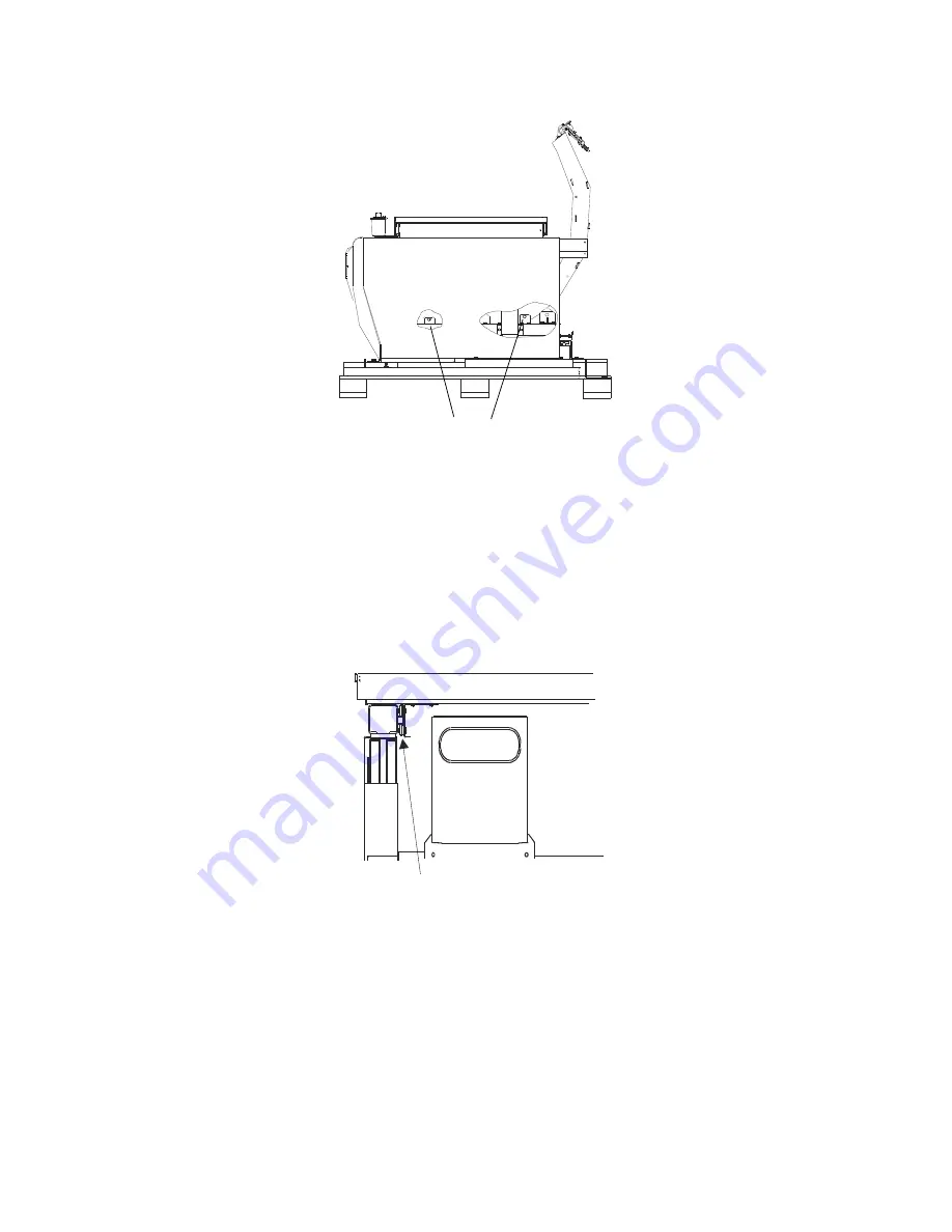
Figure 3-8. Shipping Bracket Locations (A and SL)
7. Disconnect the ribbon cable from the Arm R Motor Controller board.
8. Remove the Arm Y bearing blocks at the rear of the arm.
9. Remove the bracket that connects the C-arm to the Arm Y belt.
10. Lift the C-arm carriage up and out of the scanner unit.
11. Tape, or tie wrap, the bearing blocks to prevent them from sliding off the end of
the rail.
Figure 3-9. Table Locking “L” Bracket Location
C-Arm Shipping Brackets
Table Locking Bracket
Summary of Contents for DISCOVERY A
Page 52: ...Discovery QDR Series Technical Manual 2 30...
Page 55: ...Discovery QDR Series Technical Manual 3 3 Figure 3 2 System Dimensions for Discovery C...
Page 56: ...Discovery QDR Series Technical Manual 3 4 Figure 3 3 System Dimensions for Discovery SL...
Page 144: ...Discovery QDR Series Technical Manual 4 22...
Page 188: ...Discovery QDR Series Technical Manual 5 22...
Page 228: ...Discovery QDR Series Technical Manual 6 16...
Page 248: ......


