Discovery QDR Series Technical Manual
4-6
4. Hit the
<Esc>
key to return to the Discovery Main screen.
5. From the Discovery Main Menu screen, select
Utilities|Service Utili-
ties|SQDRIVER
.
6. At the CARM$$$$> prompt, type
move_ap100
(to move the Aper-
ture Plate right) or
move_aper_rel –100
(to the move Aperture Plate left) until
the Alignment Pin is both vertical and perpendicular to the Aperture Plate. (Place
the block on the base plate next to the pin and compare the pin to the vertical sur-
face of the block to see if the pin is perpendicular).
7. Type
exit <Enter>
to return to the Discovery Main Screen.
8. Start the X-Ray Survey Utility by selecting
Utilities|Service Utilities|X-Ray
Survey
(see “X-Ray Survey” on page 9-1 for information on the utility).
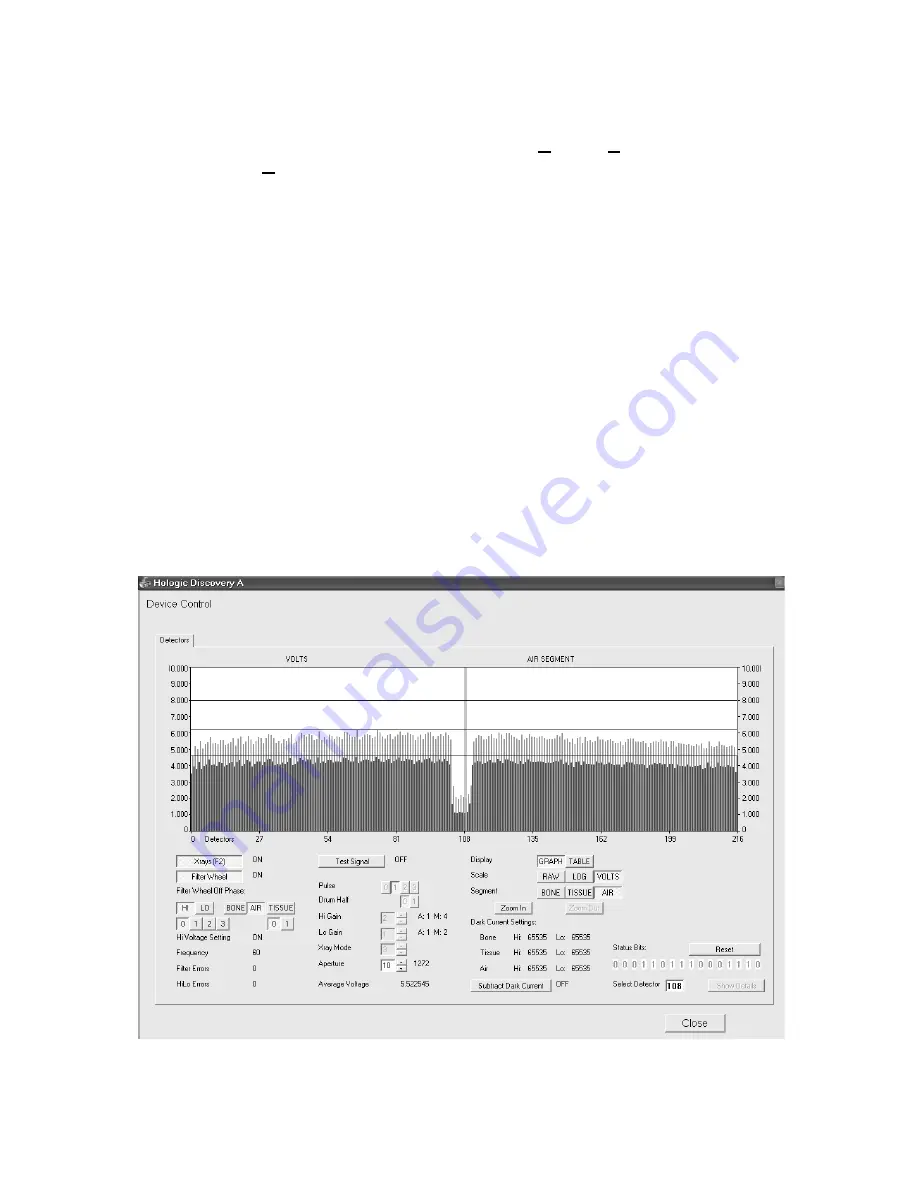
9. Do not change this Aperture setting (set to 10), the Hi gain setting (set to 2), the
Lo gain setting (set to 1) or the X-ray mode setting (set to 3).
10. For Display, click
Graph/
11. Click X-ray (F2) to turn on x-rays.
The correct display should show a flat graph with an amplitude of approximately 5.5 volts
with alignment fixture installed (approximately 6.5 volts with alignment fixture removed).
If the beam alignment is not correct, perform the following beam alignment procedure.
Summary of Contents for DISCOVERY A
Page 52: ...Discovery QDR Series Technical Manual 2 30...
Page 55: ...Discovery QDR Series Technical Manual 3 3 Figure 3 2 System Dimensions for Discovery C...
Page 56: ...Discovery QDR Series Technical Manual 3 4 Figure 3 3 System Dimensions for Discovery SL...
Page 144: ...Discovery QDR Series Technical Manual 4 22...
Page 188: ...Discovery QDR Series Technical Manual 5 22...
Page 228: ...Discovery QDR Series Technical Manual 6 16...
Page 248: ......


