MAINTENANCE
7-10
Lock Frames
d
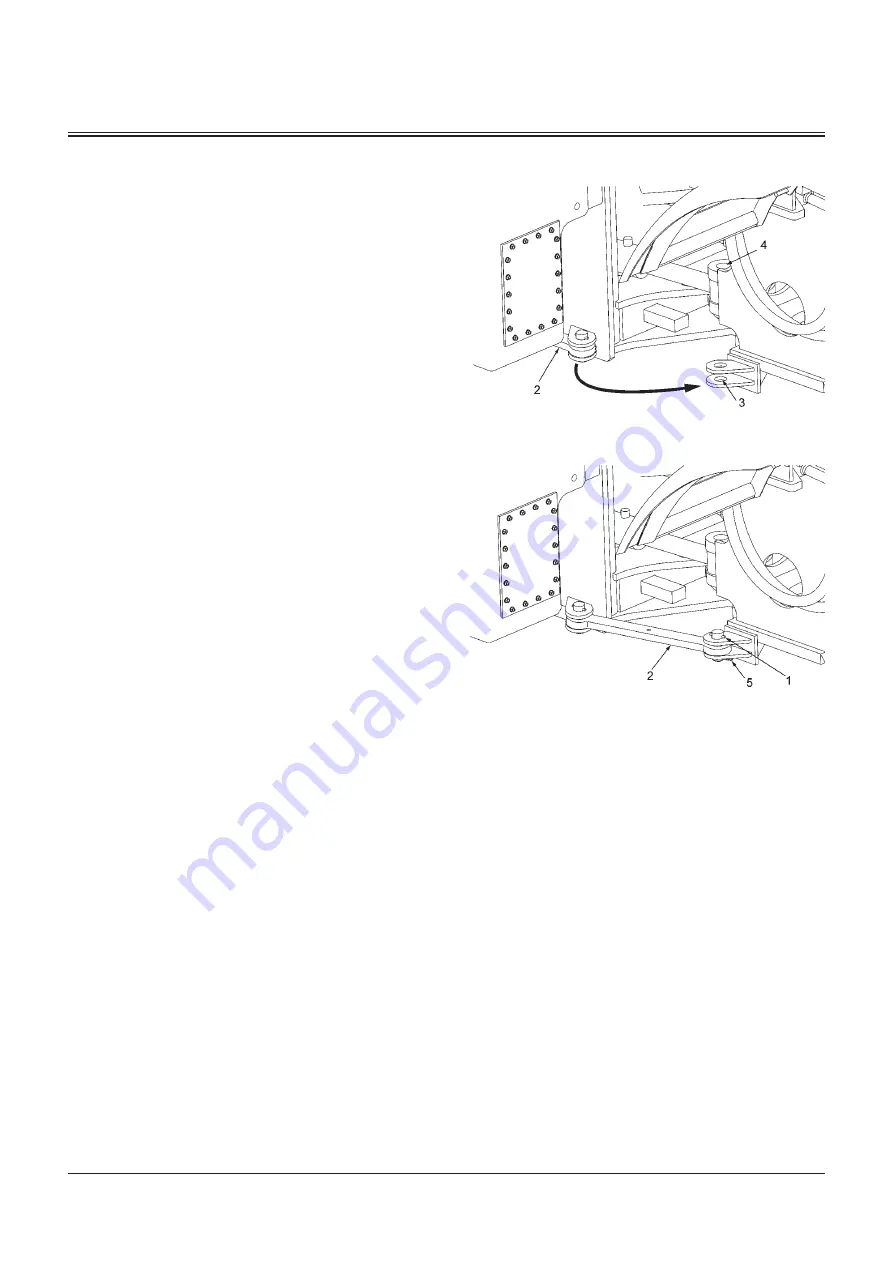
WARNING: Before beginning to work near the
frame center hinge (4), install articulation lock bar
(2) to securely lock and prohibit movement between
the front and rear frames. Avoid accidents due to
unexpected movement of the machine.
1. Align the front and rear frame centers with each other.
2. Remove β-form pin (5) to remove set pin (1) from the
rear frame hole.
3. Pull out and rotate articulation lock bar (2) to align it
with the front frame hole (3).
4. Install set pin (1) into the front frame hole (3) and the
articulation lock bar tip end hole. Install β-form pin (5) to
lock the articulation lock bar (2) in position.
90Z7-7-9-1
90Z7-7-9-2
Summary of Contents for ZW 310-6
Page 4: ......
Page 10: ...CONTENTS MEMO ...
Page 14: ...INTENDED USE 2 MEMO ...
Page 57: ...SAFETY SIGNS S 43 ZW310 6 SS 3777 2 ...
Page 59: ...SAFETY SIGNS S 45 ZW330 6 92Z7B S 40EU ...
Page 246: ...BREAK IN 2 2 MEMO ...
Page 280: ...DRIVING MACHINE 4 20 MEMO ...
Page 460: ...MAINTENANCE 7 146 MEMO ...
Page 464: ...MAINTENANCE UNDER SPECIAL ENVIRONMENTAL CONDITIONS 9 4 MEMO ...
Page 468: ...STORAGE 10 4 MEMO ...
Page 474: ...TROUBLESHOOTING 11 6 MEMO ...
Page 498: ...INDEX 14 6 MEMO ...
Page 502: ...CONFORMITY MEMO ...
Page 506: ......


