background image

6-81 

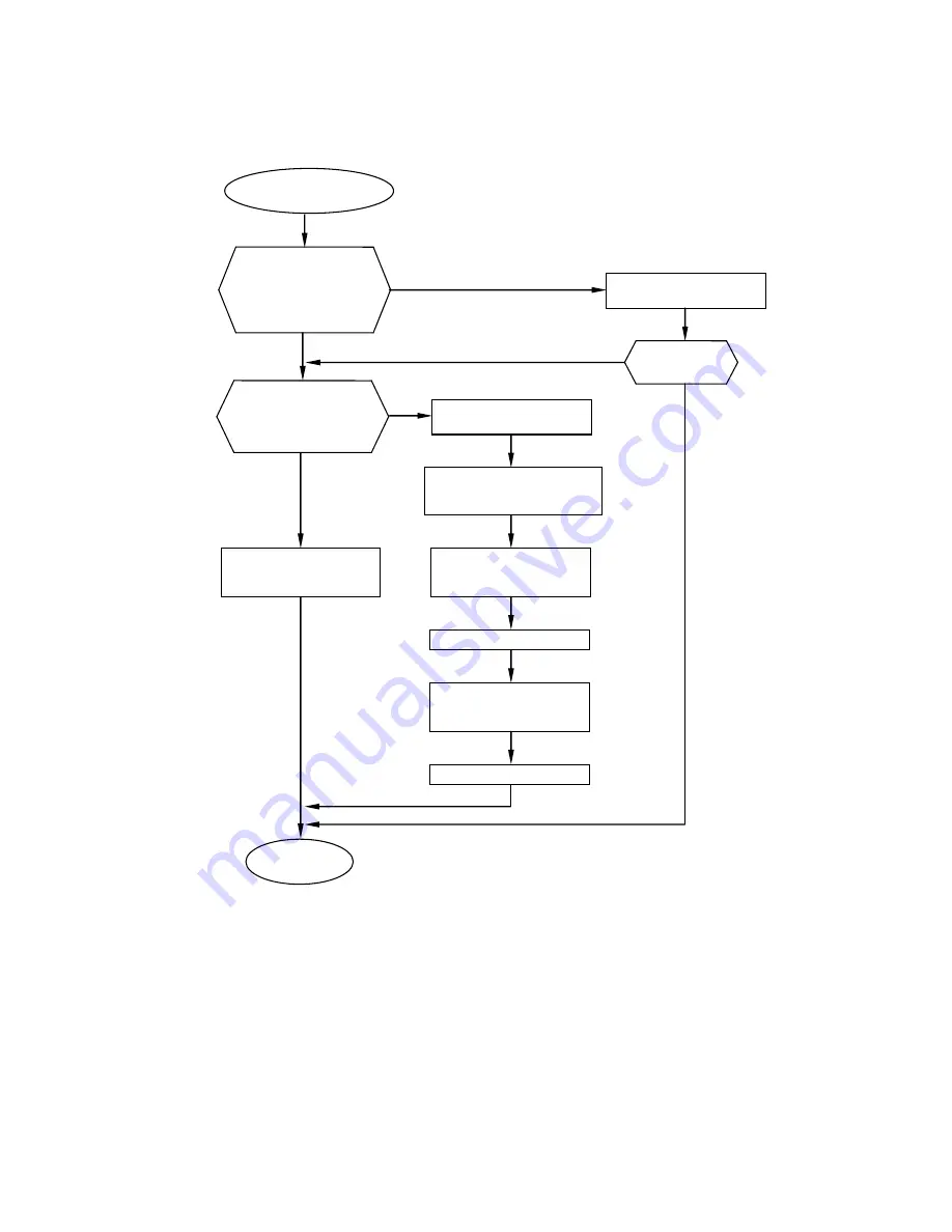
        6.4.20    Makeup Level Sensor Broken (2)


                    (Follow the same procedure for 

“Makeup Low Warning 2” and   

“Makeup Low Fault 2”.)


[Caution]   
1. When this warning “Makeup Level Sensor Broken (2)” is issued and the cause of this warning is not removed, the 

other warning of “Makeup Low Warning 2” will be issued in one(1) hour. Furthermore, “Makeup Low Fault 2” will 
be issued in another one (1) hour, and then IJP will be stopped. 

 
2. Ink ejection is available even though IJP is stopped by the warning of “Makeup Low Fault 2”. However, if the cause 

of this warning is not removed, “Makeup Level Sensor Broken (2)” will be issued again. 

 
3.  If  the  Makeup  cartridge  is  replaced  without  Makeup  ID  validated  properly,  the  state  of  level  sensor  becomes 

invalid and this fault may occur. 


Does the fault 
recur? 

Makeup Level 

Sensor Broken (2) 

Resume 

operation 

Go to “Level sensor 
confirmation” screen 
and check if all sensors 
in Makeup reservoir 
work properly. 

Yes


No


Replace the sensor block 
of Makeup reservoir. 

Yes


Does the Remaining 
Makeup Icon indicate 
“Replaceable Makeup 
Level”? 

Yes


No


Execute “Reservoir 
Makeup Drainage” 

Confirm if the Remaining 
Makeup Icon indicates 
“Replaceable Makeup Level”. 

Validate Makeup ID and 
replace the Makeup 
cartridge with new one. 

Execute “ Ink refill”. 

Validate  Makeup  ID  and 
replace 

the 

Makeup 

cartridge with new one. 

No


Execute “Ink drainage” to 
prevent  that  the  diluted 
ink is used. 

Execute “ Ink refill”. 

Summary of Contents for UX Twin Nozzle

Page 1: ...Service Manual HITACHI Printer UX Twin Nozzle Model Revision February 2017 Version A ...

Page 2: ... HITACHI IJ Printer Model UX for Dye Ink TYPE Nozzle Diameter UX D860W Standard Model Standard Character UX D 65μm ...

Page 3: ...10 2 3 4 Auto phase gain adjustment 2 13 2 3 5 Level sensor confirmation 2 15 2 3 6 Heating unit confirmation 2 18 2 4 Test of solenoid valve pump 2 20 2 5 Download 2 22 2 6 Calibration of viscometer 2 24 2 6 1 Calibration of viscometer 2 24 2 6 2 Operation test of viscometer 2 25 2 7 Circulation system environment setup 2 26 2 8 System reset 2 27 2 9 Back up 2 28 2 10 Unit information 2 29 2 11 H...

Page 4: ...rd 3 36 3 3 13 EZJ130 board Software option control board 3 38 3 3 14 EZJ129 board Software option terminal board 3 40 3 3 15 Multiple Power Supply 1 and 2 3 48 3 3 16 High Voltage Power Supply 1 and 2 3 51 3 3 17 DC fan 3 52 3 3 18 LAN communication function 3 52 3 3 19 RFID reader 3 53 3 3 20 Electrical Connection Diagram 3 55 4 Maintenance of Circulation System 4 1 4 1 Structure of Circulation ...

Page 5: ...ure 4 45 4 10 1 Ink Reservoir replacement 4 45 4 10 2 Makeup Reservoir replacement 4 47 4 11 Solenoid Replacement Procedure 4 49 4 12 Troubleshooting when Fault Occurs in Viscometer 4 52 4 12 1 Viscometer removal procedure 4 52 4 12 2 Disassembling and washing viscometer 4 54 4 12 3 Viscometer assembly procedure 4 55 4 12 4 Viscometer attaching procedure 4 55 4 12 5 Replacing thermistor 4 56 4 13 ...

Page 6: ...J135 replacement 5 11 5 8 Nozzle replacement 5 12 5 9 Nozzle Orifice Cleaning 5 15 5 10 Thermistor replacement 5 17 5 11 Deflection Base Replacement Procedure 5 19 5 12 Head base Replacement Procedure 5 23 5 13 Head Cable Replacement Procedure 5 26 6 Troubleshooting 6 1 6 1 Troubleshooting List 6 1 6 2 Faults Ink stop type 6 5 6 3 Faults Print stop type 6 47 6 4 Warning conditions printing continu...

Page 7: ... personal injury or death if the warning against performing an incorrect handling procedure is ignored CAUTION is used to indicate the presence of a hazard which may cause personal injury or property damage if the warning against performing an incorrect handling procedure is ignored Pictograph Examples The symbols are used to indicate precautions including those related to potential warnings to be...

Page 8: ...provided per print head If extraneous noise enters the printer it may malfunction or break down For maximum noise immunity observe the following installation and wiring precautions Ensure that 100 to 120 VAC or 200 to 240 VAC power cables are not bundled with other power supply cables Insulate the printer main body and print head so that they do not come into direct contact with the conveyor or ot...

Page 9: ...nk particles in a beaker for a printing test for example use an electrically conductive beaker and connect the beaker securely to the ground Do not let the tip of the printing head enter the beaker Ink particles used for printing are electrically charged An ungrounded beaker has a gradually rising charge possibly catching on or causing a fire Use an AC voltage of 100 to120 V or 200 to 240 V only a...

Page 10: ...hen wipe it off again If you wish to clean the casing of the printer with wiping paper impregnated with makeup be sure to do so with the power off Attempting to clean it when the power is on will cause vapors of ink or makeup to enter the printer possibly catching on or causing a fire When the cleaning is over open the maintenance cover and make sure that no makeup has entered and no vapors remain...

Page 11: ...f there is any spillage immediately wipe it clean using a cloth moistened with makeup Since the vapor pressure of the makeup is generally high if the ambient temperature is high such as in the summer etc the internal pressure will rise and makeup could spurt out when the outside cover is removed Therefore when unplugging do not hold the bottle near your face place the can on a level surface open w...

Page 12: ...flush with warm or cold water and consult a physician While the printer is operating do not look into the ink ejection hole in the end of the print head Ink or makeup may enter your eyes or mouth or soil your hands or clothing If any ink or makeup enters your eyes or mouth immediately flush with warm or cold water and consult a physician Before servicing the printer be sure to stop the ink ejectio...

Page 13: ...ply with all appropriate regulations Consult the appropriate regulatory agency for further information The printer must be managed in compliance with all appropriate regulations Read and understand the appropriate Safety Data Sheet SDS before using any ink or makeup Ink and makeup must be handled in compliance with the Industrial Safety and Health Law and PRTR Law environmental contaminant dischar...

Page 14: ...y fingers If the touch panel is operated with metal and or sharp objects such as ball point pen it may malfunction or break down Keep all fire away Ink and Makeup are flammable All fire must be kept away from the machine Spilled Ink and Makeup must be wiped off and dried up immediately Caution when handling Ink Makeup Storage must comply with local regulatory requirements Read and understand Safet...

Page 15: ... Reportez vous au Mode d emploi et aGT Conseils de manipulation de chaque type d encre pour plus de détails When replaced with an incorrect type of battery the battery is in danger of exploding Be sure to replace the battery with the one specified by parts list When disposing of the battery lithium battery you must comply with local regulatory requirements Consult the appropriate regulatory agency...

Page 16: ...1 10 1 2 Structure of each part in the main body 1 2 1 External views 1 External views 2 External views Rear side Air purge Connection port Exhaust duct Connection port ...

Page 17: ...ppearance with inner cover removed Makeup cartridge bottle Makeup reservoir Inner cover Ink cartridge bottle Ink reservoir Lever handle Ink filter Recovery filter1 Main ink tank Recovery filter2 Lever handle Pressure adjusting screw ...

Page 18: ...ce1 Minus deflection electrode1 Charge electrode2 Plus deflection electrode1 Gutter1 Gutter2 Plus deflection electrode2 Minus deflection electrode2 Nozzle orifice2 Note Meaning of orifice plate lot number Position of lot number Orifice plate 6 A12345 Serial number Nozzle diameter 6 65μm ...

Page 19: ...rements in addition to those given above Standard UL CUL certified Rating 125 V 7A or more Plug NEMA5 15P Cable Type SJT 18AWG 60 C or higher Cable length 1 5 4 5 m Use the proper plug Be sure to ground properly Locate the equipment near an electrical outlet and arrange so it can be easily disconnected Use a power cable that is within the specified range Do not bundle the light electrical cable to...

Page 20: ...the electrical outlet before performing work Be careful not to get shocked when checking with the cover open Precautions concerning electrical shock Be sure to mount the inlet cover Wrap the attached cable seal around the power cable and set in the position shown in the figure Caution Cable seal Power cable Inlet base Inlet cover Side cover Inlet cover ...

Page 21: ...tridge bottle is set 5 Ink stream alignment For filling makeup path and adjusting ink stream position Stream alignment1 Stream alignment2 Technical Manual 6 5 Stream alignment NOTE 1 When the makeup is not ejected from the nozzle even though the ink stream alignment is conducted the check valve in the makeup pump may be drying clogging Refer to 4 14 Troubleshooting Procedure for the Circulation Sy...

Page 22: ...andard value of the ink Technical Manual 6 9 Adjusting the pressure 10 Adjustment of excitation voltage Touch screen operation automatic setting Service Manual 2 3 1 Excitation adjustment 11 Adjustment of APH gain Touch screen operation automatic acquisition Service Manual 2 3 4 Auto phase gain adjustment 12 Setting of excitation voltage Confirm the actual print quality and the ink drop mode and t...

Page 23: ...table Displays version of booting system program loader in parentheses next to the version display 10 Solenoid valve pump test Multiple operations of the solenoid valve can be carried out simultaneously 11 User environment setup Displays Product Speed Matching Error Arabic pattern variation Minimum character height value Signal detection in target sensor filtering Print Overlap Fault Check Add ite...

Page 24: ...2 2 Service personnel maintenance mode setup procedure 1 Printing description screen is displayed 2 Press LOGIN The login user select screen is displayed LOGIN ...

Page 25: ...ustomer to the customer Caution After completion of service maintenance work be sure to return to the user maintenance mode The service personnel maintenance mode is canceled by setting of Service maintenance to protect on Password protection menu When the power is turned off the service personnel maintenance mode is automatically canceled When in service personnel maintenance mode the Touch scree...

Page 26: ...user selection screen 2 Press System environment setup on the second page of the maintenance menu The system environment setup screen is then displayed 3 Modify the setting values Note This item is automatically reset to the initial value when ink type is changed 4 When setup is complete press Back The screen returns to the maintenance menu Note When changing the ink type Ink concentration control...

Page 27: ...el maintenance mode refer to 2 1 Setting of service personnel maintenance mode When you make adjustment or operation check of EZJ125 board turn IJP power OFF once and then remove EZJ 134 board with fixing bracket attached Before the operation check is started attach Oscilloscope probes in advance to TP12 Charge signal and TP14 Excitation signal on EZJ125 board Refer to EZJ125 board external view i...

Page 28: ...tation voltage is automatically adjusted inside the IJ printer The excitation voltage is gradually increased and the adjustment is completed at 360 V 20V p p Excitation adjustment is automatically completed within 90 seconds 4 When completed the processing status is displayed to be Ended 5 If automatic adjustment fails the Manual adjustment key is displayed Proc status In progress Proc status Ende...

Page 29: ... insufficient 4 Replacement parts are out of order EZJ133 EZJ125 EZJ134 board nozzle head cable 5 EZJ125 board work A and EZJ 125 work B is faultily installed the wrong way around When you press Manual adjustment and manually input the excitation voltage adjustment value the excitation voltage value is increased or decreased Check the waveform of TP14 excitation voltage Nozzle 1 on the EZJ125 boar...

Page 30: ...enu is then displayed 2 Press Charge voltage confirmation The Charge voltage confirmation screen is then displayed The voltage for confirmation is output for 3 minutes For information on changing to the service personnel maintenance mode refer to 2 1 Setting of service personnel maintenance mode Adjust oper checkout Charge voltage confirmation N1 Execution takes 3 minutes Abort Proc status In prog...

Page 31: ...ake sure it is within the range of DC250V 15V When confirmation is completed press Abort and you can stop work before 3 minutes elapse Charge voltage Waveform of charge voltage confirmation GND level For the position of the board and test pins refer to 3 3 5 EZJ125 board and 3 3 6 EZJ134 board ...

Page 32: ...ance menu set the service personnel maintenance mode on the login user selection screen The adjustment operational checkout menu is then displayed 2 Press Phase margin test The phase margin test screen is then displayed For information on changing to the service personnel maintenance mode refer to 2 1 Setting of service personnel maintenance mode Manual Start up HOME Back Adjust oper checkout Exci...

Page 33: ...use percentage Product speed matching The content of printing is as described below A B C 1 2 3 Printed phase Printed phase which is set at present Display data Prints according to print conditions contents currently set for print target data 3 Print phase Each Nozzle Automatic update Prints print phases in sequence from 0 to 15 f Total of 16 prints per cycle Specified phase Print phase can be spe...

Page 34: ...tance of less than 15mm during the test Example 6 7 A B C 1 2 3 6 9 A B C 1 2 3 7 7 A B C 1 2 3 7 9 A B C 1 2 3 8 7 A B C 1 2 3 8 9 A B C 1 2 3 9 7 A B C 1 2 3 9 9 A B C 1 2 3 a 7 A B C 1 2 3 a 9 A B C 1 2 3 Range of print phase of Nozzle 2 which is set at present Print contents A B C 1 2 3 A B C 1 2 3 Printed phase Printed phase which is set at present 16 phase in total a phase determined to be s...

Page 35: ...rinter is in Drop adjust or Standby state 1 Press Adjustment operational checkout on the maintenance menu If Adjustment operational checkout is not displayed on the maintenance menu set the service personnel maintenance mode on the login user selection screen The adjustment operational checkout menu is then displayed 2 Press Auto phase gain adjustment The auto phase gain adjustment screen then app...

Page 36: ...gure 5 When the automatic adjustment is not normally completed or the wave form is abnormality confirm that the periphery of the gutter part is made dirty with ink or makeup When dirtiness or the like is present clean the periphery of the gutter part surely dry it and then perform the automatic adjustment again Numerical values of the auto phase gain value can also be input by a ten key To the val...

Page 37: ...Sensor 3 5 Ink reservoir Sensor 1 6 Sensor 2 7 Sensor 3 8 Makeup reservoir Sensor WHITE 9 Sensor RED Conduct this test in Stop or Standby state Level sensor confirmation of Initial 1 Sensor 1 Sensor 2 and Sensor 3 can NOT be conducted in Standby state It is recommended to conduct the Level sensor confirmation in Stop state Main ink tank Makeup reservoir Ink reservoir sensor 2 sensor 3 Initial leve...

Page 38: ...g to the service personnel maintenance mode refer to 2 1 Setting of service personnel maintenance mode Back Adjust oper checkout Level sensor confirmation Main ink tank Proc status In progress Ink reservoir Makeup reservoir undetected Back Too high OF Sensor detected Sensor detected Sensor 1 detected Sensor 2 detected Sensor 3 detected Initial 1 detected WHITE RED Manual Start up HOME Back Adjust ...

Page 39: ...nsor 1 The sensor is not detecting the level Ink is present Cartridge replacement can NOT be made Sensor 2 The sensor is not detecting the level Ink is present Cartridge replacement can NOT be made Sensor 3 Ink Low Warning appears Ink is present Cartridge replacement can be made Makeup reservoir Sensor WHITE Float UPPER The sensor is not detecting the level Makeup is present Cartridge replacement ...

Page 40: ...s not displayed on the maintenance menu set the service personnel maintenance mode on the login user selection screen The Adjustment operational checkout screen is displayed For information on changing to the service personnel maintenance mode refer to 2 1 Setting of service personnel maintenance mode Manual Start up HOME Back Adjust oper checkout Excitation adjustment Charge voltage Confirmation ...

Page 41: ...hether the heating unit is activated or deactivated 3 When Activate is pressed the heating unit turns ON Heating unit temperature rises The heating unit state is displayed as Activated 4 When the Deactivate is pressed the heating unit turns OFF Heating unit temp Nozzle1 11 Deactivated Activate Adjust oper checkout Heating unit confirmation Ambient temperature 10 Deactivate Abort Proc status In pro...

Page 42: ...mp operation Multiple solenoid valves can be operated simultaneously Only displays operation state Operations such as opening and closing the solenoid valve cannot be performed User maintenance mode Carries out confirmation of solenoid valve and pump operation One solenoid valve at a time is operated 1 Press Solenoid valve pump test on the maintenance menu The solenoid valve pump test screen is th...

Page 43: ...mp operating frequencies of UX Twin nozzle machine are different from those of UX Single nozzle machine Caution The pumps and solenoid valve can be operated simultaneously however operate them with care when the solenoid valve are turned on while pump is activated because it is not a steady operation ...

Page 44: ...rams You can confirm version of each program on the screen 1 The maintenance menu is displayed If Prev menu Next menu is not displayed on the maintenance menu set the service personnel maintenance mode on the login user selection screen 2 Mount USB memory containing system data For precautions when replacing the EZJ128 board refer to 3 2 1 EZJ128 board For precautions when replacing the EZJ133 boa...

Page 45: ...d the screen returns to the service maintenance screen 5 After downloading remove the USB memory Note Occasionally IJ printer does not recognize the USB memory at download procedure please make sure following things before download to avoid such problem Use initialized USB memory with FAT16 or FAT32 when copying system data to USB memory Confirm the USB memory can be used for download with your ma...

Page 46: ...rd the coefficient value or data backup is recommended The coefficient value is recorded in the memory on EZJ128 board So at the replacement of EZJ128 the calibration with new ink will be required in case that the value is not recorded nor made a backup When the calibration of viscometer is performed continuously for a number of times ink temperature within the viscometer increases and the accurac...

Page 47: ...t be registered when Cancel is pressed instead of OK key Standard value of the viscometer calibration 1200 to 2200 The value stated above is a reference There will be no problem even if the coefficient value displayed is other than stated above as long as data of Plunger falling time keeps within a similar range OK Cancel the previous calibration Exec time 2018 07 07 11 30 the current calibration ...

Page 48: ...surement Automatic stir out of Operation Disable It does not stir it Enable It performs the stirring in the device every 24 hours 1 Press Circulation environment setup Start Continue on the second page of the circulation control menu of maintenance The Circulation system environment setup screen is then displayed Caution 1 Under ordinary circumstances the default setting of ink concentration contr...

Page 49: ... on the login user selection screen 2 Press System reset on the second page of the maintenance menu The confirmation message is then displayed 3 Press OK Please wait is displayed After the completion of the system reset turn the printer OFF and then back ON after 10 seconds For work after System reset Please execute work according to 3 2 1 EZJ128 board controller board 12 13 of replacement procedu...

Page 50: ...ating time print count various usage time logging data viscosity data ink automatic replenishment data circulation control data fault warning history entry trace data Difference of copy target data between maintenance modes User maintenance mode Service personnel maintenance mode Types of data Backup IJ printer USB memory Data copy USB memory IJ printer Backup IJ printer USB memory Data copy USB m...

Page 51: ...t Board information Displays board mounting state Model key language key Upgrade key Option board RFID Reader Displays version of RFID Reader To control ink and makeup usage time limit set Ink and makeup usage time limit to Enable and input the lot number displayed on the bottle label If used after the 1st day of the month following date of manufacture specified usage limit a warning is displayed ...

Page 52: ...ept language key Display information Language key Y Normal J Language key B All language Installed N Fault Key is detected but the content of key is wrong Y Language key A Expect Japanese Installed Unmounted Undetected N Language key installed Different serial number Not installed or invalid language key A Indirect export machine For information on changing to the service personnel maintenance mod...

Page 53: ...et sensor filtering Disable Target sensor is off during target sensor filtering Repeat print does not stop Sensor chattering happens during target sensor filtering Normal printing Enable Target sensor is off during target sensor filtering Repeat print stop Sensor chattering happens during target sensor filtering Improper Sensor Position fault occur 5 Print overlap fault Check Disable Print Overlap...

Page 54: ...rt the print items will be automatically added 2 Add Items Process The print items will be added Column by Column using the format of the last column such as the number of lines and the character size If there be created the extra Column s and the print item s can t be added in units of Column the print item of the single line 5x8 5x7 character size will be added Please see below the examples when...

Page 55: ...ine Transmission Since the print data is re structured by adding the items if the print start signal is input right after the data transfer the error Print data changeover in progress will occur Please input the print start signal 400ms after the data is transferred 2 Print Data Recall Transmission The response performance will change whether this function is used or not However if the number of r...

Page 56: ...aracter orientation Reverse print Print signal type Print data changeover Char Size menu 1 signal ON OFF ON transition Reverse direction printing right justified left justified print complete print in progress Disable Enable 5x8 5x7 Change mode OFF forward ABC User environment setup Prev set tings Next set tings Char Size menu 2 Excitation V ref warning Product speed matching error 9x8 9x7 Disable...

Page 57: ...um character height User environment setup Prev set tings Next set tings 00 0 50 Arabic pattern variation method2 method1 Stop 2018 07 07 12 45 Com 0 Print Overlap Fault Check Add items in online mode Disable Enable Disable Enable Disable Restriction of Character width setting Disable Enable ...

Page 58: ...iary functions The language selection screen is then displayed If Change language is not displayed set to service personnel maintenance mode on the login user selection screen 3 Press Change language and select the desired language Selected language is then registered in place of already registered language 4 Select language from registered languages Display language is then changed 5 Select input...

Page 59: ...mode Languege1 Input mode 1 English Thai Vietnamese Simple Chinese Local language Japanese Local language 2 Traditional Chinese Local language 3 Korean Local language 4 Japanese Local language English Thai Vietnamese Simple Chinese Local language 5 Traditional Chinese Local language 6 Korean Local language 7 Traditional Chinese Local language English Thai Vietnamese Simple Chinese Local language 8...

Page 60: ...al Communication Error S 072 Calendar Content Inaccurate 023 SYSTEM OPERATION ERROR S 073 Ink expiration time management 024 Ink Heating Unit Over Current 074 025 Ambient Temperature Sensor Fault 075 External Communication Error 032 026 Print Controller Cooling Fan Fault 076 External Communication Error 033 027 Print Data Changeover Error C 077 External Communication Error 034 028 Print Data Chang...

Page 61: ...al Communication Error 021 194 Unknown Print Data 118 External Communication Error 022 119 External Communication Error 023 200 No Ink Concentration Control 120 External Communication Error 024 201 Print Data Settings Notice 121 External Communication Error 025 122 External Communication Error 026 209 Power Restoration Procedure 123 External Communication Error 027 210 USB Memory Error 124 Externa...

Page 62: ...r and install the EZJ129 board EZJ130 board 2 Turn on the power 3 Insert the USB memory which IJ printer system data is stored 4 Press Option setup at the second page of the service maintenance work screen If Prev menu Next menu is not displayed on the maintenance menu set the service personnel maintenance mode on the login user selection screen When a USB memory which IJ printer system data is st...

Page 63: ...ion of the setup the screen returns to the service maintenance screen 7 After the completion of setup remove the USB memory 8 Check the function of the software option HOME Back 04 Special communication A 05 External signal A 08 Barcode reader connection Option setup Disable Enable Disable Enable Disable Enable ...

Page 64: ...ing Model Set Value Time of preparing 65um UX D Standard Approx 5 5ms Please note when Short is set and continuous printing was performed at frequent intervals printing quality may drop Print quality is maintained if print standby time is saved Standard O N Print target sensor signal O F F Approx 7ms Approx 7ms Print specifications screen Printing operation Printing Printing ...

Page 65: ... change button Disable No button for Standby and Ready mode switching Enable Display the button for Standby and Ready switching Status background color can be selectable by status color Status color pattern list Status background color IJ printer Status Status background Pattern A White Stop Green Standby Starting Ink heating Stopping Service Drop adjust Cover open Blue Ready Red Fault Pattern B W...

Page 66: ...hree digits stand for Fault Warning log code The leftmost digit stands for nozzle number s Message Name of the message Info1 Code of cause of Fault Warning occurrence or the number of times that Product Speed Matching Error Warning was issued Info2 Code of detailed cause of Fault Warning Info3 Reserved Info4 Reserved Ver Software version Nozzle No Nozzle where Fault or warning occurred 1 Nozzle 1 ...

Page 67: ...orted and Skipped Note Ink refill etc is saved as Aborted and Skipped due to detection of the initial level of the main ink tank even it is normally completed Result 2 Aborted Result 3 Completed with failure Aborted step No Number of the step which was Aborted and Skipped Info1 Operation status during special processing within the Circulation sequence Info2 Operation status during special processi...

Page 68: ...eplenish ink for Dot count Minute Second Makeup replenishment To an initial level Time to replenish makeup to Initial level Minute Second Ink replenishment To an initial level Time to replenish ink to initial level Minute Second Finish time Time when the Automatic Replenishment completed Initial level status Initial level detection when Automatic replenishment started 0 Not detected 1 Detected Res...

Page 69: ...Fall 1 to Fall 5 Measurement value 1 to 5 of plunger falling time 5 times Average falling time Machine Inside Temperature Temperature inside the machine Ink temperature measured by the sensor in the viscometer Average Standard ink viscosity at 100 ink concentration Calculated by the Ink viscosity Ink viscosity Ink viscosity Average of falling time x Coefficient Standard viscosity x100 H viscosity ...

Page 70: ...e Time Information 002 Current time change 2018 08 28 8 15 40 2010 07 21 16 00 03 Calendar Time control Same as Current time Clock system 24 24 Record timing When Current time is changed on Date Time setup screen Logging contents Settings of Before change After change of Current time Calendar time control and Clock system Code Sequence name Code Sequence name 001 Power turned on time 015 Ambient t...

Page 71: ...d Logging contents Settings of Before change After change of the Serial number Code Sequence name Date Time Information 008 Unmatched model key 2018 08 28 8 15 40 EZJ128 0013141105600D8B0 000000010000000 found 2018 01 28 00 00 00 model 5A13141105600D8B000 0000000000000 Record timing When the model key was detected as unmatched Logging contents Information of EZJ128 board date and time when Unmatch...

Page 72: ...git of year of manufacture 0 9 cd Month of manufacture 01 12 efgh Serial number 0000 9999 2 abcd e a Month of manufacture A 1 B 2 H 8 I 9 J 10 K 11 L 12 bc Date of manufacture 01 31 d Last digit of year of manufacture A 1 B 2 I 9 J 0 e Order of manufacture 1 9 3 abcde f a Month of manufacture A 1 B 2 H 8 I 9 J 10 K 11 L 12 bc Date of manufacture 01 31 d Internal numbering S e Last digit of year of...

Page 73: ...currence date of mismatch 2 Serial numbers of EZJ128 and EZJ121B Board of Language key 3 J Japanese can be set W Japanese can NOT be set Code Sequence name Date Time Information 018 Time of preparing for print 2018 08 28 8 15 40 found 2018 08 28 13 00 00 key 01 step 07 Record timing When Upgrade recovery is detected Logging contents 1 found Initial occurrence date of mismatch 2 key The number of u...

Page 74: ...e Time Information 025 The Radio Law is approved 2018 08 28 8 15 40 No Yes Record timing When setting of The Radio Law is approved was changed on System environment setup screen Logging contents Settings of Before change After change of The Radio Law is approved Code Sequence name Date Time Information 026 Tag reading of cartridge is approved 2018 08 28 8 15 40 No Yes Record timing When the settin...

Page 75: ... 2 Insert a rescue memory USB into the slot 3 Turn on the power Download procedure start automatically 4 Turn off the power when the download is completed 5 Take the rescue USB from the USB port 6 Turn on the power the message of Model key Information Difference will show up Turn the Power OFF and then back On after 10 seconds 7 Turn off the Power Insert the system data USB memory then turn on the...

Page 76: ...ern Original Usable Standard character Original Usable User environment setup Original Usable System environment setup Original Usable Communication environment Original Usable Periodic replacement part mgmt Original Usable Operation setup Original Reinstall Ink operating time Cumulative op time and Pint count Alarm history All blank Excitation V up data Excitation V ref 11 Usable Touch screen set...

Page 77: ...xternal signal control and interior of inlet cover at primary power side Be sure to turn OFF the power when you open the cover of the controller part the engine part and I O part And then wait for 10 seconds at least before accessing those parts Be careful against the electric shock when you perform adjustment with the cover opened since the high voltage is applied in the unit Caution against elec...

Page 78: ... against electric shock Caution When you open the maintenance door with the surface of the main body is wet be sure to remove the water on the main body to prevent water intrusion inside of the main body EZJ125 board EZJ134 board EZJ133 board DC fan EZJ138 board Battery EZJ119 board Available as option Fixing screw M3x2 EZJ127 board Fixing screw M3x2 Spacer for fixing protection cover ...

Page 79: ...tric shock be sure to turn off the power supply and wait for at least 10 seconds and pull the power cable out of the outlet before opening the cover It is not necessary to remove Inlet cover or Inlet base when accessing to interior of the side cover Caution against access to side cover inside Glass fuses 2pcs are installed Do NOT touch those Glass fuses to prevent electric shock Caution against el...

Page 80: ...The LCD panel for screen display Y 4 TOUCH PANEL RX Input system for display screen operation Y 5 CR BATTERY N Back up batteries are for EZJ126 board and EZJ128 board Y 6 Model Key Store the unit specific information Y 7 Language Key Add the language outside the support area OP 8 Upgrade Key Upgrade the function of the standard model N 9 RFID READER MD PARTS Read information from IC tag Y 10 DC fa...

Page 81: ...and then press Enter 9 When data download is completed message of Model key Information Difference will be shown And then turn the main power OFF and ON to restart IJP 10 After download is completed execute System reset on the second page of the service maintenance screen Caution When replacing EZJ128 board system data USB memory is required System data USB memory is a memory that stores the lates...

Page 82: ...or Viscosity coefficient input 2 6 1 Calibration of viscometer or input ink viscosity coefficient on 2 10 Unit information 7 Adjustment of auto phase gain value 2 3 4 Auto phase gain adjustment 8 Excitation voltage setting Technical manual 6 10 Excitation V Adjustment 9 Readjustment of auto phase gain value 2 3 4 Auto phase gain adjustment 10 Editing print data Instruction manual 4 Creation and pr...

Page 83: ...4 Connector for LCD harness Connector for EZJ133 board CN8 Connector for battery connection Fixing screw 3 locations NO Fixing screw Fixing screw 3 locations Fixing screw 3 locations Connector for USB F1 F2 IC34 F3 Connector for EZJ 114 board C55 Board name board revision Board revision C or before NOT available for Model UX D Twin nozzle Board revision D onward Available for Model UX D Twin nozzl...

Page 84: ...Note at the replacement Battery external view CN8 Caution Before replacing the battery be sure to turn main power switch OFF Confirm that CN8 is surely inserted or date backup cannot be performed After EZJ128 board is replaced restart IJP to adjust the date and time if the date and time are displayed wrongly gain if it shows wrong date or time With respect to the setting of date and time refer to ...

Page 85: ...ry voltage is less than 3V before disposal Caution Si vous remplacez avec un mauvais type de batterie elle risque d exploser Assurez vous d utiliser une batterie indiquée dans la liste des pièces Lorsque vous jetez la batterie isolez la avec du ruban adhésif etc 1 Mélangée à d autres métaux ou batteries une batterie non isolée peut chauffer et provoquer un incendie ou une explosion 2 Ne pas jeter ...

Page 86: ... the actuator like flipping it upward 2 How to insert the FFC Insert the FFC with its contact surface facing down Also insert the FFC straight to the connector Figure 3 Figure 4 Insert the FFC straight to the connector Incorrect insertion at shown in figure 4 could cause conduction failure or the actuator breakdown Caution when inserting FFC Contact surface Figure 3 Actuator Figure 1 Do not unlock...

Page 87: ...ng screws 2 2pieces and then remove EZJ128 board with Board mounting plate 4 Remove Backlight harness from LCD 5 Remove EZJ136 board with cables connected from LCD 6 Remove Fixing screws 3 2pieces 2pieces and then remove LCD 7 Replace LCD with a new one and then reassemble all the removed parts and cables in reverse order of the procedures above Tighten Fixing screws 2 2pieces and Fixing screws 3 ...

Page 88: ...nd install a new touch panel by following the procedures in reverse order When inserting the touch panel connection cable into the connector on EZJ128 board hold both sides of the cable rein forced as shown in the drawing to prevent folding the cable Caution when inserting or extracting touch panel connection cable Touch panel Maintenance door Wear the gloves when replacing the touch panel Handlin...

Page 89: ...etal spacers 2pcs and the fixing screw 1 piece from EZJ125 board 8 Remove the protective cover for high voltage power supply and then remove EZJ133 board 9 Remove the model key which is installed on old EZJ133 board and re install it on the new EZJ133 board to be replaced 10 Mount EZJ134 board with fixing metal plate attached Note that clamp the wires of CN1 and CN3 on the back of the metal plate ...

Page 90: ...l spacers 2pcs and the fixing screw 1 piece from EZJ125 board 8 Remove the protective cover for high voltage power supply and then remove EZJ133 board 9 Remove the model key which is installed on old EZJ133 board and re install it on the new EZJ133 board to be replaced 10 Mount EZJ134 board with fixing metal plate attached Note that clamp the wires of CN1 and CN3 on the back of the metal plate and...

Page 91: ...to phase gain value 2 3 4 Auto phase gain adjustment 8 Excitation voltage setting Technical manual 6 10 Excitation V adjustment 9 Readjustment of auto phase gain value 2 3 4 Auto phase gain adjustment 10 Editing print data Instruction manual 4 Creation and printing of message 11 Setting of substitution rules Instruction manual 4 10 3 Print by substituting a different character for the date Substit...

Page 92: ...25 CN5 Connector for EZJ125 board CN15 Connector for Language key CN25 Connector for Model key Connector for EZJ128 LED1 CN27 Connector for RFID reader TP17 Print in progress TP23 APH signal TP24 PTC signal CN10 Connector for EZJ130 board TP22 Sensor N TP21 Encoder N CN14 Connector for battery connection TP5 PGND CN2 Connector for Power supply1 connection CN28 Connector for Power supply 2 connecti...

Page 93: ...perly Or date backup cannot be performed After replacing the battery on the EZJ133 board turn main power switch ON the and confirm the date and time Perform set up again if it shows wrong date or time Caution With respect to the setting of date and time refer to the Instruction manual 6 2 setting the Date and Time Caution When the type of battery replaced is wrong there will be a danger of explosi...

Page 94: ...nguages Remarks Type A All languages other than Japanese Available only in the countries other than Japan Type B All languages Unit serial number and additional language information are stored in language key Languages outside the support area are not avairable if the serial number stored in the language key does not match the serial number in the unit When either one of the conditions below is me...

Page 95: ...istered including Japanese A Indirectly exported machine Corresponding to countries other than Japan 3 3 5 EZJ125 board Nozzle1 drive board Function Control of nozzle charging voltage control excitation voltage APH detection PTC control etc is performed Setting of switch check point LED display etc Setting of switch Nozzle size 65µm SW1 Set both bits up SW2 Set both bits up Check point LED Referen...

Page 96: ... and then remove EZJ125 board 8 Replace the EZJ125 board with a new one and then reassemble the removed parts in the reverse order of the procedures above 9 Set up DSW1 and DSW2 according to the nozzle diameter 10 Confirm the charging voltage 11 Adjust Excitation adjustment and Auto phase gain adjustment 12 Check if the respective nozzle can conduct print operation properly Protective cover Spacer...

Page 97: ... order to avoid an electric shock be sure to turn off the power and wait for at least 10 seconds before accessing the EZJ125 board Caution against an electric shock T1 The color of coil tape A work Blue B work Yellow DSW1 Hexagonal spacer Hexagonal spacer Serial number Board revision A A is placed in the end of the serial number NOT available for model UX D Twin nozzle Board revision B B is placed...

Page 98: ...he connector of CN1 and CN3 hold the socket housing and pull them out in straight Replacement procedures of EZJ134 board 1 Turn off the power 2 Remove the protective cover As the drawing below push the hook of fixing spacer with finger and pull up the protective cover Three spacers 3 Remove the connectors from CN2 and CN4 Connector on board Hold the socket housing Mark Protective cover Spacer for ...

Page 99: ... spacer with fingers and then remove EZJ134 board upward with pushing the hook 6 Replace the EZJ134 board and then install the each part by the procedures above in reverse order 7 Set up SW1 according to the nozzle diameter 8 Confirm the charging voltage 9 Perform Excitation adjustment and Auto phase gain adjustment 10 Check if the respective nozzle can conduct print operation properly EZJ134 boar...

Page 100: ...ge is applied In order to avoid an electric shock be sure to turn OFF the power and wait for at least 10 seconds at least before accessing the EZJ134 board Caution against an electric shock With respect to the excitation adjustment refer to 2 3 1 Excitation adjustment With respect to the excitation adjustment refer to 2 3 1 Excitation adjustment With respect to the auto phase gain adjustment refer...

Page 101: ...can be selected by SW1 Power supply can be selected by SW1 7 Encoder signal Totem pole Input 8 Encoder signal Open collector NPN Input 9 Ground for Encoder 10 Ready Output Open collector NPN only 11 Signal ground 12 Fault Output 13 Warning Output 14 Deflection voltage ON OFF signal Input NPN PNP can be selected by SW2 15 Reciprocative print signal Input 16 Run signal Input 17 Reset signal Input 18...

Page 102: ...PN PNP Input signal Print stop Reciprocative printing Deflection voltage ON OFF Run Reset Stop Input Output NPN Input Output PNP SW2 Both bits are put downward Both bits are put upward Input NPN Output PNP Input PNP Output NPN SW2 Set only the right bit upward Set only the left bit upward SW1 Set content Setting of factory default Bit1 Setting is performed according to the specification of the enc...

Page 103: ...input PNP is ON it is lit LED12 Reset input NPN When Reset signal input NPN is ON it is lit LED13 Stop input PNP When Stop signal input PNP is ON it is lit LED14 Stop input NPN When Stop signal input NPN is ON it is lit LED15 Print output PNP When Print in progress Print completed signal output is ON it is lit LED16 Online output PNP When Online output is ON it is lit LED17 Universal output 1 PNP ...

Page 104: ...rnal connection terminal block 1 TB1 Applicable cable size AWG26 to 16 Φ0 5 to 1 3 Wire coating to be stripped 8 to 9 mm SW1 Fixing screw SW2 Fixing screw LED1 LED23 TP6 Terminal block TB1 Serial number Last digit A 1 Push 2 Insert Twist the wires ...

Page 105: ...part of cabinet Pin number Name Input Output Remarks 1 NC No connection 2 RD Input 3 SD Output 4 DTR Connected to DSR on IJ printer 5 SG Ground 6 DSR Connected to DTR on IJ printer 7 RTS Connected to CTS on IJ printer 8 CTS Connected to RTS on IJ printer 9 NC No connection The control signals are looped back on EZJ127A board External device IJ Printer SG 5 SG 8 CTS Input 7 RTS Output DSR Input 4 D...

Page 106: ...3 30 Circuit diagram of EZJ127A board ...

Page 107: ...Remove Multiple power supply1 Refer to step 1 to 6 of Replacement procedures of multiple power supply in 3 3 15 Multiple power supply1 and 2 4 Remove the connectors of CN1 CN2 and CN3 on EZJ138 board 5 Remove the fixingscrews 6 pcs by using driver φ2 shorter than 160mm 6 Replace EZJ138 board and then reassemble the removed parts in the reverse order EZJ138 board external view CN4 B side Connection...

Page 108: ...ard is replaced EZJ113 board external view AC power is supplied to EZJ113 board In order to avoid an electric shock turn off the power and wait for more than 10 seconds pull the plug out of socket and then access EZJ113 board Caution against an electric shock CN2 Connection to AC power input CN3 Connection to EZJ114 board CN1 Connection to multiple power supply CN4 Connection to EZJ133 board Fixin...

Page 109: ...fixing spacers and one fixing screw 4 Insert the connectors of CN1 CN2 CN3 and CN4 in place 5 Place the ground wire terminal around the connecting position then close the side cover When closing the cover be sure not to pinch the wires 6 Be sure to connect the ground wire terminal to the ground wire connecting position Inside of side cover CN4 CN3 CN1 CN2 EZJ113 When you turn the main power switch...

Page 110: ...s 4 locations and remove the side cover And then remove the ground wire It is not necessary to remove the inlet base nor inlet cover AC power is supplied to the EZJ139 board In order to avoid an electric shock turn off the power and wait for more than 10 seconds pull the plug out of socket and then access the EZJ139 board Caution against an electric shock Side cover CN1 Connection to multiple powe...

Page 111: ...r be sure not to pinch the wires 6 Be sure to connect the ground wire terminal to the ground wire connecting position 7 Check if IJP starts up properly by turning power ON If CN1 and CN3 on EZJ139 board are connected wrongly the screen display can not be lit up In this case check if those connectors are connected properly or not Inside of side cover CN4 CN3 CN1 CN2 EZJ139 When turn main power swit...

Page 112: ...in power switch OFF Before replacing the board be sure that the electric power is NOT supplied to the wires connecting to TB2 EZJ119A board external view Replacement procedures of EZJ119A board 1 Turn off the power and open the top cover 2 Remove the connector CN7 of EZJ119A board 3 Remove the two fixing screws 4 Replace with a new EZJ119A board and then reassemble the parts removed in reverse ord...

Page 113: ...loses depending on whether IJ printer state is Ready or not When NC contact break contact is used Ready output signal is disabled The path between the TB2 terminals opens as shown in the table below regardless whether IJ printer state is Ready or not When NO contact make contact is used Ready output signal is disabled The path between TB2 terminals 1 and 3 opens and the path between TB2 terminals ...

Page 114: ...ed Replacement procedures of EZJ130 board 1 Turn off the power and open the maintenance cover 2 Remove the connectors CN1 CN2 of EZJ130 board 3 Remove one fixing screw 1 piece 4 Remove CN4 connector which goes to EZJ133 board and then replace EZJ130 board with new one 5 Reassemble the removed parts in the reverse order of the procedures above CN2 Connection to EZJ129 board CN1 Connection to EZJ129...

Page 115: ...3 39 Setting of SW Check point Display of LED etc SW1 Setting of input signal Calendar stop signal Reserve input SW1 Both of bits are set upward Set the right bit downward Mark Mark ...

Page 116: ...to 8 EZJ129 external view Replacement procedures of EZJ129 board 1 Turn main power switch OFF and open the top cover 2 Remove the connectors CN8 CN9 CN4 and wires connected to TB3 3 Remove two fixing screws and then replace EZJ129 with a new one 4 Reassemble the removed parts in reverse order of the procedures above 5 Perform the settings of SW4 to SW8 Inside the top cover upper part of cabinet Fi...

Page 117: ...No connection Pin number Name Input Output Remarks 1 NC No connection 2 RD Input 3 SD Output 4 DTR Output 5 SG Ground 6 DSR Input 7 RTS Output 8 CTS Input 9 NC No connection External device IJ Printer SG 5 SG 8 CTS Input RTS 7 RTS Output CTS 6 DSR Input DTR 4 DTR Output DSR Input RD 2 SD RD Output SD 3 Cable length maximum 15m FG Send data Receive data Circuit board side connector 9 pin D sub conn...

Page 118: ...message number signal bit 4 Input 14 Data message number signal bit 3 Input 15 Data message number signal bit 2 Input 16 Data message number signal bit 1 Input 17 Data message number signal bit 0 Input 18 Calendar stop Reserve of input Input Signal can be selected by EZJ130 SW1 NPN PNP can be selected by SW8 19 Reserve of signal ground 20 Reserved input Input 21 Reserved input Input 22 Reserved in...

Page 119: ...tted from host Setting Photocoupler operation Voltage level at TB3 pin 8 ON OFF ON Bit 6 Reserved Set to OFF OFF Bit 7 Power supply for Print target detector Vision Sensor OFF In case of using external power supply ON Bit 8 Sets Power supply ON In case of using Power supply OFF In case of not using Power supply ON SW5 SW5 Description Factory default setting Bit 1 Reserved Default setting is show i...

Page 120: ...f bits are put upward Set the right bit to down ward SW8 Switches NPN PNP settings of Data message number signals and Input signals and Internal External power supply Factory default setting is both bits are set upward When supplying power from IJ Printer When using external power supply NPN I F PNP I F NPN I F PNP I F SW8 Both bits are set upward Set the left bit downward Set the right bit downwa...

Page 121: ...t PNP is ON it is lit LED14 Data message number signal bit 4 NPN When the data message number signal bit 4 input NPN is ON it is lit LED15 Data message number signal bit 4 PNP When the data message number signal bit 4 input PNP is ON it is lit LED16 Data message number signal bit 5 NPN When the data message number signal bit 5 input NPN is ON it is lit LED17 Data message number signal bit 5 PNP Wh...

Page 122: ...signal bit 11 input PNP is ON it is lit LED30 Strobe signal NPN When the strobe signal input NPN is ON it is lit LED31 Strobe signal PNP When the strobe signal input PNP is ON it is lit LED36 Signal during calendar Updating PNP When the Signal during calendar Updating PNP is ON it is lighted LED37 Signal notifying Completion of signal input PNP When the Signal notifying Completion of signal input ...

Page 123: ...3 47 Circuit diagram of EZJ129 board ...

Page 124: ... supply 1 Turn off the main power and wait for more than 10 seconds Then pull the plug out of socket 2 Remove the fixing screws 6 positions and remove the side cover It is not necessary to remove the inlet base nor inlet cover Caution against an electric shock In order to replace the multiple power supply it is necessary to access inside the side cover which has the area where AC power is applied ...

Page 125: ... 16 high voltage power supply Ground wire yellow and green EZJ139 board CN3 Connector for Multiple power supply 1 Fixing screw for Multiple power supply 2 1 piece EZJ134 board EZJ125 board EZJ133 board High voltage power supply 1 and 2 Metal plate for spacer fixing protective cover Remove the fixing screws 2pcs circled Multiple power supply 1 High voltage power supply 1 and 2 are removed Fixing me...

Page 126: ...harness and connectors on EZJ133 134 139 and 125 board 9 Check if IJP is started up properly by turning power ON If CN2 and CN28 onEZJ133 board are connected wrongly the screen display can not be lit up In this case check if those connected properly or not 10 Check if print operation can be made by respective nozzles by turning the main power switch ON Inside of maintenance cover With respect to t...

Page 127: ...er supply Fixing positions and method are the same for High voltage power supply1 and 2 6 Replace High voltage power supply with a new one and then reassemble the removed parts in the reverse order of the procedures above Check the clamping positions of the harnesses 7 Turn main power ON Check if the respective nozzle can conduct print operation properly Caution against an electric shock Be sure t...

Page 128: ... the main power and open the maintenance door 2 Remove the DC fan connector CN29 on EZJ133 board Remove the two fixing screws of DC fan 3 Replace with DC fan and reassemble the removed parts in reverse order of the procedures above 3 3 18 LAN Communication function Function Ethernet communication unit using IJ printer communication library Note at the replacement Be sure to turn off the main power...

Page 129: ...er as shown in the drawing below Push the Hook of the fixing spacer by finger and then pull up Protective cover For Two spacers 4 Remove RFID reader harness from CN27 connector of EZJ133 board Protective cover EZJ125 board Spacer for fixing protective cover 2 pieces Push Hook Pull up Protective cover CN27 EZJ133 board RFID reader harness EZJ125 board LAN cable connecting port of LAN Relay Harness ...

Page 130: ...eet be sure to follow three 3 points below Replace Front beam sheet with a new one Confirm that there is NO adhesive remaining on the Front beam Attach the new Front beam sheet by pushing the Front beam sheet to the left side of the convexed frame When you attach Front beam be sure that the electrical wires or cables are NOT to be pinched between any parts Danger of Electrical shock Front beam she...

Page 131: ...3 55 3 3 20 Electrical Connection Diagram ...

Page 132: ...ness UX Y L 1N4ZE0501A Sensor harness UX Y M 3N4ZM4183A High voltage harness H assembly Y N 2N4ZL2144A High voltage harness S UX Y O 1N4ZE0066A I O harness UX Y P 2N4ZL2139A Connection harness MV UX Y Q 2N4ZL2140A Connection harness S UX Y R 1N4ZE0067A OP I O harness UX OP S 2N4ZL2154A Relay output harness assembly Y T 2N4ZL8304A Connection harness MV UXT N U 2N4ZL8305A Connection harness UXT N V ...

Page 133: ...3 57 Clamp position inside the maintenance cover Clamping position of wire harness Clamp number Clamping wire harness number O R I Y D E Z AD AE AF Back of metal plate for fixing EZJ134 board ...

Page 134: ...after EZJ134 board fixing metal is removed 1 17 16 4 5 15 12 13 10 3 2 7 9 8 14 6 11 Cases of wrong connection Refer to the table of Connector numbers and Identifying method of Harness Symptom caused by wrong connection No 2 No 3 Screen display is NOT lit up after main power is turned ON No 4 No 5 Warning of Ambient temperature Sensor Fault occurs after main power is turned ON No 6 No 7 Print posi...

Page 135: ...a partition the system is roughly divided into an ink circulating area the front side of the equipment and a driving part area the rear side of the equipment Circulation unit front view Ink circulating area Driving part area Makeup cartridge Unit door Ink filter Main ink tank Exhaust duct Ink cartridge Circulation Unit Recovery pump unit Pressure sensor Viscometer Makeup filter Circulation filter ...

Page 136: ...unit MV3 Recovery valve MV4 Viscosity valve MV7 Makeup valve MV2 Replenishment valve MV6 Pressure relief valve MV5 Circulation valve MV8 Cleaning valve MV1 Supply valve MV28 Cleaning valve MV25 Circulation valve MV23 Recovery valve Pressure sensor ...

Page 137: ...Self tapping screw M4X12 Viscometer etc Pump unit PBT G30 1 7 0 3 17 3 3 Circulation unit PBT G30 1 7 0 3 17 3 3 Ink main tank PBT G30 1 7 0 3 17 3 3 Self tapping screw M4X16 Solenoid valve Circulation unit PBT G30 1 7 0 3 17 3 3 Self tapping screw M4X30 Circulation unit Pump unit ADC12 aluminum 1 7 0 3 17 3 3 Self tapping screw B M3X10 ICU joint Pump unit PBT G30 0 5 0 1 5 1 1 Circulation unit Se...

Page 138: ...nance cover Reservoir Unit Remove Clamp Tube Cable Tube Cable Clamp CAUTION Carefully mount the Reservoir unit back to its place so that the piping tube of the recovery filter is not pinched After performing the task of pulling the Reservoir unit please make sure that the level sensor is functioning normally Fixing screws Pull out Reservoir Unit Reservoir Unit Inner cover B a a CAUTION Please do n...

Page 139: ...unit is pulled outside as indicated in the figure in step 4 of 4 1 2 Access to the parts on the front side of the equipment a The length of the recovery filter tubes is limited only approximately 330mm When the Reservoir unit is pulled outside remove the fixing screw 1 position first then hold the Recovery filter base with your hand to remove the Reservoir unit from its original position Carefully...

Page 140: ...Access method from the front 1 Perform 4 1 2 Access to the parts on the front side of the equipment and pull the reservoir unit out 2 Remove the fixing screws 2 pieces of the unit door and open the unit door Caution Take care not to cause the tubes to be caught Unit door Unit door ...

Page 141: ...4 7 2 Access method from the rear 1 Remove fixing screws 11 positions of the rear cover and detach it Rear cover These two screws can remain loosened ...

Page 142: ...ng the Drain Tube CAUTION When Air Trap is observed conduct Air removal until no Air Trap is observed Check the Level surface The Air Trap will not interfere with the operation of the printer Main Ink Tank Fixing screw Tube Lock K Tube Lock Q Tube Lock P Tube Lock G Tube Lock Drain Tube Main Ink Tank Yellow OFF Red 3 チ ュ ー ブ ロ ッ ク G Blue 2 Black G White 1 ...

Page 143: ... Ink filter 5 Remove the fixing screw 2 pieces and remove the filter clamp 6 Remove the joints of Recovery Tube and Drain Tube 7 Remove the Tube Lock Caution Put wiping paper under the main ink tank to avoid ink dripping on the floor etc 8 Remove the wire connecting part screws 5 positions of the liquid level sensor on the main ink tank Yellow OFF Red 3 Blue 2 Black G White 1 Main ink tank Fixing ...

Page 144: ... Solenoid Cable while above work is implemented 11 Remove the fixing screw 1 position and take out the main ink tank 12 Remove the tube locks 5 positions Caution Put wiping paper under the main ink tank for ink dripping Fixing screw Tube lock K Tube lock Q Tube lock P Tube lock G Tube lock Drain tube Main ink tank Hook Inner cover B Solenoid Cable Fixing screws Makeup reservoir ...

Page 145: ... When installing the Makeup Reservoir out the hook of the Makeup reservoir into the hole of the Reservoir base first 17 Perform Ink refill and make sure that there is no ink leak 4 2 3 Removal method of the Main ink tank lid Fixing screws Main ink tank Inner cover B Cautions when URGENT OVERHAUL of the Main tank is required Main ink tank can be overhauled by unfastening the screws on top Prepare a...

Page 146: ...Pressure reducing valve and a new O ring S 4 E 227 1 piece Caution Make sure to use O ring S 4 E 227 1 piece 5 Wet O ring S 4 E 227 with makeup and put it on the joint of the new Pressure reducing valve 6 Attach the new Pressure reducing valve in reverse order of the procedures above Caution When attaching the Pressure reducing valve make sure O ring S 4 E 227 is kept in place and it does not fall...

Page 147: ... joint 2 Wet the O ring with the makeup and then insert it into the connecting port of the circulation unit Caution If it cannot be inserted smoothly the O ring may have jammed and get stuck Perform the procedures starting from Step 1 again 3 Tighten the fixing screw Caution Do NOT over tighten the screw OR the screw may strip and keep on turning Procedure for removing the ICU joint only for Pump ...

Page 148: ...ion to ink dripping MV7 Execute Ink drainage Drain the ink of the main ink tank from the drain tube MV8 Execute Pressure relief No operation is required Pay attention to makeup dripping MV11 No operation is required Pay attention to makeup dripping No operation is required Pay attention to ink dripping MV12 Execute Pressure relief No operation is required Pay attention to ink dripping MV23 Execute...

Page 149: ... 15 Solenoid valve No Wire color Solenoid valve No Wire color Solenoid valve No Wire color MV1 Brown MV5 Green MV23 Orange MV2 Red MV6 Blue MV25 Green MV3 Orange MV7 Purple MV28 Gray MV4 Yellow MV8 Gray ...

Page 150: ...en install the new solenoid valve in reverse order of the procedures above Caution Securely set the O ring in the groove of the solenoid valve Pay extra attention not to cause the O ring to fall off or pinched Fixing screws 2 Positions Solenoid valve O ring S24 O ring4 7 E227 MV25 Green MV23 Orange MV28 Gray MV8 Gray MV7 Purple MV6 Blue MV5 Green MV4 Yellow MV3 Orange MV2 Red MV1 Brown ...

Page 151: ...4 17 7 Reset the time of the replaced solenoid to 0 on the Parts usage time management screen ...

Page 152: ...4 1 3 Access to the parts on the rear side of the equipment The reason is that the connector is located on the rear side of the equipment 4 Remove the connector of the pressure sensor 5 Remove the screws 2 positions that fix the pressure sensor The pressure sensor can be removed Caution Put wiping paper under the solenoid valve for ink dripping Connector for pressure sensor Pressure sensor Unit do...

Page 153: ...the new O ring with makeup and mount on the joint 8 Insert the pressure sensor to the joint and fix it with the fastener that was removed in step 6 Caution Use a new O ring Mount carefully so that the O ring does not fall out or is not pinched 9 Return the unit to its original state by performing the procedures in reverse order 10 Eject ink and make sure the ink pressure is normal Joint O ring 7 5...

Page 154: ...s on the rear side of the equipment The reason is that the connector is located on the rear side of the equipment 4 Remove the connector of the pressure sensor 5 Remove the screws that fix the Solenoid valve base Connector for pressure sensor Unit door Pressure sensor Caution When unplugging the connector be sure to pull out straight Do not twist off or it may break the connector Fixing screws for...

Page 155: ...by pulling Caution Put wiping paper under the Pressure sensor for ink dripping Pull forward If the ink was accidentally spilled quickly wipe it off with wiping paper etc In addition do not close the maintenance cover until you confirm that the wiped part completely get dry CAUTION Pressure sensor Fastener Joint Connector for pressure sensor ...

Page 156: ...e sensor to the joint and fix it with the fastener that was removed in step 7 Caution Use a new O ring Mount carefully so that the O ring does not fall out or is not pinched 10 Return the unit to its original state by performing the procedures in reverse order 11 Eject ink and make sure the ink pressure is normal O ring Joint ...

Page 157: ...f the equipment and draw out the reservoir unit 4 Perform 4 1 3 Access to the parts on the rear side of the equipment 1 Access method from the front and open the unit door Caution Be careful not to catch the tubes 5 Remove the tubes 15 positions that are connected to the circulation unit Caution Be careful about ink dripping 6 Remove the wire harness from the clamps 6 positions ...

Page 158: ...then install the new Circulation unit in reverse order of the procedures above 10 Replace motor cover on the new Circulation unit Refer to step 4 of 4 8 4 Motor replacement 11 Remove and replace the plug in the new Circulation unit with the joint Refer to the drawing above 12 Perform Makeup refill and then Ink refill Make sure that any ink leak or makeup leak is not occurring at any places Fixing ...

Page 159: ...ccess to the parts on the rear side of the equipment 1 Access method from the front and open the unit door Caution Be careful not to catch the tubes 4 Remove the wire harness from the clamps 6 positions 5 Disengage the connectors of the electrical parts 6 positions pressure sensor viscometer 3 positions level sensor and float sensor 5 positions 1 position ...

Page 160: ...he door Remove the tube from the ICU joint which is shown by dashed line Remove the other tubes 3 positions by loosening the tube locks 7 Remove two screws which are located topside These screws are fixing ICU Fixing plate to Pump unit Pull out connectors 6 positions Tubes Tube Fixing screws Fixing screws Door Pump unit Fixing screw Fixing screw ICU fixing plate ICU fixing plate Pump unit ...

Page 161: ...Clean the portion stained with ink and make sure that the O rings 4 positions are securely mounted in the concaves of the lower side circulation unit Then install the new pump unit in reverse order of the procedures above 10 Perform Ink refill and adjust the pressure Make sure that there is no ink leak 11 Reset the pump time to 0 on the Parts usage time management screen Fixing screws 8 positions ...

Page 162: ...rts on the rear side of the equipment 1 Access method from the front and open the unit door Caution Be careful not to catch the tubes 3 Remove the wires from clamps 6 positions 4 Remove the Motor connection connector Drive unit Motor connection connector Clamp Clamps Pump Unit circulation unit Motor cover ...

Page 163: ...Pump unit Caution When the Drive unit is removed the springs on the Pump head 4 pieces are freed causing the internal parts diaphragms elongated To avoid this put the Drive unit back to its place approximately within 60 minutes 7 Attach the new Drive unit in reverse order Pump unit Fixing screws Fixing screws Drive unit Drive unit ...

Page 164: ...ment procedure and remove the drive unit 4 Remove the fixing screws 2 positions and remove the pump head Example The following figure below indicates the case of the makeup pump head removal Caution Be careful not to lose the O ring O ring Pump head Makeup pump Supply pump Makeup pump Circulation pump Recovery pump Fixing screws 2 pieces ...

Page 165: ...e new O rings 2 pieces Be careful not to cause the O ring to fall off or pinched Refer to the figures below for identifications of 4 kinds of pump heads 6 Reset the pump time to 0 on the Parts usage time management screen Supply pump head Makeup pump head Circulation pump head Recovery pump head 1 position 2 positions 3 positions 4 positions ...

Page 166: ...e equipment 1 Access method from the front and open the unit door Caution Be careful not to catch the tubes 3 Remove the connector from the Motor 4 Remove the fixing screws 4 positions of the Motor and Motor cover Drive unit Motor connection connector Motor cover Fixing screw 2 pcs Motor Motor cover Fixing screw 2 pcs ...

Page 167: ...3 5 Install the new motor in reverse order of the procedures above CAUTION Beware of Motor Rotation When checking the motor with IJ printer door opened watch the motor rotation and or being caught by motor ...

Page 168: ...ragms elongated To avoid this put the drive unit back to its place approximately within 60 minutes 3 Remove the fixing screws 2 positions and take out the pump cover 4 Referring to 4 8 4 Motor replacement remove the motor 5 Hold the D cut of the drive shaft by spanner and remove the hex head bolt near the gear 6 Shift the drive shaft as shown by an arrow and remove the shaft from the bearing Fixin...

Page 169: ...e Use Silicone Grease G501 made by Shin etsu Chemical Co Ltd 4 8 6 Recovery pump2 drive unit replacement procedure 1 Turn off the power supply 2 Perform 4 1 3 Access to the parts on the rear side of the equipment 1 Access method from the front and open the unit door Caution Be careful not to catch the tubes 3 Remove the wires from clamps 2 positions Turn counterclockwise Gear Clamp ...

Page 170: ...very pump unit 6 Pull the Recovery pump unit forward Motor connection connector Recovery pump unit Fixing screw Fixing screw Mark AA If the ink was accidentally spilled quickly wipe it off with wiping paper etc In addition do not close the maintenance cover until you confirm that the wiped part completely get dry CAUTION Recovery pump unit Pull forward ...

Page 171: ... 2 Turn off the power supply 3 Perform 4 8 6 Recovery pump2 drive unit replacement procedure and remove the drive unit Caution When the drive unit is removed the springs on the pump head 4 pieces are freed causing the internal parts diaphragms elongated To avoid this put the drive unit back to its place approximately within 60 minutes 4 Remove the fixing screws 2 positions and remove the pump head...

Page 172: ...erse order of the procedures above Caution Make sure to use new O rings 2 pieces Be careful not to cause the O ring to fall off or pinched Refer to the figures below for identifications 6 Reset the pump time to 0 on the Parts usage time management screen Recovery pump head 4 positions ...

Page 173: ...ts on the rear side of the equipment 1 Access method from the front and open the unit door Caution Be careful not to catch the tubes 3 Remove the connector from the Motor 4 Holding the Recovery pump unit by hand remove the fixing screw 1 piece of Recovery pump unit Fixing screw Fixing screw Motor connection connector ...

Page 174: ...tions of the motor 6 Mount the new motor by reverse order of the procedures above CAUTION Beware of Motor Rotation When checking the motor with IJ printer door opened watch the motor rotation and or being caught by motor Motor Fixing screw ...

Page 175: ... causing the internal parts diaphragms elongated To avoid this put the drive unit back to its place approximately within 60 minutes 3 Remove the fixing screws 2 positions and take out the pump cover 4 Referring to 4 8 8 Recovery pump2 motor replacement procedure remove the motor 5 Hold the D cut of the drive shaft by spanner and remove the hex head bolt near the gear Fixing screws Pump cover Motor...

Page 176: ...the bearing 7 Rotate the gear counterclockwise and remove the gear 8 Install the new gear in reverse order of the procedures above When installing coat the gear teeth with the silicone grease Use Silicone Grease G501 made by Shin etsu Chemical Co Ltd Turn counterclockwise Gear ...

Page 177: ...s filter and mount the new ones Replacement of makeup filter 1 2 Rotate the nut of the makeup filter and pull it out 3 Remove the used O ring and its filter by tweezers and mount the new ones 4 Reset the circulation filter time and or the makeup filter time to 0 on the Parts usage time management screen Second page of the circulation control screen Makeup filter Circulation filter Nut Filter O rin...

Page 178: ... makeup filter and pull it out 3 Remove the used O ring and its filter and mount the new ones 4 Reset the circulation filter time and or the makeup filter time to 0 on the Parts usage time management screen Second page of the circulation control screen O ring Filter Nut If the ink was accidentally spilled quickly wipe it off with wiping paper etc In addition do not close the maintenance cover unti...

Page 179: ...and drain the ink into a beaker out of the ink reservoir s opening for attaching the sensor block At the ink drainage put wiping paper under the beaker for possible ink dripping If there is still ink remaining in the ink cartridge bottle do NOT lift the lever handle 2 Turn off the power supply 3 Perform 4 1 2 Access to the parts on the front side of the equipment and draw out the reservoir unit Ca...

Page 180: ... with ink and then install the new ink reservoir in reverse order of the procedures above Caution When installing the Ink reservoir put the hook of the Ink reservoir into the hole of the Reservoir base first Fixing screws Inner cover INK Ink reservoir Hook Reservoir base Hook Reservoir base Ink reservoir ...

Page 181: ...ainage put wiping paper under the beaker for possible makeup dripping If there is still makeup remaining in the makeup cartridge bottle do NOT lift the lever handle 2 Turn off the power supply 3 Perform the procedures described in 4 1 2 Access to the parts on the front side of the equipment and pull the reservoir unit forward Caution Be careful not to catch the tubes 4 Remove the Sensor block from...

Page 182: ... with ink and the install the new Makeup Reservoir in reverse order of the procedures above Caution When installing the Makeup Reservoir out the hook of the Makeup reservoir into the hole of the Reservoir base first Fixing screws Inner cover SOL Hook Reservoir base Makeup reservoir Hook Reservoir base Makeup reservoir ...

Page 183: ...olenoids 1 Turn off the power supply 2 Follow the procedures described in 4 1 2 Access to the parts on the front side of the equipment and pull the Reservoir unit out 3 Remove the Fixing screw and remove Main ink tank Caution Be careful not to tip Main ink tank over 4 Remove the fixing screws 2 positions and remove the Makeup reservoir 5 Remove the Solenoid cable from the hook on the Inner cover B...

Page 184: ...enoid to be replaced and remove the solenoid cable 11 Put a new solenoid in reverse order of the procedures above Route the solenoid cable to the hook of the inner cover B Refer to the figure in step 5 for how to route the Solenoid Cable Caution When you install the solenoid do NOT pinch the wirings Color of solenoid cable of maintenance part is orange only and it is compatible with solenoid 13 an...

Page 185: ... B When installing the Makeup Reservoir out the hook of the Makeup reservoir into the hole of the Reservoir base first 13 On Solenoid valve Pump test screen confirm that the solenoid of ink side or Makeup side operates properly Lock engaged Lock pin comes OUT Lock Released Lock Pin pulled IN Be careful not to catch the cable Hook Reservoir base Makeup reservoir Hook Reservoir base Makeup reservoir...

Page 186: ...r Proceed to c if no recovery is made c Replace viscometer 2 Viscosity Readings Out of Range Estimated cause Ink adhered to the IN side of viscometer Troubleshooting Disassemble and wash viscometer Estimated cause Proximity sensor was faulty Troubleshooting Replace the proximity sensor If there is no recovery with the above troubleshooting replace the viscometer 3 Inside Temperature Too High Cause...

Page 187: ...k remaining inside before removing the viscometer A Turn power on B Use Solenoid Valve Pump Test screen of Maintenance menu to turn on the pump to MV4 in that order and operate them for at least 10 seconds The ink remaining in viscometer will return to the main ink tank C Turn power off 3 Unplugging connectors Caution Do not perform this work with power turned on Doing so will cause Viscometer Tem...

Page 188: ...cometer seep out to the wiping paper 3 Make sure that no ink remains in viscometer and then pull out the cylinder If ink remains it will soil the coil 4 Put the plunger and the cylinder which are removed in a beaker filled with makeup and wash them for at least 5 minutes using an ultrasonic washer Viscometer cover Three viscometer cover setscrews Coil Cylinder Plunger Thermistor setscrew Thermisto...

Page 189: ...g procedure 1 Set the O ring on the viscometer OUT side and use the setscrews 2 pieces to attach the viscometer to the circulation unit 2 Plug in the connectors 3 Connect the viscometer IN side tube mark G Caution After reassembly it may be necessary to replace the ink and or calibrate the viscometer When disassembling and washing during installation Calibrate the viscometer Ink replacement is NOT...

Page 190: ...g plate and then replace the thermistor Caution When installing the new thermistor moisten the O ring with makeup to prevent it from being damaged 3 Return the viscometer to its original position referring to item 4 12 4 Caution After replacing the thermistor it is necessary to replace the ink and calibrate the viscometer see 2 6 Calibration of viscometer ...

Page 191: ...ors 10 locations in the control area Caution When removing the print head connector which is connected to High voltage power supply loosen the screw of battery first and then remove Board base cover UXT Be careful not to lose the removed screw EZJ134 board EZJ125 board EZJ133 board Multiple power supply 1 Loosen M3x8 Battery Board base cover UXT EZJ133 board ...

Page 192: ...the print head CN3 CN3 CN5 CN1 CN2 CN7 CN36 CN38 Fixing screws The inside of a side cover FG line of printhead located on the downside Fixing screws EZJ134 board EZJ125 board EZJ133 board Multiple power supply 1 Power supply connector 2 locations ...

Page 193: ...elow at the front of Circulation unit Loosen the tube lock and pull out the tube Caution Apply wiping paper at the ends of the tubes for ink dripping Recovery line upper Mark A Recovery filter Circulation line Mark J Supply line Mark E Makeup line Mark R Recovery line Mark 7 Recovery filter2 ...

Page 194: ...e Fastener For reassembling refer to Cautions when Recovery filter base is removed described in step 4 of 4 1 2 Access to the parts on the front side of the equipment 7 Remove the tubes which were removed from the fixing clamps 8 Perform 4 1 3 Access to the parts on the rear side of the equipment and open the unit door 9 Remove the back cover Fixing screws 11 pieces Back cover These two screws can...

Page 195: ... 11 Rotate the Head H Clamp assembly by 45 degrees and pull the Head H Clamp Assembly out 12 Widen the Claws of Head H Clamp assembly and remove it from the harness of the print head Head H Clamp assembly Claws Head H Clamp assembly Makeup line Mark RR Circulation line Mark JJ Circulation line Mark HH ...

Page 196: ...cable the thickest cable shall be placed at the most right end when viewed from the rear of the printer Please see the figure above 15 Perform Ink Replenishment and adjust the pressure Make sure that there is no ink leak 16 Perform Excitation adjustment and Auto phase gain adjustment 14 wire cable shall be placed at the most right end Use Head H Clamp assembly which you removed bundling with new P...

Page 197: ...rainage are not completed within the specified time When the fault is not recovered by repeating startup and shutdown replace the supply pump head The check valve is dry or sticks The solenoid valve is operating but ink does not flow Refer to 4 15 Repairing method when the circulation route is dry or sticks The solenoid valve malfunctions MV1 malfunctions When Open is executed on Solenoid Valve Pu...

Page 198: ...t ink does not flow Refer to 4 15 Repairing method when the circulation route is dry or sticks Clogging in the orifice plate When backwash conducted makeup does not flow to the tube of circulation route Clean the orifice plate with ultrasonic cleaning Charging or drainage is impossible The supply pump malfunctions Follow the same descriptions as those of Ink in Nozzle 1 is not ejected The solenoid...

Page 199: ...xecuted on Solenoid Valve Pump Test screen no operation sound is produced Replace the solenoid valve MV28 Refer to 4 15 Repairing method when the circulation route is dry or sticks The ink pressure of Nozzle 1 does not increase The supply pump malfunctions Follow the same descriptions as those of Ink in Nozzle 1 is not ejected The solenoid valve malfunctions MV1 malfunctions When Open is executed ...

Page 200: ...eplacement Procedure Backwash is impossible Nozzle 1 The circulating pump malfunctions Follow the same descriptions as those of The supply pump malfunctions The solenoid valve malfunctions MV5 malfunctions When Open is executed on Solenoid Valve Pump Test screen no operation sound is produced Replace or repair the solenoid valve MV5 Refer to 4 15 Repairing method when the circulation route is dry ...

Page 201: ...ctions Follow the same descriptions as those of The supply pump malfunctions The solenoid valve malfunctions MV3 malfunctions When Open is executed on Solenoid Valve Pump Test screen no operation sound is produced Replace or repair the solenoid valve MV3 Refer to 4 15 Repairing method when the circulation route is dry or sticks The recovery route clogs Clogging in the recovery filter A lot of fore...

Page 202: ... flows out from the recovery route then change the blocking position to the downstream in the recovery route and find the place where the air is sucked in When the part in question is found disconnect the part Remove foreign materials if any and reconnect the part When the fault is not recovered replace the part The exhaust route clogs The exhaust tube of the main ink tank is clogged with dried in...

Page 203: ...y route is faulty The air is sucked from the connection somewhere in the recovery route Prepare the checking tube which is made by cutting PTFE tube Part name PTFE tube 2 3 Part No 451064 to the length of about 600mm and the beaker or the like containing water Replace the tube fixed to the Tube Lock 1 on the main ink tank with the checking tube and put the other end of the checking tube into the w...

Page 204: ...ulation route is dry or sticks The circulation route cloggs Clogging in the pipe or joint Back wash can be performed and MV4 operates properly Refer to 4 15 Repairing method when the circulation route is dry or sticks The viscometer malfunctions Other than above Replace or repair the Viscometer During Ink Refill the message Failure was detected in level sensor pump or solenoid valve is displayed o...

Page 205: ...4 71 Ink or makeup in each reservoir is in short supply Check if the warning message Ink Low Warning or Makeup Low Warning is displayed on the screen Replenish ink or makeup and restart ...

Page 206: ... abnormal Part Check method Criterion Pump motor 1 Operate the pump on the Solenoid Valve Pump Test screen 2 Measure the voltage at pin No 5 wire red 20 V DC or more Solenoid valve 1 Exchange the solenoid valve and or the connector with another normal solenoid valve and or connector 2 Set the solenoid value to Open on the Solenoid Valve Pump Test screen and check the sound An operation sound shall...

Page 207: ...oid valve pump test screen for 10 times or so If the operation sound is confirmed then restoration is complete If operation cannot be restored replace the solenoid valve 4 15 2 Repairing method for the supply pump 1 Remove the tube connecting block of the ink reservoir and then remove CV assembly After that connect hand pump with makeup in it to the pipe M 2 Operate the pump MV2 and MV6 in this or...

Page 208: ...hand pump Refer to 4 15 2 Repairing method for the supply pump Such a hard sticking which cannot be repaired with the hand pump will not occur 4 15 4 Repairing method for the circulation pump 1 Start the circulation pump by Start up or Eject ink 2 When the circulation pump is started operate it for about 10 minutes with the pressure adjusting screw turned completely clockwise to obtain the maximum...

Page 209: ...epair work is completed If the pump cannot be repaired by pump operation for 10 minutes replace the pump unit Recovery filter 2 1 Remove tube AA from MV23 Solenoid and then connect the tube to the hand pump which is filled with makeup 2 Start operating Pump 2 on the screen of Solenoid Valve Pump Test 3 Apply pressure on the hand pump 4 If makeup in the hand pump flows into Tube 5 the repair work i...

Page 210: ...then insert a metal pin or the like into the hole of the CV assembly The SUS ball which is firmly adhered to the O ring inside the CV assembly shall be separated CV assembly Tube connecting block Before insertion After insertion SUS ball O ring Pin Cross sectional view Stick part Enlarge 4 7mm Reference inserting dimension φ2mm ...

Page 211: ...r 2 Loosen the thumbscrew and remove the Intake fan cover 3 Remove the Air filter Note The Air filter has front and rear faces Set the filter with red mark being invisible Intake fan cover assembly Intake fan Thumbscrew Air filter Intake fan unit assembly Intake fan cover Air filter Red mark in rear Intake fan cover Thumbscrew 2 locations ...

Page 212: ... of Intake fan cover assembly 7 Pull out the harness and remove the Intake fan unit from two positioning bosses 8 Install the new Intake fan unit by reverse order of the procedures above Positioning bosses two locations Harness routing Fastening screws 4 locations Intake fan unit assembly Fastening screws 4 locations Intake fan harness connector 冷却ユニットクミ Intake fan cover assembly Intake fan unit a...

Page 213: ...air filter in every two times 1 Turn off the power supply 2 Remove the exhaust cover 3 Remove the fixing screws 4 locations the filter cover and the R air filter 4 Install the new R air filter by reverse order of the procedures above Exhaust cover Red mark Filter cover Fixing screws 4 locations Filter cover R air filter Stainless wire mesh filter The R Air filter has front and rear faces Place the...

Page 214: ...hen IJP is serviced at periodical maintenance please check the items below 1 Is there any wiring routed around the exhaust duct such as the power cord the electrical signal wirings etc Should there be dripping the wire cable coating may get cracked Please reroute the wiring and call customer s attention 2 Is there any track of the dripping Please propose a tray for dripping to customer There may b...

Page 215: ...culation control Reservoir Makeup Drainage 2 Perform the procedures of 2 to 7 of 2 Operating Procedure of 6 16 1 Process prior to long term shutdown in Technical Manual Note Use Makeup S100A for the procedure 6 a of 2 Operating Procedure of 6 16 1 Process prior to long term shutdown 3 Replacing the ink filter Refer to 6 7 Replacing the ink filter in Technical Manual 4 Replacing the recovery filter...

Page 216: ...ometer 8 Drain the used makeup Execute Reservoir Makeup Drainage Press Maintenance Ink Circulation Reservoir Makeup Drainage 9 Set the Makeup cartridge for Ethanol based ink 10 Perform the procedures which drain the remaining makeup S100A and refill with makeup for Ethanol based ink Perform the procedures of 2 to 6 of 2 Operating Procedure of 6 16 1 Process prior to long term shutdown in Technical...

Page 217: ...cated Shutoff valve MV29 Nozzle ground Nozzle 1 Nozzle excitation connector No mark is indicated Charge electrode Positive deflection electrode Negative deflection electrode Gutter Coupling Nozzle2 Nozzle excitation connector 2 Shutoff valve MV29 connector 2 Shutoff valve MV9 Heating unit connector No mark is indicated Nozzle 1 side Nozzle 2 side Nozzle 1 side Nozzle 2 side ...

Page 218: ...s shown in the following figures The customer should not attempt to run the cable himself herself The cable should be run by a service technician 1 Remove the 4 fastening screws Pull out the coupling approximately by 10 mm 2 Turn the cable by 90 3 Tighten the 4 fastening screws ...

Page 219: ...ethod 5 3 1 Gutter configuration 5 3 2 Replacement method 1 Remove the 2 fastening screws 2 The gutter base comes off The gutter and the gutter base are connected and cannot be disassembled Gutter Gutter base Fastening screws Gutter base O ring 2 2 ...

Page 220: ... Remove the head cover and the heater cover 3 Remove the nozzle lead wire and the air purge tube 4 Remove the screws of Coupling cover 2 locations and remove the coupling cover 5 Remove MGV holder and Nozzle IN joint holder Lead wire Coupling cover Nozzle IN Joint holder MGV holder Air purge tube Heater cover Head cover Screw of coupling cover MV29 MV9 Nozzle excitation connector 2 ...

Page 221: ...and new O ring 3 9 Perform the assembly after dipping the O ring in makeup and confirm that the O ring does not jump out of the hole 2 Attach the head cover and the heater cover MV9 MV29 Nozzle IN joint O ring 3 9 MGV filter O rings are inserted here When they are come off dip the O rings in makeup and perform the assembly ...

Page 222: ... Depressurize the printer 2 Remove the head cover and the heater cover 3 Disassemble the shutoff valve connectors 4 Remove the nozzle lead wire and the air purge tube MV29 Lead wire Shutoff valve connector No mark is indicated MV9 Shutoff valve connector 2 MV29 MV9 Air purge tube Not detachable Nozzle excitation connector 2 Nozzle excitation connector No mark is indicated ...

Page 223: ...mained in the heating unit remove it 8 1 Put the MGV filter O ring 3 9 O ring 2 2 and O ring 1 7 into the respective holes of the joint parts of new MV9 MV29 Perform the assembly after dipping the O ring in makeup and confirm that the O ring does not jump out of the hole Fixing screws Coupling cover Nozzle IN joint holder MGV holder MV9 MV29 Nozzle IN joint O ring 3 9 O ring 2 2 MGV filter Boss on...

Page 224: ...the groove of MGV holder 4 Attach the MGV holder and fix the shutoff valve 5 Put the MGV filter O ring3 9 Nozzle IN joint and nozzle IN joint presser foot 6 Assemble the shutoff valve connector 7 Eject ink after the assembly is completed and confirm that there is no leak from each joint area 8 Attach Head cover and Heater cover ...

Page 225: ... coupling cover 2 Remove the Heating unit joint presser foot and remove the Ink supply tube E 5 Remove MGV holder and nozzle IN Joint holder Heating unit joint presser MV29 N Jo 3 P Couplin Air purge tube Not detachable Lead wire MV9 Ink supply tube E Fixing screw MGV holder 3P coupling cover Nozzle excitation connector No mark is indicated Nozzle excitation connector 2 Nozzle IN joint holder ...

Page 226: ... 8 Remove the two connectors and remove the heating unit 9 Prepare the new heating unit and put O ring 1 7 in the joint area of the ink supply tube E Perform the assembly after dipping the O ring in makeup and confirm that the O ring does not jump out of the hole 10 Attach the head cover and the heater cover Fastening screw Head base rear cover MV9 MV29 Fastening screw Heating unit ...

Page 227: ...ing assembling reliability in APH sensor 1 Remove Gutter base 2 Fix APH sensors 2pieces on EZJ135 board temporarily by the screws 4pieces 3 Fix EZJ135 board on head base and then assemble O rings 2pieces 4 Tighten the screws 4pieces of step 2 and then assemble Gutter base 7 Perform Excitation adjustment and Auto phase gain adjustment on Adjustment operation checkout screen Gutter base CN4connector...

Page 228: ...ection Electrodes and remove the charge electrode fastening screws 4 locations CAUTION When the orifice plate is set make sure that the number marking should be placed inside Nozzle excitation connector 2 Nozzle Out joint Nozzle 2 Nozzle 1 Nozzle Out joint Nozzle excitation connector No mark is indicated Deflection electrodes A Arrow A view Number marking on Nozzle orifice is placed inside Deflect...

Page 229: ...emove the nozzle pulling it obliquely upward 8 Attach a new nozzle and fix the nozzle setscrew 2 locations the nozzle IN joint presser foot shutoff valve side the nozzle OUT joint and the excitation connector Caution 1 Confirm that a filter is present in the joint area inside the shutoff valve of the Nozzle IN joint 2 Wet the insert portion inside the shutoff valve with the makeup to make it slipp...

Page 230: ... a JK wiper or the like and put it in the joint 10 Put the charged electrode in the new nozzle and fix the video signal wire on the charge electrode 11 Execute ink stream alignment on the circulation control screen CAUTION If you repeat ink stream alignment ink concentration decreases Complete alignment within 3 three times 12 Perform Excitation adjustment and Auto phase gain adjustment on Adjustm...

Page 231: ... Stream Bent occurred Problem IS fixed Problem is NOT fixed Remove the nozzle orifice plate Confirm if any foreign object is attached by a microscope if available Procedures of Ultrasonic Cleaning 1 Ultrasonic cleaning with MEK or genuine Makeup to remove ink component and other soluble substances in solvent 2 Drying by air blow or leaving it for 3 to 5 minutes to remove the solvent on the nozzle ...

Page 232: ...s 45 kHz the change in surface of the aluminum foil may not appear Figure 1 Example Placing aluminum foil in the ultra sonic cleaning machine Photo 1 Status of aluminum foil after 1 minute ultra sonic cleaning 2 Notice etc 1 The material of the inner tank should NOT be made of resin Either SUS or Glass is preferred Its thickness shall be thin Because the sound wave is absorbed reduced 2 The up and...

Page 233: ...banding band and the packing put a mark on the tube by a tape etc as the guide for reassembling the new ones 3 Remove the thermistor connector 4 Take the used thermistor out from the coupling and then replace it with the new one Coupling Tube transparent Coupling Fixing screws 2 pieces Fixing screws 2 pieces Banding bands 2 locations Packing Put a mark here New thermistor Used thermistor White wir...

Page 234: ... and tubes 2 When reassembling the removed parts be sure NOT to pinch any wires 3 When attaching the new banding band s and the new packing be sure to the points described in the figure below Refer to these figures when attaching the banding band s and the packing for their locations and directions Attach the packing and the banding band s referring to the mark on the tube which is put in procedur...

Page 235: ... electrical power lines are coated with silicone rubber Break the coating by a driver or the like and remove the screws 6 Remove the deflection base setscrews and then remove the deflection base and replace the deflection base with a new one 7 Perform the assembly following the procedures in reverse order Cautions When mounting the rear cover and the deflection base be careful not to pinch the lea...

Page 236: ...cone rubber from dripping b Fill it up with the silicone rubber sufficiently as shown below Nozzle1 High voltage line terminal round terminal Dispenser Insert the tip of the dispenser into the downside of the terminal to fill the downside Nozzle2 High voltage line terminal round terminal If the downside is almost filled fill up the upside of the screw Silicone Filling Portion Hatching Portion The ...

Page 237: ...dens in the metal needle portion of the dispenser Plug it by using a clip and so on Clip Storage of the dispenser When injecting the silicone rubber into the dispenser perform it as shown below to purge air Metal needle Cylinder Put the silicone rubber in Place the needle on the upside Cylinder Downside is NO Good Wait until the silicone rubber comes down to the piston Piston Place the needle on t...

Page 238: ... Cover etc in reverse order 10 Press Ink stream alignment on Circulation control screen to adjust the position of the ink stream 11 Perform ink ejection 12 Perform Excitation adjustment and Auto phase gain adjustment on Adjust oper checkout screen APH Shield Assembly ...

Page 239: ... the gutter base described in the item 5 3 7 Remove the FG 8 Remove the fixing screws of the APH sensor board 9 Unscrew the fastening screws between the head base and the head cable and remove the head base 10 Attach the new head base Caution Do not mix up lead wires and tubes which are placed either at the front face nozzle side or placed at the back face high voltage cable side Front face Ink fu...

Page 240: ...r spacer packing and the deflection base packing Deflection base Heater Heater spacer packing Deflection base packing APH board power wire Heater Harness with terminal Recover tube APH signal wire High voltage wire High voltage wire APH signal wire Recover tube Heater Harness with terminal APH board power wire FG wire Video wire Video wire CN1connector 2 CN4 connector 2 CN3 connector 22 CN2 connec...

Page 241: ...ter screwing the high voltage feed wires coat them with silicone rubber With respect to the coating method refer to the item 5 11 Deflection base replacement Procedure Step 8 15 Assemble the connectors and close the head base rear cover 16 Attach the gutter bases the shutoff valves and the nozzles 17 Attach the cable seal plate the deflection electrodes and the video signal wires Caution Be carefu...

Page 242: ...ew head cable 1 When installing new cables and tubes be careful not to displace the Edge guard and not to bend the cables and tubes 2 Refer to 4 13 Print head replacement procedure Steps 8 12 for connection of the head cable and the main unit 3 Refer to 5 12 Head base replacement procedure Steps 1 to 5 and 7 to 9 for connecting the Print head and the Head cable Caution against an electric shock sh...

Page 243: ...rge 6 2 13b N2 No Ink Drop Charge 6 2 14a N1 Ink Heating Unit Temperature Sensor Fault 6 2 14b N2 Ink Heating Unit Temperature Sensor Fault 6 2 15 Memory Fault C T M S 6 2 16 Memory Fault OP 6 2 17 Internal Communication Error S 6 2 18a N1 Ink Heating Unit Over Current 6 2 18b N2 Ink Heating Unit Over Current 6 2 19 Ambient Temperature Sensor Fault 6 2 20 Cooling Fan Fault 6 2 21a Pump Motor1 Faul...

Page 244: ...ver In Progress S M V 6 3 11 Blank Print Item 6 3 12 Excessive Format Count Communication Buffer Fault Refer to the Technical Manual 5 9 Communication Buffer 6 3 13 Internal Communication Error C T M 6 3 14 Invalid Data Change Timing 6 3 15 Invalid Count Data Change Timing 6 3 16 Invalid Print Start Timing 6 3 17 Ink Shelf Life Information 6 3 18 Makeup Shelf Life Information 6 3 19 Free layout pr...

Page 245: ...1 Makeup Low Warning Refer to 6 2 9 6 4 9 Ink Shelf Life Exceeded 6 4 10 Ambient Temperature Too High Too Low 6 4 11a N1 Ink Pressure High 6 4 11b N2 Ink Pressure High 6 4 12 Battery Low C 6 4 13a N1 Ink pressure Low 6 4 13b N2 Ink pressure Low 6 4 14 Product Speed Matching Error Model key Fault Refer to 6 2 24 Language key Fault Refer to 6 2 25 6 4 15 Cooling Fan Warning 6 4 16a N1 Makeup Eject P...

Page 246: ... missing 6 5 13 Charge related faults and Occurrence conditions 6 5 14a N1 Failure of adjustment of excitation voltage 6 5 14b N2 Failure of adjustment of excitation voltage 6 5 15 System Error 6 5 16 Power does not turn ON after pressing Start button 6 5 17 Power does not turn OFF after pressing Stop button 6 5 18 No ink suction from gutter 6 5 19 Power Restoration Procedure 6 5 20 Startup proces...

Page 247: ...ressing the Clear key Is an insoluble substance deposited on the sensor No Remove and joint the following connectors EZJ133 CN13 EZJ138 CN1 CN4 Is the fault cleared by power on reset END 1 OK Yes Is the connection harness conducting Replace the harness 2 NG Replace the EZJ133 board 1 2 1 No Is the fault cleared by power on reset Yes END 1 When you replace EZJ133 board refer to Replacement procedur...

Page 248: ...occurred Yes No Replace the MV7 makeup valve unit Check the initial level sensor connection again and correct it if necessary Drain the ink from the ink main tank and clear the fault by pressing the Clear key No Yes Yes Open the maintenance cover Turn OFF the power and then pull out the sensor No Is the initial level sensor ON No Replace the EZJ133 board 2 Yes Is there a creepage leak between the ...

Page 249: ... for printing Yes No Replace the EZJ125 board 1 END Does the printer become ready for printing Yes No Replace the EZJ133 board 2 END Yes END 1 When you replace EZJ125 board refer to Replacement procedures of EZJ125 board in 3 3 5 EZJ125 board Nozzle1 drive board 2 When you replace EZJ133 board refer to Replacement procedures of EZJ133 board in 3 3 1 EZJ133 board MPU board Caution Be sure to check ...

Page 250: ...ady for printing Yes No Replace the EZJ133 board 1 END Yes END 1 When you replace EZJ125 board refer to Replacement procedures of EZJ125 board in 3 3 5 EZJ125 board Nozzle1 drive board Caution Be sure to check that there is no wrong connection of harnesses by referring to Connector numbers and Identifying method of harnesses in 3 3 20 Electrical Connection Diagram Is the EZJ133 board CN37 connecto...

Page 251: ...e out fault recur Replace the connection harness No Yes No Yes Yes Does the ink flow into the main ink tank from the ink reservoir when Pump MV2 and MV6 are operated on the solenoid valve pump test screen Does the ink flow into the main ink tank from the ink reservoir when the CV assembly on the tip of the tube connection block of the ink reservoir is removed and Pump MV2 and MV4 are operated on t...

Page 252: ...ping part without relieving the pressure from the path the ink may gush out Before performing the above steps be sure to provide pressure relief Does the initial level sensor operate Disconnect the connectors then reconnect them 3 connectors Connect the connector Is the EZJ133 board CN13 or EZJ138 board CN1 4 connector disconnected Is the connection harness conducting Replace the harness Replace t...

Page 253: ...am1 Execute the Nozzle Backwash1 function from the circulation control screen If the problem is not fixed Replace the print head 3 Is the gutter section soiled Clean the gutter and its surrounding area with a cleaning solution Yes No If the problem is not fixed Replace the EZJ125 board 1 Open the rear cover of printhead and then wipe the ink stains and dry the printhead And then replace the parts ...

Page 254: ...am2 Execute the Nozzle Backwash2 function from the circulation control screen If the problem is not fixed Replace the print head 3 Is the gutter section soiled Clean the gutter and its surrounding area with a cleaning solution Yes No If the problem is not fixed Replace the EZJ125 board 1 Open the rear cover of printhead and then wipe the ink stains and dry the printhead And then replace the parts ...

Page 255: ... イ ズエラ ーが 発生する か Replace the EZJ128 board 2 EZJ128 基板を交換する Noise Fault C ノ イ ズエラ ーC Yes Used the SOP05 for call up print data Yes The strobe input timing is following the regulation Input the strobe signal with correct timing of the SOP05 instruction No Yes No Yes No External communication has done during system initialization Do not External communication sending during system initialization No Y...

Page 256: ...Yes Is the ink recovered properly with the gutter hole of Nozzle1 NOT filled by the ink which is being recovered Yes No Yes Does the ink stream enter the center of the gutter Adjust the ink stream position1 No 1 Press the Clear key to clear the fault Press the Start up key to restart the IJ printer Press the Clear key to clear the fault Press the Start up key to restart the IJ printer See section ...

Page 257: ... board 1 Resume the operation No Yes Is the alarm issued Replace the EZJ133 board 2 Resume the operation Yes No Is the high voltage line dusty Wipe and clean the dust off the line and allow to thoroughly dry Yes No 1 When you replace EZJ125 board refer to Replacement procedures of EZJ125 board in 3 3 5 EZJ125 board Nozzle1 drive board 2 When you replace EZJ133 board refer to Replacement procedures...

Page 258: ...Yes Is the ink recovered properly with the gutter hole of Nozzle2 NOT filled by the ink which is being recovered Yes No Yes Does the ink stream enter the center of the gutter Adjust the ink stream position2 No 1 Press the Clear key to clear the fault Press the Start up key to restart the IJ printer Press the Clear key to clear the fault Press the Start up key to restart the IJ printer See section ...

Page 259: ... and allow inside print head rear cover to thoroughly dry Yes No Replace the ink Resume the operation No Yes Replace the EZJ133 board 1 Is the high voltage line dusty Wipe and clean the dust off the line and allow to thoroughly dry Yes No 1 When you replace EZJ133 board refer to Replacement procedures of EZJ133 board in 3 3 1 EZJ133 board MPU board Caution Be sure to check that there is no wrong c...

Page 260: ...ump test screen Does the MV7 operate when the connector of the other operating solenoid valve is connected to MV7 Replace MV7 or clean any ink build up or other foreign matters on MV7 Is the connection harness conducting Replace the harness Replace the EZJ133 board 1 Is the fault cleared by power on reset Does the Initial level sensor operate Yes No No Replace the connection harness No Yes Disconn...

Page 261: ...tridge bottle and replenishing the makeup Can the abnormality be cleared by pressing the Clear key END Is the sensor connector disconnected See the overall wiring diagram Turn OFF the power Yes No No Yes Yes Connect the sensor connector No Is the fault cleared by power on reset Is the connection harness conducting Replace the connection harness END Yes Yes No OK NG END Replace the sensor Replace t...

Page 262: ... check that there is no wrong connection of harnesses by referring to Connector numbers and Identifying method of harnesses in 3 3 20 Electrical Connection Diagram Clear the fault From the maintenance screen place the heating unit in the operating mode Restart the IJ printer N1 Ink Heating Unit Too High See Section 6 5 8a No ink ejection from nozzle1 Does the ink jet out Yes No Disconnect EZJ125 b...

Page 263: ...133 board MPU board Caution Be sure to check that there is no wrong connection of harnesses by referring to Connector numbers and Identifying method of harnesses in 3 3 20 Electrical Connection Diagram Clear the fault From the maintenance screen place the heating unit in the operating mode Restart the IJ printer N2 Ink Heating Unit Too High See Section 6 5 8b No ink ejection from nozzle2 Does the ...

Page 264: ...ector disconnected Yes Replace the EZJ133 board 1 No END Is the problem fixed No Yes Replace the multiple power supply1 1 When you replace EZJ133 board refer to Replacement procedures of EZJ133 board in 3 3 1 EZJ133 board MPU board Caution Be sure to check that there is no wrong connection of harnesses by referring to Connector numbers and Identifying method of harnesses in 3 3 20 Electrical Conne...

Page 265: ...ector disconnected Yes Replace the EZJ133 board 1 No END Is the problem fixed No Yes Replace the multiple power supply2 1 When you replace EZJ133 board refer to Replacement procedures of EZJ133 board in 3 3 1 EZJ133 board MPU board Caution Be sure to check that there is no wrong connection of harnesses by referring to Connector numbers and Identifying method of harnesses in 3 3 20 Electrical Conne...

Page 266: ... Identifying method of harnesses in 3 3 20 Electrical Connection Diagram Disconnect EZJ125 board CN4 connector and reconnect it Allow the print head surface to adequately dry Clear the fault Restart the IJ printer N1 Charge Voltage Fault Remove the print head cover Sprinkle the makeup over Charge electrode of Nozzle1 and its neighboring area and clean them Replace the EZJ133 board 2 Does the print...

Page 267: ... Identifying method of harnesses in 3 3 20 Electrical Connection Diagram Allow the print head surface to adequately dry Clear the fault Restart the IJ printer N2 Charge Voltage Fault Remove the print head cover Sprinkle the makeup over Charge electrode of Nozzle2 and its neighboring area and clean them Yes Does the printer become ready Disconnect EZJ134 board CN2 connector and reconnect it Replace...

Page 268: ...the gutter section soiled No Refer to 6 2 5 a N1 Ink Drop Charge Too Low Yes END Is the problem fixed No Yes Replace the EZJ135 board 3 Is the ink recovered without filling the gutter hole with it Refer to 6 5 18 No ink suction from gutter Yes No 1 When you replace EZJ125 board refer to Replacement procedures of EZJ125 board in 3 3 5 EZJ125 board Nozzle1 drive board 2 When you replace EZJ133 board...

Page 269: ...the gutter section soiled No Refer to 6 2 5 b N2 Ink Drop Charge Too Low Yes END Is the problem fixed No Yes Replace the EZJ135 board 3 Is the ink recovered without filling the gutter hole with it Refer to 6 5 18 No ink suction from gutter Yes No 1 When you replace EZJ134 board refer to Replacement procedures of EZJ134 board in 3 3 6 EZJ134 board Nozzle2 drive board 2 When you replace EZJ133 board...

Page 270: ...33 board refer to Replacement procedures of EZJ133 board in 3 3 1 EZJ133 board MPU board Caution Be sure to check that there is no wrong connection of harnesses by referring to Connector numbers and Identifying method of harnesses in 3 3 20 Electrical Connection Diagram N1 Ink Heating Unit Temperature Sensor Fault Disconnect the EZJ125 board CN7 connector and reconnect it Replace the heating unit ...

Page 271: ...it replacement 2 When you replace EZJ133 board refer to Replacement procedures of EZJ133 board in 3 3 1 EZJ133 board MPU board Caution Be sure to check that there is no wrong connection of harnesses by referring to Connector numbers and Identifying method of harnesses in 3 3 20 Electrical Connection Diagram N2 Ink Heating Unit Temperature Sensor Fault Disconnect the EZJ133 board CN38 connector and...

Page 272: ...ard refer to Replacement procedures of EZJ128 board in 3 2 1 EZJ128 board controller board 1 When you replace EZJ130 board refer to Replacement procedures of EZJ130 board in 3 3 13 EZJ130 board Software option control board Resume the operation Memory Fault OP Does the fault recur when the EZJ130 board is attached No Yes Replace the EZJ130 board 1 When you replace EZJ133 board refer to Replacement...

Page 273: ...J133 board MPU board 4 When you replace the printhead refer to 4 13 Print Head Replacement Procedure Caution Be sure to check that there is no wrong connection of harnesses by referring to Connector numbers and Identifying method of harnesses in 3 3 20 Electrical Connection Diagram N1 Ink Heating Unit Over Current Is the PTC resistance measured between the EZJ125 board TP3 and TP15 lower than 23 N...

Page 274: ...procedures of EZJ133 board in 3 3 1 EZJ133 board MPU board 3 When you replace the printhead refer to 4 13 Print Head Replacement Procedure Caution Be sure to check that there is no wrong connection of harnesses by referring to Connector numbers and Identifying method of harnesses in 3 3 20 Electrical Connection Diagram N2 Ink Heating Unit Over Current Is the PTC resistance measured between the EZJ...

Page 275: ...e is no wrong connection of harnesses by referring to Connector numbers and Identifying method of harnesses in 3 3 20 Electrical Connection Diagram 1 When you replace DC fan Replacement procedures of DC fan in 3 3 17 DC fan 2 When you replace EZJ133 board refer to Replacement procedures of EZJ133 board in 3 3 1 EZJ133 board MPU board Caution Be sure to check that there is no wrong connection of ha...

Page 276: ...ferring to Connector numbers and Identifying method of harnesses in 3 3 20 Electrical Connection Diagram Does the fault recur Pump Motor1 Fault Pull out and insert the connector CN13 of the EZJ133 board CN1 and CN4 of the EZJ138 board pump motor connector Replace the EZJ133 board 2 Resume the operation Replace the pump motor1 1 Does the fault recur Yes No Yes No Does the connection harness have el...

Page 277: ...rnesses by referring to Connector numbers and Identifying method of harnesses in 3 3 20 Electrical Connection Diagram Does the fault recur Pump Motor2 Fault Pull out and insert the connector CN31 of the EZJ133 board CN3 and CN6 of the EZJ138 board pump motor connector Replace the EZJ133 board 2 Resume the operation Replace the pump motor2 1 Does the fault recur Yes No Yes No Does the connection ha...

Page 278: ...hat there is no wrong connection of harnesses by referring to Connector numbers and Identifying method of harnesses in 3 3 20 Electrical Connection Diagram Viscometer Ink Temperature Sensor Fault Replace the thermistor of Viscometer 1 Replace the EZJ133 board 2 Resume the operation Does the fault recur Yes No Does the fault recur Yes No Disconnect and reconnect the following connectors EZJ133 CN13...

Page 279: ... the fault issued again Yes No 1 When you replace Heating unit refer to 5 6 Heating unit replacement 2 When you replace EZJ125 board refer to Replacement procedures of EZJ125 board in 3 3 5 EZJ125 board Nozzle1 drive board 3 When you replace EZJ133 board refer to Replacement procedures of EZJ133 board in 3 3 1 EZJ133 board MPU board Caution Be sure to check that there is no wrong connection of har...

Page 280: ... Yes No Resume the operation Is the fault issued again Yes No 1 When you replace Heating unit refer to 5 6 Heating unit replacement 2 When you replace EZJ133 board refer to Replacement procedures of EZJ133 board in 3 3 1 EZJ133 board MPU board Caution Be sure to check that there is no wrong connection of harnesses by referring to Connector numbers and Identifying method of harnesses in 3 3 20 Elec...

Page 281: ...unit serial number and model name No Yes Replace the EZJ133 board 1 Does the fault recur Yes No Resume the operation Yes No Language key Fault Does the fault recur after disconnect and reconnect the language key to EZJ133 board CN15 It is necessary to change the language key Contact your local Hitachi sales office with the unit serial number and model name No Yes Replace the EZJ133 board 1 Does th...

Page 282: ...oard refer to Replacement procedures of EZJ125 board in 3 3 5 EZJ125 board Nozzle1 drive board 2 When you replace High voltage power supply 1 refer to Replacement procedures of high voltage power supply in 3 3 17 High Voltage Power Supply 1 and 2 3 When you replace EZJ133 board refer to Replacement procedures of EZJ133 board in 3 3 1 EZJ133 board MPU board Caution Be sure to check that there is no...

Page 283: ...4 board refer to Replacement procedures of EZJ134 board in 3 3 6 EZJ134 board Nozzle2 drive board 2 When you replace High voltage power supply 2 refer to Replacement procedures of high voltage power supply in 3 3 16 High Voltage Power Supply 1 and 2 3 When you replace EZJ133 board refer to Replacement procedures of EZJ133 board in 3 3 1 EZJ133 board MPU board Caution Be sure to check that there is...

Page 284: ...art Continue button on Circulation Control screen and sprinkle makeup over the tip of the nozzle Does the MV5 operate Yes No Does the fault recur Yes No Is makeup suctioned Yes No Resume the operation Press Operation test button of Viscometer calibration screen and confirm that ink flows to the viscometer from the Main ink tank Does ink flow to the viscometer from the Main ink tank Yes No Does the...

Page 285: ...tart Continue button on Circulation Control screen and sprinkle makeup over the tip of the nozzle Does the MV25 operate Yes No Does the fault recur Yes No Is makeup suctioned Yes No Resume the operation Press Operation test button of Viscometer calibration screen and confirm that ink flows to the viscometer from the Main ink tank Does ink flow to the viscometer from the Main ink tank Yes No Does t...

Page 286: ...N4 connector on EZJ138 board Remove the connector once and reconnect it Does the connection harness have electrical continuity Replace the connection harness No Yes No Yes Replace the sensor block of Makeup reservoir Yes No Yes No Go to Level sensor confirmation screen and check if all sensors contained in Makeup reservoir work properly 1 When you replace EZJ133 board refer to Replacement procedur...

Page 287: ...When you replace EZJ125 board refer to Replacement procedures of EZJ125 board in 3 3 5 EZJ125 board Nozzle1 drive board 2 When you replace High voltage power supply 1 refer to Replacement procedures of high voltage power supply in 3 3 17 High Voltage Power Supply 1 and 2 3 When you replace EZJ133 board refer to Replacement procedures of EZJ133 board in 3 3 1 EZJ133 board MPU board Caution Be sure ...

Page 288: ...hen you replace EZJ134 board refer to Replacement procedures of EZJ134 board in 3 3 6 EZJ134 board Nozzle2 drive board 2 When you replace High voltage power supply 2 refer to Replacement procedures of high voltage power supply in 3 3 16 High Voltage Power Supply 1 and 2 3 When you replace EZJ133 board refer to Replacement procedures of EZJ133 board in 3 3 1 EZJ133 board MPU board Caution Be sure t...

Page 289: ... section on print head operation and replacement Wipe the entered ink makeup away with JK wiper and allow the print head rear surface to thoroughly dry Replace the EZJ133 board 2 2 Replace the print head 4 If the problem is not fixed No No Yes Yes Replace the EZJ125 board 1 If the problem is not fixed Replace the EZJ135 board 3 If the problem is not fixed Is any vibration or shock applied to the I...

Page 290: ...iled Clean the gutter section and its surrounding area with a cleaning solution When using carbon type ink remove the deflection plate charge plate and gutter then clean the mounting base surface as mentioned on Handling guidance of each ink item 6 Print head cleaning Is the ink drop shape good Change the excitation voltage setting to assure proper ink drop shape Refer to 6 5 18 No ink suction fro...

Page 291: ...EZJ139 board CN4 connector and EZJ133 board CN34 connector and reconnect them Replace the EZJ139 board 2 No No 1 When you replace EZJ113 board refer to Replacement procedures of EZJ113 board in 3 3 9 EZJ113 board Power relay board 1 2 When you replace EZJ139 board refer to Replacement procedures of EZJ139 board in 3 3 10 EZJ139 board Power relay board 2 3 When you replace EZJ133 board refer to Rep...

Page 292: ... harnesses in 3 3 20 Electrical Connection Diagram Perform a reset to clear the fault Print Overlap Fault Is the next printing sequence timed before completion of the current one Is the time interval between the end of a printing operation and the beginning of the next printing operation less than 9 ms Set the time interval between the end of a printing operation and the beginning of the next prin...

Page 293: ...ctor Replace the EZJ133 board 1 No Yes No Open the heater cover and position the magnet close to the cover switch Does the cover switch conduct Press the Clear key to clear the fault Resume the operation Replace the cover switch No Yes Print Head Cover Open 1 When you replace EZJ133 board refer to Replacement procedures of EZJ133 board in 3 3 1 EZJ133 board MPU board Caution Be sure to check that ...

Page 294: ...rint head and print target detector Yes Ensure that the print start signal does not chatter any longer Yes No Is the print start signal chattering No Is the Repeat count is set to 0000 from Print specifications screen 1 When you replace EZJ133 board refer to Replacement procedures of EZJ133 board in 3 3 1 EZJ133 board MPU board Caution Be sure to check that there is no wrong connection of harnesse...

Page 295: ...e sensor to eliminate any obstacle Replace the sensor No Yes No If the problem is not fixed Yes No No Yes Replace the EZJ127 board Replace the EZJ133 board 1 1 Yes Clear the fault Resume the operation Is there any dirt buildup or other obstacle on the sensor 1 When you replace EZJ133 board refer to Replacement procedures of EZJ133 board in 3 3 1 EZJ133 board MPU board Caution Be sure to check that...

Page 296: ...chattering Ensure that the sensor does not chatter Yes No Are there more than four workpieces print targets between the sensor and print head No Replace the EZJ133 board 1 Decrease the clearance between the sensor and print head and reduce the number of workpieces between the sensor and print head to four or less Yes 1 When you replace EZJ133 board refer to Replacement procedures of EZJ133 board i...

Page 297: ... Yes Delete all print contents once and recreate them No Does the fault recur Excessive Format Count Are there more than nine columns having different formats Adjust the print format so that the number of columns having different formats is reduced to eight or less Yes No Resume the operation SUPPLIMENT The column which has the different number of lines the different line spacing or the different ...

Page 298: ...en reconnect it correctly Does the fault recur Does the fault recur Does the fault recur Replace the EZJ128 board 1 Replace the EZJ133 board 2 No Check IJ printer s model then download the software again which corresponds to the IJ printer model Does the fault recur No Yes Yes Was software downloaded just before this error occurred 1 When you replace EZJ 128 board refer to Replacement procedures o...

Page 299: ...lid Print Start Timing The signal of the next print object is detected during the printing preparation time for the current print object Enter print object detection signal with the interval longer than the print preparation time print interval Invalid Timing Resume the operation SUPPLIMENT ...

Page 300: ... Replace ink Input the lot number of the replaced ink in Unit information screen Is Ink Shelf Life Information shown again Does the fault recur Is Calendar time correct Does the fault recur Input the Calendar time correctly Replace the EZJ128 board 1 Yes No Yes No Yes No Yes No 1 When you replace EZJ 128 board refer to Replacement procedures of EZJ128 board in 3 2 1 EZJ128 board controller board C...

Page 301: ... lot number of the replaced makeup in Unit information screen Is Makeup Shelf Life Information shown again Does the fault recur Is Calendar time correct Does the fault recur Input the Calendar time correctly Replace the EZJ128 board 1 Yes No Yes No Yes No Yes No 1 When you replace EZJ 128 board refer to Replacement procedures of EZJ128 board in 3 2 1 EZJ128 board controller board Caution Be sure t...

Page 302: ... layout printing failure will be displayed For the details of the Free layout refer to 4 8 Set print format Free layout in Instruction Manual SUPPLIMENT Resume the operation N1 Free layout printing failure Delete the specific print items or Decrease the Ink drop use rate ex 1 2 1 3 Does the fault recur No Yes Resume the operation N2 Free layout printing failure Delete the specific print items or D...

Page 303: ...128 board 2 Yes No Yes Disconnect the connector once and then reconnect it properly No No No No Yes Restore the backup data from USB to IJ printer 戻す Is the EZJ128 board CN1 connector disconnected or in poor connection Does the fault recur Does the fault recur Resume the operation 1 When you replace EZJ 128 board refer to Replacement procedures of EZJ128 board in 3 2 1 EZJ128 board controller boar...

Page 304: ...er Any disconnection or poor connection is found at CN13 connector on EZJ133 board or CN1 or CN4 connector on EZJ138 board Does the connection harness have electrical continuity Replace the connection harness Yes No Yes No No Yes No Yes Go to Level sensor confirmation screen and check if all sensors in Ink reservoir work properly 1 When you replace EZJ133 board refer to Replacement procedures of E...

Page 305: ...tle installed whose net contents were substantially low Turn OFF power Any disconnection or poor connection is found at CN13 connector on EZJ133 board or CN1 or CN4 connector on EZJ138 board Does the connection harness have electrical continuity Yes Yes Replace the Sensor block of Makeup reservoir Replace the connection harness No No Yes Go to Level sensor confirmation screen and check if all sens...

Page 306: ...oard and or EZJ130 board 1 2 Resume the operation Are EZJ129 board EZJ130 board and IJ printer connected properly Does the Baud rate of Vision sensor conform to that of IJ printer 1 When you replace EZJ129 board refer to Replacement procedures of EZJ129 board in 3 3 14 EZJ129 board Software option terminal board 2 When you replace EZJ130 board refer to Replacement procedures of EZJ130 board in 3 3...

Page 307: ...d Yes Yes No No Viscosity Reading Instability during installation calibration Re execute viscometer calibration 2 3 times Does calibration finish normally No Yes Press OK then the coefficient is determined 1 The Viscosity measurement during IJP operation is conducted every 15minutes just before the ink replenishment When the viscosity values measured are instable the ink is replenished by dot coun...

Page 308: ... control screen Disconnect and reconnect the following connectors EZJ133 CN13 CN22 CN32 EZJ138 CN1 to 6 Proximity sensor viscosity Disassemble and clean the viscometer 1 Replace the viscometer 2 Is it normally measured Is it normally measured Yes Yes No No Replace the ink Is it normally measured Yes No 1 2 When you disassemble and clean or replace the Viscometer refer to 4 12 Troubleshooting when ...

Page 309: ...k reservoir Replace the ink Has the viscosity increased Yes No Operate the printer for an hour or so and check the ink viscosity Low Ink Viscosity Resume the operation Is the printing quality normal Yes No Check the printing quality Replace the ink in the ink reservoir Replace the ink Has the viscosity decreased Yes No Operate the printer for an hour or so and check the ink viscosity ...

Page 310: ...cal Connection Diagram Calendar Content Inaccurate Resume the operation Is the EZJ128 board CN8 connector or EZJ133 board CN14 connector disconnected or in poor contact Yes No Replace the batteries in the controller engine section Yes Replace the EZJ128 board 1 Does the fault recur No Yes Replace the EZJ133 board 2 Does the fault recur No 1 When you replace EZJ 128 board refer to Replacement proce...

Page 311: ... from the operation management screen when the ink was replaced last Replace the ink and set the Ink operating time to 0 from the operation management screen Enter the cumulative ink ejection time elapsed since last ink replacement in the Ink operating time field of the operation management screen Enter the standard ink life limit value in the Ink alarm time field of the operation management scree...

Page 312: ... to ensure that the IJ printer ambient temperature is within the operating temperature range No Yes Is the problem fixed No Yes Replace the print head 3 END Is the problem fixed No Yes Replace the Thermistor of head cable 2 Is the problem fixed No Yes Replace the EZJ133 board 1 1 When you replace EZJ133 board refer to Replacement procedures of EZJ133 board in 3 3 1 EZJ133 board MPU board 2 When yo...

Page 313: ... nozzle1 on Operation management screen Can the pressure be adjusted by the pressure reducing valve Replace the pressure reducing valve Replace the pressure sensor1 and 2 1 2 Is the warning released Can the pressure be adjusted by the pressure reducing valve Replace MGV filter for Nozzle of lower ink pressure Replace the pressure sensor1 Is the difference of 0 01MPa or more in indicated value of i...

Page 314: ...ozzle2 on Operation management screen Can the pressure be adjusted by the pressure reducing valve Replace the pressure reducing valve Replace the pressure sensor1 and 2 1 2 Is the warning released Can the pressure be adjusted by the pressure reducing valve Replace MGV filter for Nozzle of lower ink pressure Replace the pressure sensor2 Is the difference of 0 01MPa or more in indicated value of ink...

Page 315: ...hen you replace the battery of EZJ128 refer to Note at the replacement in 3 2 2 Battery 2 When you replace EZJ 128 board refer to Replacement procedures of EZJ128 board in 3 2 1 EZJ128 board controller board Caution Be sure to check that there is no wrong connection of harnesses by referring to Connector numbers and Identifying method of harnesses in 3 3 20 Electrical Connection Diagram Remove the...

Page 316: ... adjusted by the pressure reducing valve Can the pressure be adjusted by the pressure reducing valve No No Yes Yes Replace or repair the troubled solenoid Replace MGV filter in Nozzle1 Replace or repair the troubled solenoid Replace or repair the supply pump No Yes Yes No N1 Ink Pressure Low Confirm the indicated value and standard value of ink pressure in Nozzle1 on Operation management screen Is...

Page 317: ...adjusted by the pressure reducing valve Can the pressure be adjusted by the pressure reducing valve No No Yes Yes Replace or repair the troubled solenoid Replace MGV filter in Nozzle2 Replace or repair the troubled solenoid Replace or repair the supply pump No Yes Yes No N2 Ink Pressure Low Confirm the indicated value and standard value of ink pressure in Nozzle2 on Operation management screen Is ...

Page 318: ... replace EZJ133 board refer to Replacement procedures of EZJ133 board in 3 3 1 EZJ133 board MPU board Caution Be sure to check that there is no wrong connection of harnesses by referring to Connector numbers and Identifying method of harnesses in 3 3 20 Electrical Connection Diagram Product Speed Matching Error Resume the operation The frequency of the encoder signal is exceeding the printing capa...

Page 319: ...r1 Replace the makeup pump Is the problem fixed Yes No No Replace MV8 Yes Yes No Does MV8 operate Is the problem fixed Resume the operation N2 Makeup eject Pressure Low Replace makeup filter2 Replace the makeup pump Is the problem fixed Yes No No Replace MV28 Yes Yes No Does MV28 operate Is the problem fixed Resume the operation ...

Page 320: ...overy status first Inside Temperature Too High Replace air filter and R air filter Refer to 6 2 22 Inside Temperature Sensor Fault Is the problem fixed Yes No Is enough space secured for the printer installation Is the ambient temperature 35 degree C or higher Yes No Lower the ambient temperature using an air conditioner etc Is the problem fixed Yes No Does the alarm Cooling Fan Warning occur Yes ...

Page 321: ...check the parts whose operation time exceeded the alarm time Is the alarm cancelled Turn OFF the power Replace the parts whose operation time exceeded the alarm time Turn ON the power Open Periodic replacement parts mgmt screen to reset the operation time of the replaced parts to zero Resume the operation ...

Page 322: ...ot removed Ink Level Sensor Broken 2 will be issued again 3 If the Ink cartridge is replaced without Ink ID validated properly the state of level sensor becomes invalid and this fault may occur Does the fault recur Ink Level Sensor Broken 2 Resume operation Go to Level sensor confirmation screen and check if all sensors in Ink reservoir work properly Yes No Replace the sensor block of Ink reservoi...

Page 323: ...ed again 3 If the Makeup cartridge is replaced without Makeup ID validated properly the state of level sensor becomes invalid and this fault may occur Does the fault recur Makeup Level Sensor Broken 2 Resume operation Go to Level sensor confirmation screen and check if all sensors in Makeup reservoir work properly Yes No Replace the sensor block of Makeup reservoir Yes Does the Remaining Makeup Ic...

Page 324: ...ction Yes No Adjust the charge voltage Yes Is the charge voltage properly adjusted No Adjust the ink pressure until it is within the limits Can the ink pressure be adjusted No Yes Provide pressure relief then replace the pressure reducing valve Caution 1 If the ink stream does not enter into the center of the gutter the dot with small amount of deflection will hit the gutter inlet and will not go ...

Page 325: ...the gutter No Is the ink stream positioned at the center of the gutter Yes Is the ink pressure lower than the specified limit No Yes Is it possible to make normal prints with the ink pressure raised above the specified limit Sprinkle the makeup over the deflection electrode to clean it Yes Is there any ink or dirt buildup on the plus deflection electrode Yes Yes No Is the charge voltage properly a...

Page 326: ...ange yes No Yes Is the normal height obtained when the ink pressure is raised above the specified limit No Adjust the charge voltage Is the charge voltage properly adjusted Yes No Resume the operation Adjust the character height setting Adjust the ink pressure until it is within the limits Can the ink pressure be adjusted No Yes Replace the ink Are normal prints obtained No Yes Provide pressure re...

Page 327: ...ting time exceeded the ink shelf life No Yes Adjust the excitation voltage and pressure to ensure proper ink drops generation Are ink drops properly generated Yes No Yes Is the normal height obtained when the ink pressure is raised above the specified limit No Can the ink pressure be adjusted No Yes Resume the operation Adjust the charge voltage Is the charge voltage properly adjusted Yes No Repla...

Page 328: ...es Is the upper end of the print blotted No Yes Adjust the excitation voltage and pressure to ensure proper ink drops generation Are ink drops properly generated Yes No See under Chipped print Ensure that the operating temperature is within the specified limits Is the operating temperature with the specified limits Yes No Ensure that the work surface is free from coating application irregularities...

Page 329: ... screen Ink leakage blowout Is the ink stream bent dislocated from the gutter or hit the edge of gutter Clean the orifice place with makeup Clean the orifice plate and the inside and outside of the nozzle head cover with the makeup and then allow them to thoroughly dry Is the bending of ink stream corrected Execute the nozzle backwash function Is the bending of ink stream corrected Remove the orif...

Page 330: ...ected Replace the EZJ127 board Yes Yes Does the obtained print consist of spaces only No No Is the cable between the EZJ133 board CN11 connector and EZJ127 board CN6 connector disconnected Yes No Place the printer in the Ready state No Yes No Is the setting of print start delay proper No Yes Enter characters other than a space Is the encoder signal properly entered No Is the print start signal ent...

Page 331: ... Yes Replace the ink filter Replace the MV1 and 2 No Yes Repair the troubled solenoid Yes No Is the Ink flowing from the Ink filter C motor running Yes Is the Ink flowing from the Reducing valve C running No Yes No Is there the conduction of the fuse FR2 of the EZJ125 board No Replace the EZJ125 board 1 6 5 8a N1 No ink ejection from nozzle1 Is the problem fixed No Yes No Yes Resume the operation ...

Page 332: ...sure of nozzle2 set to the value specified No Yes No Yes No Yes Replace the ink filter Replace the MV1 and 2 No Yes Repair the troubled solenoid Yes No Is the Ink flowing from the Ink filter C motor running Yes Is the Ink flowing from the Reducing valve C running No Yes No Is there the conduction of the fuse FU19 of the EZJ133 board No Replace the EZJ133 board 1 6 5 8b N2 No ink ejection from nozz...

Page 333: ...of EZJ128 board once and reconnect those connectors No Can the touch screen be operated normally Yes No Can the touch screen be operated normally Yes Replace the touch panel No Can the touch screen be operated normally Yes Replace EZJ133 board 1 Replace EZJ128 board 2 1 When you replace EZJ133 board refer to Replacement procedures of EZJ133 board in 3 3 1 EZJ133 board MPU board 2 When you replace ...

Page 334: ...sed for printing These ink drops for auto phase detection are slightly charged but may not be deflected correctly by the deflection electrode As the result the ink drop cannot be caught into the gutter hole stick to the gutter and cause alarm of Ink Drop Charge Too High or No Ink Drop Charge Check the ink stream passing position through charge electrode and adjust the electrode s position so that ...

Page 335: ...ates around gutter and then the character quality will degrade by missing the lower dots of the printing 3 The ink drops charged for auto phase detection are slightly deflected by the deflecting field Therefore if the ink stream position is bent to the positive electrode side from the center of gutter as shown in the figure below A will be larger than 2xB In this case the ink drops may hit the end...

Page 336: ... continued 1 IJ printer was left in the state that the ink was not ejected due to nozzle clogging even though the printer was in Standby state 2 Ink is contaminated by moisture dust or other foreign matters If dot missing increases perform the following troubleshooting referring to the Technical Manual 1 Replace the ink filter Refer to Technical Manual 6 6 Replacing the ink filter 2 Replace the in...

Page 337: ...k ejection Conditions that the fault occur No Ink Drop Charge Stopped Ink ejection is kept in case of Service personnel maintenance mode This fault is determined by APH waveform in Standby as well as the Ready state This fault is issued when APH signal is not detected in a given time The ink stream bending is detected However when IJP is in Service personnel maintenance mode ink ejection is contin...

Page 338: ...ct When the adjustment fails is the voltage of TP14 larger than 360V 1 When you replace EZJ133 board refer to Replacement procedures of EZJ133 board in 3 3 1 EZJ133 board MPU board 2 When you replace EZJ125 board refer to Replacement procedures of EZJ125 board in 3 3 5 EZJ125 board Nozzle1 drive board 3 When you replace the printhead refer to 4 13 Print Head Replacement Procedure Caution Be sure t...

Page 339: ...ect EZJ134 board CN1 connector once and then reconnect it correctly Is the EZJ134 board CN1 connector disconnected or in poor contact Correct the excitation voltage setting Change DSW1 setting Is DSW1 of EZJ134 board set properly When the adjustment fails is the voltage of TP14 larger than 360V 1 When you replace EZJ133 board refer to Replacement procedures of EZJ133 board in 3 3 1 EZJ133 board MP...

Page 340: ...heck that there is no wrong connection of harnesses by referring to Connector numbers and Identifying method of harnesses in 3 3 20 Electrical Connection Diagram System Error Make a system data USB memory again Insert the new system data USB memory and turn the power switch ON Is the fault restored Yes No Insert the system data USB memory and turn the power switch ON Replace the EZJ128 board 2 Is ...

Page 341: ...placement in 3 3 11 EZJ114 board LED SW board 2 When you replace EZJ113 board refer to Replacement procedures of EZJ113 board in 3 3 9 EZJ113 board Power relay board 1 3 When you replace EZJ134 board refer to Replacement procedures of EZJ134 board in 3 3 6 EZJ134 board Nozzle2 drive board 4 When you replace Multiple power supply1 refer to Replacement procedures of multiple power supply in 3 3 15 M...

Page 342: ...placement in 3 3 11 EZJ114 board LED SW board 2 When you replace EZJ113 board refer to Replacement procedures of EZJ113 board in 3 3 19 EZJ113 board Power relay board 1 3 When you replace EZJ134 board refer to Replacement procedures of EZJ134 board in 3 3 6 EZJ134 board Nozzle2 drive board 4 When you replace Multiple power supply1 refer to Replacement procedures of multiple power supply in 3 3 15 ...

Page 343: ...es Yes No Yes Yes No No No No No Yes No No ink suction from gutter Execute the Recovery route operation check 1 Is the problem fixed Replace the recovery filter 1 or 2 Is the problem fixed Is the tube of recovery line or exhaust line folded Or is ink clogged Does MV3 nozzle1 and MV23 nozzle2 operate Clean the gutter and gutter base Repair the ink fixing of MV3 nozzle1 and MV23 nozzle2 replace it I...

Page 344: ...Resume the operation No Replace the EZJ133 board 1 Does the fault recur 1 When you replace EZJ133 board refer to Replacement procedures of EZJ133 board in 3 3 1 EZJ133 board MPU board 2 When you replace EZJ 128 board refer to Replacement procedures of EZJ128 board in 3 2 1 EZJ128 board controller board Caution Be sure to check that there is no wrong connection of harnesses by referring to Connecto...

Page 345: ...ing Procedure for the Circulation System Trouble symptom Ink does not jet Probable cause The supply pump malfunctions No Restore Restore Solenoid valve verification Recovery line verification はい Supply Cleaning line verification はい Yes Does makeup eject at Ink stream alignment NOTE When the makeup does not eject the 1st time please try the 2nd time Restore Yes BOTH Ink Drainage AND Ink Refill are ...

Page 346: ...t Insert the system USB to USB slot then turn the power ON Yes No END Download is complete properly No Yes Yes No Yes No 1 When you replace EZJ133 board refer to Replacement procedures of EZJ133 board in 3 3 1 EZJ133 board MPU board Caution Be sure to check that there is no wrong connection of harnesses by referring to Connector numbers and Identifying method of harnesses in 3 3 20 Electrical Conn...

Page 347: ...ZJ128 board in 3 2 1 EZJ128 board controller board 2 When you replace EZJ133 board refer to Replacement procedures of EZJ133 board in 3 3 1 EZJ133 board MPU board Caution Be sure to check that there is no wrong connection of harnesses by referring to Connector numbers and Identifying method of harnesses in 3 3 20 Electrical Connection Diagram Reset the system by rescue software Yes No Does the fau...

Page 348: ...target get dried Print target When the ink drop hits the one in front of before it gets dried many ink splashes will be generated Printing Conditions right figure Ink drops are making contacts in small character height Print speed is fast Printing Conditions left figure Ink drops are placed separately in large character height Print speed is slow Ink drops which reached print target generate the i...

Page 349: ...his case input the cartridge ID manually Is the connector of RFID reader side disconnected or having poor connection Yes Yes Yes No No No No No No Yes Yes Remove connector once and reconnect it No Yes Turn OFF power Turn the power OFF and ON again and retry reading cartridge ID Yes No Yes END Turn the power OFF Turn the power OFF 1 When you replace RFID reader refer to Procedures of RFID reader re...

Page 350: ...id be swapped restore them to their original position Is solenoid unlocked when Solenoid valve pump test is conducted Does MV1 work during Solenoid valve pump test Swap the two connectors of Ink solenoid cable 13 and Makeup solenoid cable 14 and then check if the solenoids can be unlocked during Solenoid valve pump test 2 Replace the solenoid which cannot be unlocked in the first place END Yes No ...

Page 351: ...remove the connector on RFID reader side and reconnect it END Caution For IC card which cannot be read at the first scan there is a possibility of breakdown of IC card In this case re create IC card and check if it can be read No Was the problem solved Was the problem solved No Turn the power OFF Yes 1 When you replace RFID reader refer to Procedures of RFID reader replacement in 3 3 19 RFID reade...

Page 352: ...7 1 7 Attached Drawing 7 1 Circulation System Diagram Circulation System Diagram ...

Page 353: ...7 2 7 2 Tube Connection Diagram 1 Circulation unit front view 2 Circulation unit back view Pressure sensor Viscometer Pressure reducing valve Makeup filter ...

Page 354: ...7 3 7 3 Electrical Connection Diagram Electrical Connection Diagram ...

Page 355: ...7 4 7 4 Dimensions around charge electrode and deflection electrode Nozzle diameter 65μm Nozzle 2 side Nozzle 1 side ...

Reviews: