


4-45
4.10 Ink Reservoir/Makeup Reservoir Replacement Procedure
4.10.1 Ink Reservoir replacement
1 Drain ink from the ink reservoir.
Connect the recovery tube to waste bottle.
Execute
“Reservoir Ink-Drainage” and drain the ink from the ink reservoir.
[Caution] In case that the ink doesn't come out from the ink reservoir even when
"Reservoir InkDrainage" is executed, which may be caused by malfunction of the part
such as the solenoid valve or the pump, remove the ink reservoir in the step [5] below and
drain the ink into a beaker out of the ink reservoir's opening for attaching the sensor block.
At the ink drainage, put wiping paper under the beaker for possible ink dripping.
If there is still ink remaining in the ink cartridge bottle, do NOT lift the lever handle.
2 Turn off the power supply.
3
Perform “4.1.2 Access to the parts on the front side of the equipment” and draw out the
reservoir unit.
[Caution] Be careful not to catch the tubes.
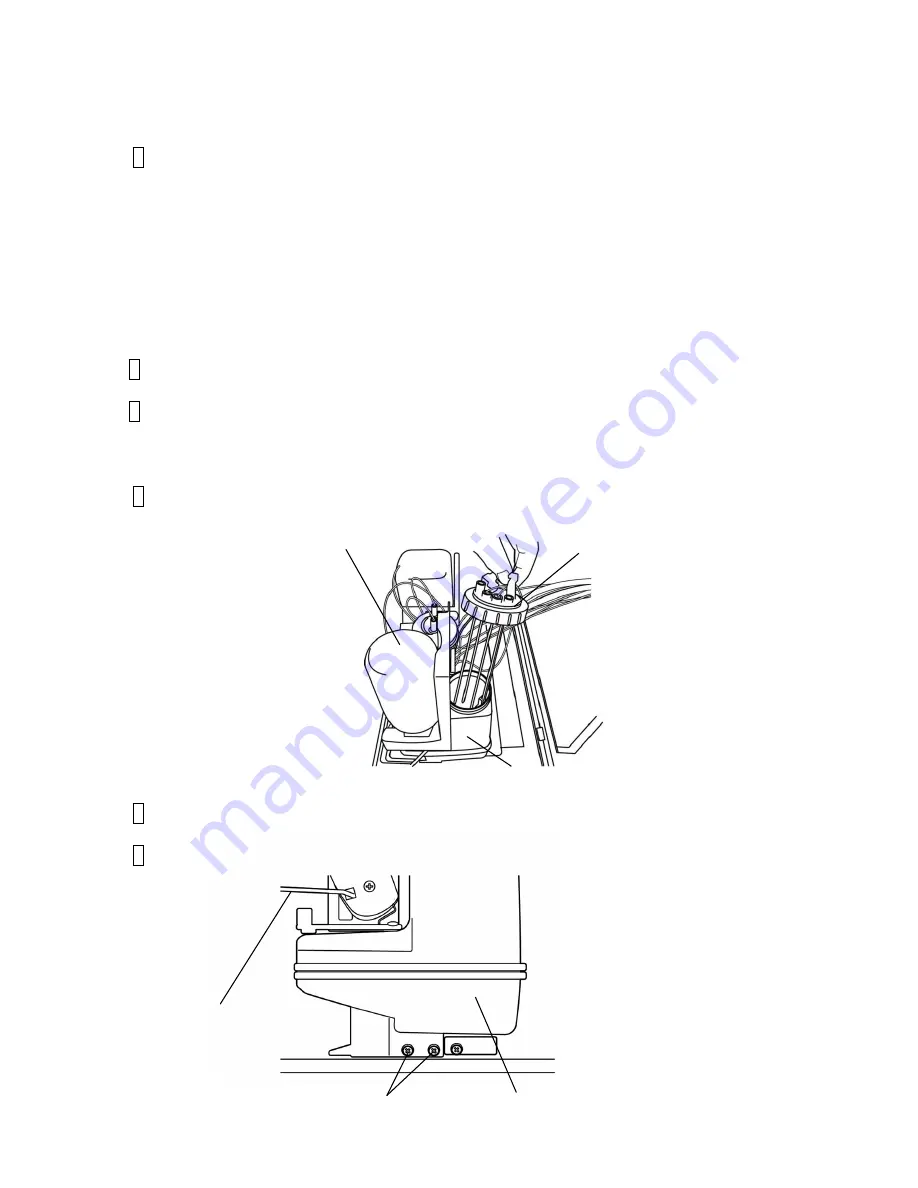
4 Remove the sensor block from the ink reservoir.
5
Remove the fixing screws (2 positions) and remove the ink reservoir.
6 Lift the lever handle and remove the ink cartridge.
Fixing screws
Ink reservoir
Lever handle
Ink reservoir
Ink cartridge
Sensor block
Summary of Contents for UX Twin Nozzle
Page 1: ...Service Manual HITACHI Printer UX Twin Nozzle Model Revision February 2017 Version A ...
Page 106: ...3 30 Circuit diagram of EZJ127A board ...
Page 123: ...3 47 Circuit diagram of EZJ129 board ...
Page 131: ...3 55 3 3 20 Electrical Connection Diagram ...
Page 151: ...4 17 7 Reset the time of the replaced solenoid to 0 on the Parts usage time management screen ...
Page 352: ...7 1 7 Attached Drawing 7 1 Circulation System Diagram Circulation System Diagram ...
Page 354: ...7 3 7 3 Electrical Connection Diagram Electrical Connection Diagram ...


