E2 - 21
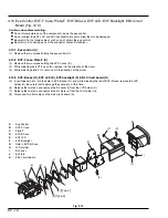
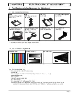
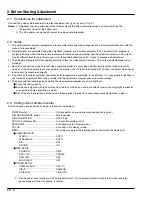
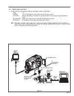
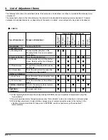
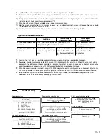
The following shows the installation positions of shields,
heat radiating rubbers, lead wires, etc. used in this video
camera/recorder.
Refer to the following and reinstall them carefully when
reassembling the product: Incomplete installation will affect
the optimum performance of product, or at worst, could
cause malfunctions.
5.1
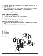
Side Case-L (Fig. 5-1)
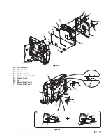
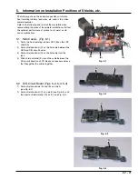
1) Paste two heat radiating rubbers CSP (B) on the LSP
shield (A).
2) Paste shield material (C) on the flat cable between the
SEN and DIG circuit boards.
3) Paste shield material (D) on the flat cable from the
lens.
4) Wind shield material (E) round the cable between the
DIG circuit board and LCD block and speaker cable so
that they gather the cables together.
5.2
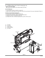
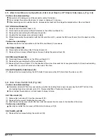
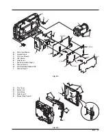
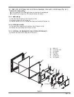
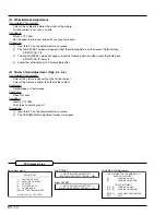
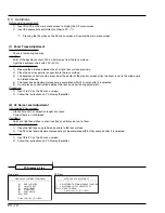
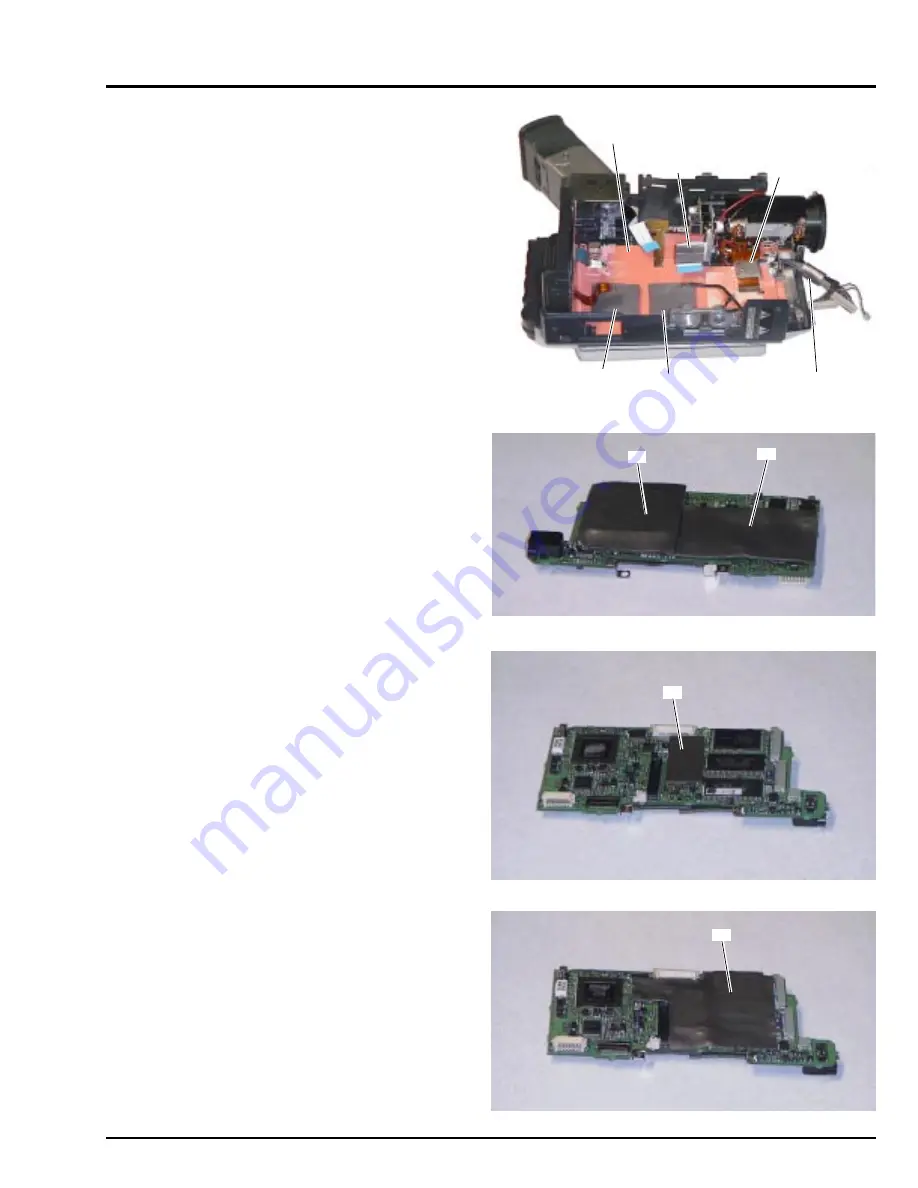
DIG Circuit Board (Figs. 5-2, 5-3, 5-4)
1) Paste shield materials (A) and (B) on side A
(see Fig. 5-2).
2) Paste shield material (C) on side B (see Fig. 5-3), and
then paste shield material (D) on (C) (see Fig. 5-4).
5.
Information on Installation Positions of Shields, etc.
Fig. 5-1
(A)
(B)
(B)
(C)
(D)
Fig. 5-2
(E)
(A)
(B)
(C)
Fig. 5-3
Fig. 5-4
(D)


