


DP-3X DIGITAL CONVERGENCE INTERFACE CIRCUIT EXPLANATION
PAGE 06-04
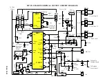
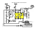
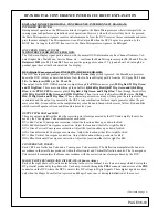
MICROPROCESSOR:
The Microprocessor is only involved in the Digital Convergence circuit related to disabling IR (Infrared Remote
Control Signals). When the DCU is put into the Digital Convergence Adjustment Mode (DCAM) or Magic Fo-
cus, the Microprocessor ignores IR pulses. This is accomplished by the
BUSY
signal from the DCU. The
BUSY
signal is routed from the DCU out the
PDG
connector pin
19
, to the
PDD1
connector pin
2
, then the
PPS1
con-
nector pin
2
to the Microprocessor
I001
pin
42
telling the Microprocessor that the DCU is busy.
RAINFOREST IC (Video Processor).
The Rainforest
I501
is only involved with the Digital Convergence circuit related to OSD and Velocity Modula-
tion inhibit during Digital convergence OSD operation in which it inhibits the Luminance from the main video.
This is accomplished by
DCU YS
from pin
19
of the
PDG
connector to
QK09
to
PPD1 PPS1
pin
2
to
Q518
to
pin
2
of
I501
.
SERVICE ONLY SWITCH:
The Service Only Switch is located just in front of the DCU on the Deflection PWB. If the front speaker grills are
removed and the front access panel is opened, the switch will be on the far left hand side. When this button is
pressed with the TV ON, the DCU enters the Digital Convergence Adjustment Mode.
If the button is pressed and held down with the TV OFF and the power button is pressed, the Digital Conver-
gence RAM is cleared. This turns off any influence from the DCU related to beam deflection. Magnetic centering
is performed in the mode as well as the ability to enter the 3X3, (9 adjustment points) mode.
NOTE
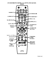
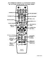
: The Digital Convergence Adjustment Mode DCAM can be entered by the Remote Control. Magic
Focus must be able to run. Press Magic Focus button on front panel, while its running, press the Magic Fo-
cus button in and hold. Stop will be displayed. Press the
INFO
button on the remote while STOP is dis-
played.
MAGIC FOCUS SWITCH:
•
Located on the Front Control panel is the Magic Focus switch. When Magic Focus is activated by the cus-
tomer pressing this switch, the DCU enters the
“MAGIC
FOCUS”
adjustment mode described earlier.
•
When the Customer presses the Magic Focus Switch, the low is sent to the Microprocessor
I001
pin
45
. The
Microprocessor pin
44
then communicates with
I010
pin
8
(Level Shift) and it outputs a low on pin
12
(Magic Sw). This low is routed through the
PPS1, PPD1
connector pin
5
to the DCU connector
PDS
pin
1
.
This starts the Magic Focus function.
•
Also the Magic Focus can be started from the Customer’s Menu by this same process.
CONVERGENCE MUTE:
IK02
is the convergence mute IC. When the +28V line collapses when power is turned off, it’s possible that the
output STKs could be damaged. To prevent this,
IK02
monitors the +28V line. If it falls too low, pin
3
will out-
put a Mute signal to pin
21
of connector
PDS
on the Digital Convergence Unit.
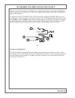
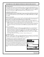
CUSTOMER’S MANUAL DIGITAL CONVERGENCE ADJUST:
This year, the Digital convergence can be adjusted by the customer.
This is accessed from the Video Menu and selecting Magic Focus. Un-
der the Magic Focus menu, select Manual. (See Figure). They have ac-
cess to the 117 adjustment points for Red and Blue. (Green is fixed as
reference). However, if after adjusting using this process, the customer
can no longer use Magic Focus. To regain Magic Focus operation, re-
turn to the Customer’s Menu-Video-Magic Focus and select AUTO.
Magic Focus will become functional however, manual adjustment data
is lost.
Move Sel Select
If you want to adjust now
START
Auto
Manual
Adjustment Mode
Aligns the Red, Green, and Blue
colors to correct for Magnet
Influences.
Magic Focus
Video
Summary of Contents for 46W500
Page 2: ...DP 3X BLANK PAGE NOTES BLANK PAGE ...
Page 6: ...DP 3X BLANK PAGE NOTES BLANK PAGE ...
Page 7: ...DP 3X CHASSIS INFORMATION POWER SUPPLY INFORMATION SECTION 1 ...
Page 8: ...DP 3X BLANK PAGE NOTES BLANK PAGE ...
Page 23: ...DP 3X CHASSIS INFORMATION MICROPROCESSOR INFORMATION SECTION 2 ...
Page 24: ...DP 3X BLANK PAGE NOTES BLANK PAGE ...
Page 35: ...DP 3X CHASSIS INFORMATION VIDEO INFORMATION SECTION 3 ...
Page 36: ...DP 3X BLANK PAGE NOTES BLANK PAGE ...
Page 50: ...DP 3X BLANK PAGE NOTES BLANK PAGE ...
Page 51: ...DP 3X CHASSIS INFORMATION AUDIO INFORMATION SECTION 4 ...
Page 52: ...DP 3X BLANK PAGE NOTES BLANK PAGE ...
Page 57: ...DP 3X CHASSIS INFORMATION DEFLECTION INFORMATION SECTION 5 ...
Page 58: ...DP 3X BLANK PAGE NOTES BLANK PAGE ...
Page 69: ...DP 3X CHASSIS INFORMATION DIGITAL CONVERGENCE INFORMATION SECTION 6 ...
Page 70: ...DP 3X BLANK PAGE NOTES BLANK PAGE ...
Page 83: ...DP 3X CHASSIS INFORMATION ADJUSTMENT INFORMATION SECTION 7 ...
Page 84: ...DP 3X BLANK PAGE NOTES BLANK PAGE ...
Page 98: ...DP 3X BLANK PAGE NOTES BLANK PAGE ...
Page 99: ...DP 3X CHASSIS INFORMATION MISCELLANEOUS INFORMATION SECTION 8 ...
Page 100: ...DP 3X BLANK PAGE NOTES BLANK PAGE ...
Page 111: ...DP 3X CHASSIS INFORMATION DP 33W 46W500 DVD PLAYER TROUBLESHOOTING SECTION 9 ...
Page 112: ...DP 3X BLANK PAGE NOTES BLANK PAGE ...
Page 131: ...DP 3X CHASSIS INFORMATION THINGS YOU SHOULD KNOW SECTION 10 ...
Page 132: ...DP 3X BLANK PAGE NOTES BLANK PAGE ...
Page 134: ...DP 3X BLANK PAGE NOTES BLANK PAGE ...
Page 161: ...DP 3X BLANK PAGE NOTES BLANK PAGE ...
Page 162: ...DP 3X BLANK PAGE NOTES BLANK PAGE ...


