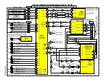


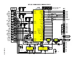

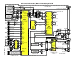

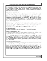
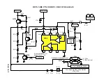

DP-3X AUDIO (Main-Terminal) CIRCUIT DIAGRAM EXPLANATION
PAGE 04-01
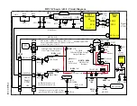
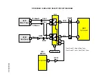
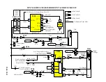
(See Audio (Main-Terminal) Signal Path Diagram for details)
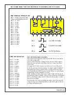
IV01 AUDIO VIDEO SELECTOR IC:
The main Audio path is delivered to the Audio/Video Selector IC
IV01
to the following pins;
62
(Left) and
64
(Right): This is the Audio input from the Main Tuner
U301
. The integrated Tuner has an Internal Audio
decoding circuit that outputs Lt (Left Total) from pin
26
and Rt (Right Total) from pin
27
. The Left continues through the
PST2
connector pin
48
and the Right continues to pin
47
. They arrive at
IV01
pins
62
and
64
respectively.
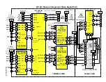
2
(DM-Left) and
4
(DM-Right): This is the Audio input from the ATSC Tuner
UD2003
. The Digital Tuner has an Internal
Audio decoding circuit that outputs Lt (Left Total) from pin
13
and Rt (Right Total) from pin
14
. The Left continues
through the
PST2
connector pin
28
and the Right continues to pin
29
. They arrive at
IV01
pins
2
and
4
respectively. The
Digital Module (ATSC Tuner) is only available on the DP-36 chassis.
59
(Left) and
61
(Right): This is the Audio input from Auxiliary 1 input. This audio is associated with component input 1
and with DVI 1 input.
29
(Left) and
31
(Right): This is the Audio input from Auxiliary 2 input. This audio is associated with component input 2
which also accepts composite video on the Y jack without a Cr plug and with DVI 2 input..
16
(Left) and
18
(Right): This is the Audio input from Auxiliary 3 input, composite or S-In only.
9
(Left) and
11
(Right): This is the Audio input from Auxiliary 4 input, composite or S-In only.
23
(Left) and
25
(Right): This is the Audio input from the front Auxiliary 5 input, composite or S-In only. These inputs
are delivered through the
PFT
connector pins
4
and
5
respectively.
SOME MODELS WITH DVD PLAYER:
If the set has a built in DVD Player, it will have
IV08
. This IC is responsible for selecting either the Front Audio from
input
5
or the DVD Player. Front Audio input
L
pin
12
and
R
Pin
2
. DVD Audio
L
pin
13
and
R
pin
1
. It outputs selected
audio
L
from pin
14
and
R
from pin
15
to
IV01
L
pin
23
and
R
pin
25
.
MONITOR OUTPUTS:
38
(Left) and
40
(Right): This is the Monitor Audio Outputs.
LEFT and RIGHT OUTPUTS:
43
(Left) and
4
5
(Right): This is the Left Total and Right Total output which represent the Audio associated with the
Main picture. The Lt and Rt represent the fact that the Audio has any Dolby ® encoding still embedded.
The outputs are then routed through the
PST2
connector pins
23
(Left) and
24
(Right) to the Center Select IC
IA51
pins
2
and
12
respectively.
IA51
is responsible for selecting the audio input from the Center Jack when the customer has set the
television to operate in TV as Center Mode. The Center audio is routed to pins
1
and
13
. The control switching signal is
provided by the Microprocessor
I001
pin
18
through the inverter
QA58
to pin
10
and
11
. A low on these pins with switch
to receive inputs from the main L and R and a high on these pins will place the IC into the Center mode.
The audio from
IA51
leaves pin
15
Left and
14
Right and into the Audio Control IC
IA01
.
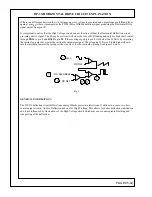
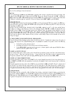
IA01 AUDIO CONTROL IC:
The NJW1160 is a sound processor includes the both BBE sound enhancement and SRS 3D Stereo.
It includes all of the functions processing audio signal for TV, such as tone control, balance, volume, mute, and AGC
functions. It also performs sound enhancement and surround. The sound enhancement regenerates high definitive and
nearly real sound, and SRS 3D Stereo regenerates 3D surround sound with two speakers.
All of the internal status and variables are controlled by I
2
C BUS interface.
The Audio is output from pin
8
(L) and
23
(R) to two different circuits. Primary route is to the Audio Output IC
IAA1
pins
2
(L) and
4
(R) and out pin
12
(L) and
7
(R) to the speaker plug
PSP
L
pin
5
and
R
pin
1
.
The Secondary route from
IA04
is to the Out to Hi-Fi jacks.
L
QA54
and
QA55
,
R QA53
and
QA52
.
(See the Audio Video Mute circuit in the Microprocessor section for details on the Mute transistors operation and con-
trol).
Summary of Contents for 46W500
Page 2: ...DP 3X BLANK PAGE NOTES BLANK PAGE ...
Page 6: ...DP 3X BLANK PAGE NOTES BLANK PAGE ...
Page 7: ...DP 3X CHASSIS INFORMATION POWER SUPPLY INFORMATION SECTION 1 ...
Page 8: ...DP 3X BLANK PAGE NOTES BLANK PAGE ...
Page 23: ...DP 3X CHASSIS INFORMATION MICROPROCESSOR INFORMATION SECTION 2 ...
Page 24: ...DP 3X BLANK PAGE NOTES BLANK PAGE ...
Page 35: ...DP 3X CHASSIS INFORMATION VIDEO INFORMATION SECTION 3 ...
Page 36: ...DP 3X BLANK PAGE NOTES BLANK PAGE ...
Page 50: ...DP 3X BLANK PAGE NOTES BLANK PAGE ...
Page 51: ...DP 3X CHASSIS INFORMATION AUDIO INFORMATION SECTION 4 ...
Page 52: ...DP 3X BLANK PAGE NOTES BLANK PAGE ...
Page 57: ...DP 3X CHASSIS INFORMATION DEFLECTION INFORMATION SECTION 5 ...
Page 58: ...DP 3X BLANK PAGE NOTES BLANK PAGE ...
Page 69: ...DP 3X CHASSIS INFORMATION DIGITAL CONVERGENCE INFORMATION SECTION 6 ...
Page 70: ...DP 3X BLANK PAGE NOTES BLANK PAGE ...
Page 83: ...DP 3X CHASSIS INFORMATION ADJUSTMENT INFORMATION SECTION 7 ...
Page 84: ...DP 3X BLANK PAGE NOTES BLANK PAGE ...
Page 98: ...DP 3X BLANK PAGE NOTES BLANK PAGE ...
Page 99: ...DP 3X CHASSIS INFORMATION MISCELLANEOUS INFORMATION SECTION 8 ...
Page 100: ...DP 3X BLANK PAGE NOTES BLANK PAGE ...
Page 111: ...DP 3X CHASSIS INFORMATION DP 33W 46W500 DVD PLAYER TROUBLESHOOTING SECTION 9 ...
Page 112: ...DP 3X BLANK PAGE NOTES BLANK PAGE ...
Page 131: ...DP 3X CHASSIS INFORMATION THINGS YOU SHOULD KNOW SECTION 10 ...
Page 132: ...DP 3X BLANK PAGE NOTES BLANK PAGE ...
Page 134: ...DP 3X BLANK PAGE NOTES BLANK PAGE ...
Page 161: ...DP 3X BLANK PAGE NOTES BLANK PAGE ...
Page 162: ...DP 3X BLANK PAGE NOTES BLANK PAGE ...


