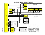
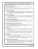

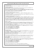

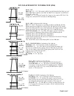

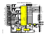


Pin 39 = FBP.
Combination of the following.
BLK
: 2.3V H-AFC: This input is received from the Horizontal Blanking (H. Blk)
signal generated in the Deflection circuit by Q706. This signal is used as a sample
pulse in the Horizontal AFC circuit, which synchronizes the Horizontal Drive signal
with the incoming Video sync signal input at pin 16. In Through Mode, pin 8.
H-AFC Fly back pulse:
5.3V ~ 9.0V Max: This input is received from the Flex
Converter and is a combination of Horizontal and Vertical blanking signals.
H Blk from the Flex Converter PFC2 Pin 7 through Q523
V Blk from the Flex Converter PFC2 Pin 6 through Q522
Used within the Rainforest for DC restoration, Pedestal level detection and Clamping
signals, such as Burst Gate Pulse.
Also, from the Mute circuit of Q528 throug D503 to force RGB mute.
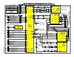
1.2 ~ 1.8V
Half Tone
H-AFC 5.3V
SCP IN Pin 49
4.2 ~ 9V
CLAMP
2.2 ~ 2.8V
Black Peak
YM/P-MUTE/BLK Pin 79
2.7 ~ 4V
P Mute
Max 9V
BLK 2.3V
0 ~ 0.5V Internal
7 ~ 9V
Blanking
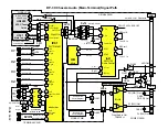
DP-3X RAINFOREST IC INFORMATION (I501)
Pin 49 = SCP.
Black Peak
: 2.2V ~ 2.8V: This input is utilized for establishing the Black Peak stop level
used in Black Peak expansion circuit. Here the Black Peak is expanded towards Black to
increase the contrast ratio.
CLAMP
: 4.2V ~ 9V: Received from the Flex Converter via connector PFC2 Pin 8. The
clamp pulse is utilized for DC restoration and blanking timing.
Pin 79 = YM/P-MUTE/BLK.
Combination of the following.
INTERNAL
: 0.0V ~ 0.5V Used internal within the Rainforest IC.
HALFTONE:
1.2V ~ 1.8V: This input is received from the Microprocessor
and is used to establish the Transparency effect of OSD. This also mutes the
video in exact timing with On Screen Display pulses (OSD). Half Tone from
the Microprocessor Pin 22 through Q415.
P MUTE
: 2.7V ~ 4V: Not Used.
BLANKING
: 7V ~ 9V: Not Used.
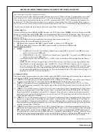
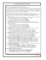
PAGE 03-07
YS3 Pin 2
1.5 ~ 9V
Analog RGB
SVM Mute
0 ~ 0.5V Internal
FBP IN Pin 39
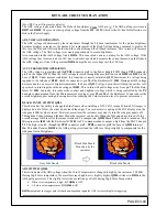
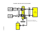
Pin 2 = YS3.
Combination of the following.
INTERNAL
: 0.0V ~ 0.5V Used internal within the Rainforest IC.
ANALOG RGB:
1.5V ~ 9V: This input is received from the Digital
Convergence Unit anytime the DCU is outputting graphics. During the
time this pulse is above 1.5V, the Velocity Modulation drive signal is
muted, so VM is turned off.
YS1 Pin 80 / YS2 Pin 1
1.1 ~ 1.7V
SVM Mute
0 ~ 0.9V Internal
Pin 80 & 1 = YS2/3.
Combination of the following.
INTERNAL
: 0.0V ~ 0.5V Used internal within the Rainforest IC.
SVM MUTE:
1.1V ~ 7V: Halftone This input is received from the
Microprocessor Pin 22. During the time this pulse is between 1.1~1.7V,
the Velocity Modulation drive signal is muted, so VM is turned off.
OSD SVM:
2.9V ~ 9V: OSD Blk, received from the Microprocessor Pin
21. This mutes the video signal in sequence with the location and timing
of the OSD Characters.
2.9 ~ 9V
OSD SVM
Mute 1
Summary of Contents for 46W500
Page 2: ...DP 3X BLANK PAGE NOTES BLANK PAGE ...
Page 6: ...DP 3X BLANK PAGE NOTES BLANK PAGE ...
Page 7: ...DP 3X CHASSIS INFORMATION POWER SUPPLY INFORMATION SECTION 1 ...
Page 8: ...DP 3X BLANK PAGE NOTES BLANK PAGE ...
Page 23: ...DP 3X CHASSIS INFORMATION MICROPROCESSOR INFORMATION SECTION 2 ...
Page 24: ...DP 3X BLANK PAGE NOTES BLANK PAGE ...
Page 35: ...DP 3X CHASSIS INFORMATION VIDEO INFORMATION SECTION 3 ...
Page 36: ...DP 3X BLANK PAGE NOTES BLANK PAGE ...
Page 50: ...DP 3X BLANK PAGE NOTES BLANK PAGE ...
Page 51: ...DP 3X CHASSIS INFORMATION AUDIO INFORMATION SECTION 4 ...
Page 52: ...DP 3X BLANK PAGE NOTES BLANK PAGE ...
Page 57: ...DP 3X CHASSIS INFORMATION DEFLECTION INFORMATION SECTION 5 ...
Page 58: ...DP 3X BLANK PAGE NOTES BLANK PAGE ...
Page 69: ...DP 3X CHASSIS INFORMATION DIGITAL CONVERGENCE INFORMATION SECTION 6 ...
Page 70: ...DP 3X BLANK PAGE NOTES BLANK PAGE ...
Page 83: ...DP 3X CHASSIS INFORMATION ADJUSTMENT INFORMATION SECTION 7 ...
Page 84: ...DP 3X BLANK PAGE NOTES BLANK PAGE ...
Page 98: ...DP 3X BLANK PAGE NOTES BLANK PAGE ...
Page 99: ...DP 3X CHASSIS INFORMATION MISCELLANEOUS INFORMATION SECTION 8 ...
Page 100: ...DP 3X BLANK PAGE NOTES BLANK PAGE ...
Page 111: ...DP 3X CHASSIS INFORMATION DP 33W 46W500 DVD PLAYER TROUBLESHOOTING SECTION 9 ...
Page 112: ...DP 3X BLANK PAGE NOTES BLANK PAGE ...
Page 131: ...DP 3X CHASSIS INFORMATION THINGS YOU SHOULD KNOW SECTION 10 ...
Page 132: ...DP 3X BLANK PAGE NOTES BLANK PAGE ...
Page 134: ...DP 3X BLANK PAGE NOTES BLANK PAGE ...
Page 161: ...DP 3X BLANK PAGE NOTES BLANK PAGE ...
Page 162: ...DP 3X BLANK PAGE NOTES BLANK PAGE ...


