


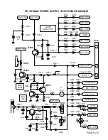
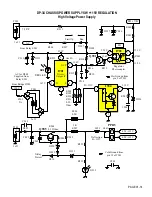


DP-3X POWER SUPPLY SHUT DOWN EXPLANATION
PAGE 01-07
The next explanation discusses the Cold Ground side shut down circuit operation.
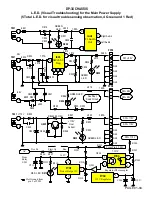
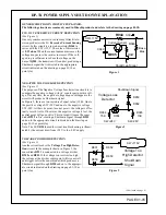
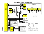
This explains the Power Supply Shut Down Circuit Diagram:
See DP-3X Power Supply Shut Down Diagram for details
Use this explanation and Diagram in conjunction with the following diagrams;
DP-3X Deflection Protect Power Supply Shut Down Circuit Diagram and
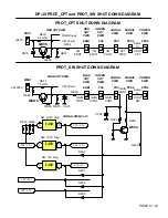
DP-3X PROT_CPT and PROT_SW Shut Down Circuit Diagram.
The Power supply is centered around the Switching Transformer
T901
and the driver IC,
I901.
This power supply creates voltages that are Switched on when the Set is turned on.
1. Audio SW +30V 2. SW +10V
3. +220V 4. SW+28V
5. SW -28V 6. SW +115V
Other supplies are generated from these 6 main voltages.
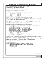
Q904 Relay Inhibit Activation. (SHUT DOWN) called COMMON ACTION CIRCUIT.
All Shut Down events will cause the main power relay to turn off. This action will stop all secondary power supplies.
The Low Voltage power supply (Stand-By) continues to operate.
If any of the
23
shut down circuits activate, the base of
Q904
will go High. This turns on
Q903
and removes the Power On
High from
PPS4
connector pin
7
called
Power_1
and the main power supply will STOP.
Q903
operates as a “latch”. This
prevents
Q904
from turning off is the shut down signal disappears after shutdown.
SOME SHUTDOWN CIRCUITS ARE DEFEATED IN STANDBY MODE. (Set Off).
When the set is turned off or in Stand By, 12 of the shut down inputs are not active.
•
Shorted
SW+35V
(from voltage divider
R940
and
R941
off the SW+115V from pin
11
of
T901
). This voltage is
monitored by
D938
.
•
Shorted
SW+10V
(from pin
16
of
T901
). This voltage is monitored by
D939
.
•
Shorted
SW+5.5V
(from pin
1
of
I905
) This voltage is monitored by
D940
.
•
Shorted
220V
(from pin
10
of
T901
) This voltage is monitored by
D941
and
D942
.
•
Shorted
SW+6.3V
(from pin
1
of
I906
) This voltage is monitored by
D943
.
•
Prot_SW
(6 shut down inputs) This voltage is monitored by
D944
.
1. SW +2.2V 2. SW +3.3V
3. SW +5V 4. SW +9V
5. SW +9.3V 6. Blue CRT VM 220V excessive current sensing circuit.
•
Shorted
SW+28V
(from pin
15
of
T901
) This voltage is monitored by
D943
.
These shut down circuits are defeated because the SW (Switched) power supplies are turned off in standby. So to prevent
faults triggering of the shutdown circuit, the sensing circuits are turned off also..
Q906
supplies the high for shutdown if any of the shut down circuit attached to its base become low.
Q906
requires emitter
voltage to operated. Emitter voltage is supplied from the
SW +6.3V
and
SW +10V
line. This voltage must be active for
Q906
to function. When the set is turned off these switched voltages disappear, so
Q906
can no longer operate.
COLD GROUND SIDE SHUT DOWN INPUTS EXPLAINED
GENERAL INFORMATION (See previous pages for generic circuit details):
All of the Power Supply Shutdown circuitry can be broken down into the following categories;
•
Voltage Missing Detection or Short Detection or Negative Voltage Loss Detection
•
Voltage Too High Detection
•
Excessive Current Detection
(Continued on page 8)
Summary of Contents for 46W500
Page 2: ...DP 3X BLANK PAGE NOTES BLANK PAGE ...
Page 6: ...DP 3X BLANK PAGE NOTES BLANK PAGE ...
Page 7: ...DP 3X CHASSIS INFORMATION POWER SUPPLY INFORMATION SECTION 1 ...
Page 8: ...DP 3X BLANK PAGE NOTES BLANK PAGE ...
Page 23: ...DP 3X CHASSIS INFORMATION MICROPROCESSOR INFORMATION SECTION 2 ...
Page 24: ...DP 3X BLANK PAGE NOTES BLANK PAGE ...
Page 35: ...DP 3X CHASSIS INFORMATION VIDEO INFORMATION SECTION 3 ...
Page 36: ...DP 3X BLANK PAGE NOTES BLANK PAGE ...
Page 50: ...DP 3X BLANK PAGE NOTES BLANK PAGE ...
Page 51: ...DP 3X CHASSIS INFORMATION AUDIO INFORMATION SECTION 4 ...
Page 52: ...DP 3X BLANK PAGE NOTES BLANK PAGE ...
Page 57: ...DP 3X CHASSIS INFORMATION DEFLECTION INFORMATION SECTION 5 ...
Page 58: ...DP 3X BLANK PAGE NOTES BLANK PAGE ...
Page 69: ...DP 3X CHASSIS INFORMATION DIGITAL CONVERGENCE INFORMATION SECTION 6 ...
Page 70: ...DP 3X BLANK PAGE NOTES BLANK PAGE ...
Page 83: ...DP 3X CHASSIS INFORMATION ADJUSTMENT INFORMATION SECTION 7 ...
Page 84: ...DP 3X BLANK PAGE NOTES BLANK PAGE ...
Page 98: ...DP 3X BLANK PAGE NOTES BLANK PAGE ...
Page 99: ...DP 3X CHASSIS INFORMATION MISCELLANEOUS INFORMATION SECTION 8 ...
Page 100: ...DP 3X BLANK PAGE NOTES BLANK PAGE ...
Page 111: ...DP 3X CHASSIS INFORMATION DP 33W 46W500 DVD PLAYER TROUBLESHOOTING SECTION 9 ...
Page 112: ...DP 3X BLANK PAGE NOTES BLANK PAGE ...
Page 131: ...DP 3X CHASSIS INFORMATION THINGS YOU SHOULD KNOW SECTION 10 ...
Page 132: ...DP 3X BLANK PAGE NOTES BLANK PAGE ...
Page 134: ...DP 3X BLANK PAGE NOTES BLANK PAGE ...
Page 161: ...DP 3X BLANK PAGE NOTES BLANK PAGE ...
Page 162: ...DP 3X BLANK PAGE NOTES BLANK PAGE ...


