


DP-3X DIGITAL CONVERGENCE INTERFACE CIRCUIT EXPLANATION
PAGE 06-03
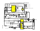
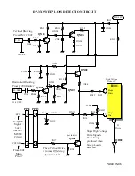
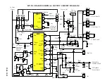
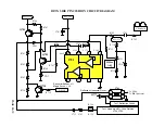
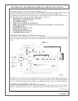
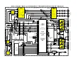
EXPLANATION OF THE DIGITAL CONVERGENCE INTERCONNECT DIAGRAM:
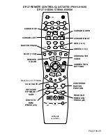
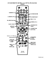
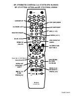
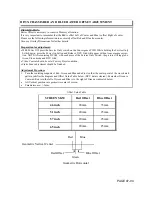
INFRARED RECEIVER:
During normal operations, the
IR
receiver directs it signal to the Main Microprocessor where it interprets the in-
coming signal and performs a predefined set of operations. However, when the Service Only Switch is pressed,
the Main Microprocessor ignores remote control commands. Now the DCU receives theses commands and inter-
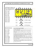
prets them accordingly. The Microprocessor is notified at pin
42
when the DCU begins its operation by the
BUSY line. As long as the BUSY line is active, the Main Microprocessor ignores the
IR
signal.
ON SCREEN DISPLAY PATH:
MICROPROCESSOR SOURCE FOR OSD:
The On Screen Display signal path is shown with the normal OSD information such as Channel Numbers, Vol-
ume Graphic Bar, Main Menu, Service Menu, etc… sent from the Main Microprocessor pins
34
,
33
and
32
to the
Rainforest
I501
pins
21
,
19
and
18
. These are positive going pulses, about 5 V p/p and about 3uS in length de-
pendant upon there actual horizontal time for display.
DCU (Digital Convergence Unit P/N CS00731) SOURCE FOR OSD:
The DCU has to produce graphics as well. When the
Service Only
switch is pressed, the Main Microprocessor
knows the DCU is Busy as described before. Now the On Screen Display path is from the DCU pins
22
,
21
and
20
to the
Rainforest
I501
pins
24
,
25
and
26
.
The output for the DCU OSD characters is output through the
PDG
connector pins (
20 Dig Red, 21 Dig Green
and 22 Dig Blue
). These are routed through their buffers (
QK06 Dig Red, QK07 Dig Green and QK08 Dig
Blue
) to the
PPD1
,
PPS1
connector pins (
1 Dig Red, 4 Dig Green and 8 Dig Blue
). Then through their buffers,
(
Q519 Dig Red, Q520 Dig Green and Q521 Dig Blue
). Then it arrives at the Rainforest
I501
at pins (
26 Dig
Red, 25 Dig Green and 24 Dig Blue
). When a character pulse arrives at any of these pins, the internal color amp
is saturated and the output is generated to the CRTs. Any combination for these inputs generates either the pri-
mary color Red, Green or Blue or the complementary color Red and Green which creates Yellow, Red and Blue
which creates Magenta or Green and Blue which creates Cyan.
OUTPUT STKs IK05 and IK04:
These are output amplifiers that take the correction waveforms generated by the DCU and amplify them to be
used by the Convergence Yoke assemblies for each color.
RV is Red Vertical Convergence correction. Adjust the location either up or down for Red.
RH is Red Horizontal Convergence correction. Adjust the location either left or right for Red.
GV is Green Vertical Convergence correction. Adjust the location either up or down for Red.
GH is Green Horizontal Convergence correction. Adjust the location either left or right for Red.
BV is Blue Vertical Convergence correction. Adjust the location either up or down for Red.
BH is Blue Horizontal Convergence correction. Adjust the location either left or right for Red.
CONVERGENCE YOKES:
Each CRT has a Deflection Yoke and a Convergence Yoke assembly. The Deflection manipulates the beam in
accordance to the waveforms produced within the Horizontal and Vertical Deflection circuits. The Convergence
Yoke assembly manipulates the Beam in accordance with the correction waveforms produced by the DCU.
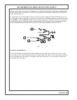
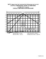
MAGIC FOCUS SENSORS AND INTERFACE: (8 Sensor Array).
Each of the eight photo cells, called solar batteries in the service manual, have their own amps which develop the
DC potential produced by the photo cells. Each amp is routed through the
PDS1
connector and arrives at the
PDS
connector on the DCU where the DCU converts this DC voltage to Digital signals. These digital signals are used
only when the Magic Focus Button is pressed and Magic Focus runs or during Initialization of the sensors.
(Continued on page 4)
Summary of Contents for 46W500
Page 2: ...DP 3X BLANK PAGE NOTES BLANK PAGE ...
Page 6: ...DP 3X BLANK PAGE NOTES BLANK PAGE ...
Page 7: ...DP 3X CHASSIS INFORMATION POWER SUPPLY INFORMATION SECTION 1 ...
Page 8: ...DP 3X BLANK PAGE NOTES BLANK PAGE ...
Page 23: ...DP 3X CHASSIS INFORMATION MICROPROCESSOR INFORMATION SECTION 2 ...
Page 24: ...DP 3X BLANK PAGE NOTES BLANK PAGE ...
Page 35: ...DP 3X CHASSIS INFORMATION VIDEO INFORMATION SECTION 3 ...
Page 36: ...DP 3X BLANK PAGE NOTES BLANK PAGE ...
Page 50: ...DP 3X BLANK PAGE NOTES BLANK PAGE ...
Page 51: ...DP 3X CHASSIS INFORMATION AUDIO INFORMATION SECTION 4 ...
Page 52: ...DP 3X BLANK PAGE NOTES BLANK PAGE ...
Page 57: ...DP 3X CHASSIS INFORMATION DEFLECTION INFORMATION SECTION 5 ...
Page 58: ...DP 3X BLANK PAGE NOTES BLANK PAGE ...
Page 69: ...DP 3X CHASSIS INFORMATION DIGITAL CONVERGENCE INFORMATION SECTION 6 ...
Page 70: ...DP 3X BLANK PAGE NOTES BLANK PAGE ...
Page 83: ...DP 3X CHASSIS INFORMATION ADJUSTMENT INFORMATION SECTION 7 ...
Page 84: ...DP 3X BLANK PAGE NOTES BLANK PAGE ...
Page 98: ...DP 3X BLANK PAGE NOTES BLANK PAGE ...
Page 99: ...DP 3X CHASSIS INFORMATION MISCELLANEOUS INFORMATION SECTION 8 ...
Page 100: ...DP 3X BLANK PAGE NOTES BLANK PAGE ...
Page 111: ...DP 3X CHASSIS INFORMATION DP 33W 46W500 DVD PLAYER TROUBLESHOOTING SECTION 9 ...
Page 112: ...DP 3X BLANK PAGE NOTES BLANK PAGE ...
Page 131: ...DP 3X CHASSIS INFORMATION THINGS YOU SHOULD KNOW SECTION 10 ...
Page 132: ...DP 3X BLANK PAGE NOTES BLANK PAGE ...
Page 134: ...DP 3X BLANK PAGE NOTES BLANK PAGE ...
Page 161: ...DP 3X BLANK PAGE NOTES BLANK PAGE ...
Page 162: ...DP 3X BLANK PAGE NOTES BLANK PAGE ...


