
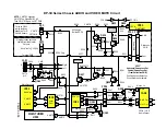
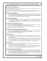
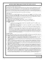
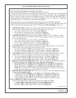

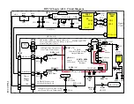


DP-3X MICROPROCESSOR NTSC SYNC INPUT CIRCUIT EXPLANATION
PAGE 02-09
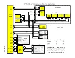
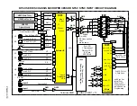
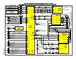
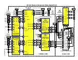
NTSC SYNC CIRCUIT DIAGRAM.
(See NTSC Sync Circuit Diagram for Details)
The Microprocessor
I001
must have Sync inputs from the Chassis to Lock it’s generation of OSD, Closed Cap-
tion, Customer’s Menu, Service Menu, etc…..
The Chassis feeds back this information in the form of Blanking pulses and Sync from the Video. The following
describes the types of feedback sync signals. The following describes the pins on the Microprocessor.
(62) H BLK (Horizontal Blanking):
•
H Blk is input to the Microprocessor at Pin
62
. H Blk is generated from the Deflection Transformer pulse
off pin
7
of
T701
, wave shaped by
Q706
. Then routed out the
PPD3
connector pin
8
to the Power Supply.
Then out the
PPS3
connector pin
8
to the Signal PWB. From here it is sent to the base of
Q025
where it
gets level shifted and inverted and into pin
62
of the Microprocessor.
(64) V BLK (Vertical Blanking):
•
V Blk is input to the Microprocessor at Pin
64
. V Blk is generated from the Vertical Output IC
I601
pin
11
. Then routed out the
PPD3
connector pin
12
to the Power Supply. Then out the
PPS3
connector pin
12
to the Signal PWB. From here it is sent to the base of
Q026
where it gets level shifted and inverted and
into pin
64
of the Microprocessor.
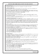
(93) MAIN AFC (Automatic Frequency Control):
•
Main AFC is input to the Microprocessor at Pin
93
. Main AFC is generated from the Main Tuner
U301
pin
16
. Then routed to
Q041
and
Q042
. Then into pin
93
of the Microprocessor.
The Microprocessor uses this input signal to align or adjust the precise Oscillator and Programmable divider
settings within the Main Tuner for proper Reception.
(92) SUB AFC (Automatic Frequency Control for PinP Tuner):
•
Sub AFC is input to the Microprocessor at Pin
92
. Sub AFC is generated from the Sub Tuner
U302
pin
16
. Then routed to
Q035
and
Q036
. Then into pin
92
of the Microprocessor.
The Microprocessor uses this input signal to align or adjust the precise Oscillator and Programmable divider
settings within the PinP Tuner for proper Reception.
(100) MAIN CCD IN:
•
The Microprocessor receives Main Sync information and strips the Closed Caption Data from line 21.
This composite sync signal is supplied to the Microprocessor from
I008
pin
14
. It uses this same input for
stripping V Chip Data.
•
When an NTSC component input is supplied to Input
2
, this is called 480i. This must also be monitored
for Closed Caption data and for V. Chip Data. If Input
2
is selected and it is 480i (NTSC), then the Micro-
processor outputs a Main CCD Select signal from pin
73
to
I008
pin
11
to select 480i input at pin
13
.
•
NOTE: Component inputs other than 480i (NTSC) are not able to display Closed Caption Data.
(97) Sub CCD IN:
•
The Microprocessor receives Sub Sync information and strips the V Chip Data. This composite sync sig-
nal is supplied to the Microprocessor from
I008
pin
15
.
•
When an NTSC component input is supplied to Input 2, this is called 480i. This must also be monitored
for V. Chip Data. If Input 2 is selected as PinP source and it is 480i (NTSC), then the Microprocessor out-
puts a Sub CCD Select signal from pin
74
to
I008
pin
10
to select 480i input at pin
1
.
(23) M/S Sync Det (Main / Sub Sync Detection):
•
The composite sync signal from either Main or PinP (Sub) is supplied to the Microprocessor from
I008
pin
4
. The Microprocessor uses the Sync signal to activate the AFC loop, and for Auto Programming.
When the channels are changed for the PinP Tuner, the Microprocessor outputs a short control signal from
pin
25
(SD Sel) to
I008
pin
9
.
I009
then outputs the Sub composite sync signal input on pin
5
. Normally
this IC outputs the Main composite sync signal input on pin
3
.
Summary of Contents for 46W500
Page 2: ...DP 3X BLANK PAGE NOTES BLANK PAGE ...
Page 6: ...DP 3X BLANK PAGE NOTES BLANK PAGE ...
Page 7: ...DP 3X CHASSIS INFORMATION POWER SUPPLY INFORMATION SECTION 1 ...
Page 8: ...DP 3X BLANK PAGE NOTES BLANK PAGE ...
Page 23: ...DP 3X CHASSIS INFORMATION MICROPROCESSOR INFORMATION SECTION 2 ...
Page 24: ...DP 3X BLANK PAGE NOTES BLANK PAGE ...
Page 35: ...DP 3X CHASSIS INFORMATION VIDEO INFORMATION SECTION 3 ...
Page 36: ...DP 3X BLANK PAGE NOTES BLANK PAGE ...
Page 50: ...DP 3X BLANK PAGE NOTES BLANK PAGE ...
Page 51: ...DP 3X CHASSIS INFORMATION AUDIO INFORMATION SECTION 4 ...
Page 52: ...DP 3X BLANK PAGE NOTES BLANK PAGE ...
Page 57: ...DP 3X CHASSIS INFORMATION DEFLECTION INFORMATION SECTION 5 ...
Page 58: ...DP 3X BLANK PAGE NOTES BLANK PAGE ...
Page 69: ...DP 3X CHASSIS INFORMATION DIGITAL CONVERGENCE INFORMATION SECTION 6 ...
Page 70: ...DP 3X BLANK PAGE NOTES BLANK PAGE ...
Page 83: ...DP 3X CHASSIS INFORMATION ADJUSTMENT INFORMATION SECTION 7 ...
Page 84: ...DP 3X BLANK PAGE NOTES BLANK PAGE ...
Page 98: ...DP 3X BLANK PAGE NOTES BLANK PAGE ...
Page 99: ...DP 3X CHASSIS INFORMATION MISCELLANEOUS INFORMATION SECTION 8 ...
Page 100: ...DP 3X BLANK PAGE NOTES BLANK PAGE ...
Page 111: ...DP 3X CHASSIS INFORMATION DP 33W 46W500 DVD PLAYER TROUBLESHOOTING SECTION 9 ...
Page 112: ...DP 3X BLANK PAGE NOTES BLANK PAGE ...
Page 131: ...DP 3X CHASSIS INFORMATION THINGS YOU SHOULD KNOW SECTION 10 ...
Page 132: ...DP 3X BLANK PAGE NOTES BLANK PAGE ...
Page 134: ...DP 3X BLANK PAGE NOTES BLANK PAGE ...
Page 161: ...DP 3X BLANK PAGE NOTES BLANK PAGE ...
Page 162: ...DP 3X BLANK PAGE NOTES BLANK PAGE ...


