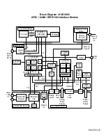

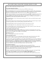

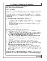
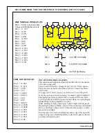
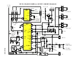

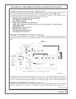
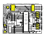

DP-3X IH01 HIGH VOLTAGE DRIVER IC WAVEFORM AND VOLTAGES
PAGE 05-04
IH01 NOT RUNNING:
Pin 1 = 12.28V
Pin 2 = 11.86V
Pin 3 = 3.96V
Pin 4 = 3.5V
Pin 5 = 1.089V
Pin 6 = 0.021V
Pin 7 = 0.0V
Pin 8 = 0.0V
Pin 9 = 0.019V
Pin 10 = 0.038V
Pin 11 = 0.038V
Pin 12 = 4.90V
Pin 13 = 0.05V
Pin 14 = 4.59V
Pin 15 = 4.96V
Pin 16 = 0.0V
Pin 1
12V P/P 33.75Khz
Pin 3
4.5V P/P 33.75Khz
Pin 4
3V P/P 33.75Khz
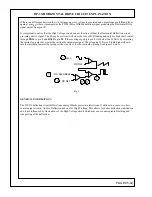
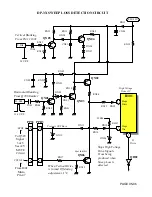
NOT RUNNING EXPLANATION:
This situation can happen and possibly lead the Service Technician
off on the wrong path.
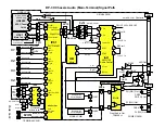
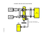
Take a quick look at the voltages for pin 3 and 14. This is the key.
These two pins tie back to the Horz. and Vert. Sweep Loss Detec-
tion Circuit.
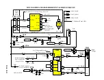
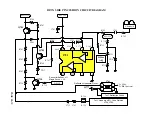
(See page 05-05 for the Sweep Loss Detection Circuit Diagram).
If the Sweep Loss circuit is activated, it outputs a high from QN02.
This high is used to shut off the CRT to prevent CRT burn, How-
ever, the Collector of QN02 is also routed to these two pins through
diodes DN09 to pin 14 and DN10 to pin 3.
When QN02 goes high, it drives pin 3 and 14 high which turns off
the internal oscillator of IH01 via pin 3. This action stops Horizontal
Drive to the High Voltage circuit. This action causes pin 1 to satu-
rate and it goes High.
Note that pin 14 is tied to an internal op-amp (-) leg. This cause the
output to stop. So no Horizontal Drive is allowed to pass to the out-
put amp. connected to pin 1.
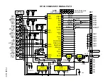
-
-
+
10
+
11
12
13
14
+
-
-
REF
15
Gnd
16
UVLO
GEN
AGC
UVP
OVP
POUT
8
7
6
5
4
3
2
1
9
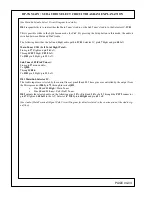
IH01 NORMAL OPERATION:
Pin 1 = 6.80V with Color Bar,
Varies with Brightness levels.
Pin 2 = 11.72V
Pin 3 = 0.59V
Pin 4 = 2.47V
Pin 5 = 1.60V
Pin 6 = 10.58V
Pin 7 = 0.0V
Pin 8 = 0.0V
Pin 9 = 4.90V
Pin 10 = 0.03V
Pin 11 = 0.03V
Pin 12 = 4.90V
Pin 13 = 0.05V
Pin 14 = 2.02V
Pin 15 = 4.96V
Pin 16 = 0.0V
Summary of Contents for 46W500
Page 2: ...DP 3X BLANK PAGE NOTES BLANK PAGE ...
Page 6: ...DP 3X BLANK PAGE NOTES BLANK PAGE ...
Page 7: ...DP 3X CHASSIS INFORMATION POWER SUPPLY INFORMATION SECTION 1 ...
Page 8: ...DP 3X BLANK PAGE NOTES BLANK PAGE ...
Page 23: ...DP 3X CHASSIS INFORMATION MICROPROCESSOR INFORMATION SECTION 2 ...
Page 24: ...DP 3X BLANK PAGE NOTES BLANK PAGE ...
Page 35: ...DP 3X CHASSIS INFORMATION VIDEO INFORMATION SECTION 3 ...
Page 36: ...DP 3X BLANK PAGE NOTES BLANK PAGE ...
Page 50: ...DP 3X BLANK PAGE NOTES BLANK PAGE ...
Page 51: ...DP 3X CHASSIS INFORMATION AUDIO INFORMATION SECTION 4 ...
Page 52: ...DP 3X BLANK PAGE NOTES BLANK PAGE ...
Page 57: ...DP 3X CHASSIS INFORMATION DEFLECTION INFORMATION SECTION 5 ...
Page 58: ...DP 3X BLANK PAGE NOTES BLANK PAGE ...
Page 69: ...DP 3X CHASSIS INFORMATION DIGITAL CONVERGENCE INFORMATION SECTION 6 ...
Page 70: ...DP 3X BLANK PAGE NOTES BLANK PAGE ...
Page 83: ...DP 3X CHASSIS INFORMATION ADJUSTMENT INFORMATION SECTION 7 ...
Page 84: ...DP 3X BLANK PAGE NOTES BLANK PAGE ...
Page 98: ...DP 3X BLANK PAGE NOTES BLANK PAGE ...
Page 99: ...DP 3X CHASSIS INFORMATION MISCELLANEOUS INFORMATION SECTION 8 ...
Page 100: ...DP 3X BLANK PAGE NOTES BLANK PAGE ...
Page 111: ...DP 3X CHASSIS INFORMATION DP 33W 46W500 DVD PLAYER TROUBLESHOOTING SECTION 9 ...
Page 112: ...DP 3X BLANK PAGE NOTES BLANK PAGE ...
Page 131: ...DP 3X CHASSIS INFORMATION THINGS YOU SHOULD KNOW SECTION 10 ...
Page 132: ...DP 3X BLANK PAGE NOTES BLANK PAGE ...
Page 134: ...DP 3X BLANK PAGE NOTES BLANK PAGE ...
Page 161: ...DP 3X BLANK PAGE NOTES BLANK PAGE ...
Page 162: ...DP 3X BLANK PAGE NOTES BLANK PAGE ...


