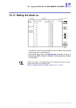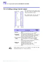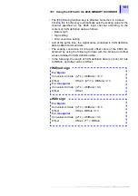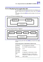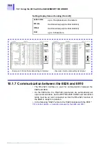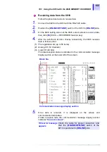
10.1 Using the 8910 with the 8826 MEMORY HiCORDER
98
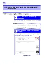
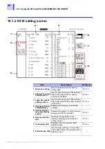
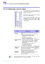
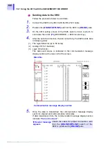
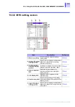
10.1.2 8910 setting screen
2. 3.
1.
4.
5.
6.
7.
8.
Item
Description
Reference
1. Block no. setting
Used to select a block for saving
setting data.
❖
2. Analog CH output
setting section
Used to set and display CAN definition
data to be output from an analog
channel of the 8910.
❖
3. Logic CH output
setting section
Used to set and display CAN definition
data to be output from a logic channel
of the 8910.
❖
4. ID trigger/ID filter
setting display
Displays the ID trigger and ID filter
settings.
-
5. Communication
message display
section
Displays the status of communication
between the 8910 and 8826.
❖
6. Screen selection
GUI
Switches display between the
interface setting screen and 8910
setting screen.
❖
7. List display GUI
Displays a list of registered CAN
definition data.
❖
8. Function key GUI
Used to make settings. The function
varies depending on the position of the
flashing cursor.
-
Summary of Contents for 8910
Page 1: ...8910 Instruction Manual CAN ADAPTER EN Aug 2018 Revised edition 7 8910A981 07 18 08H ...
Page 2: ......
Page 8: ...Contents vi ...
Page 18: ...Notes on Use 10 ...
Page 44: ...3 5 Operation Map 36 ...
Page 48: ...4 2 Program Setup 40 ...
Page 56: ...5 4 Operation Flowchart 48 ...
Page 78: ...6 6 Editing in Another Window 70 ...
Page 90: ...7 4 Setting the ID Filter 82 ...
Page 99: ...91 9 2 Setting Data Printout ...
Page 130: ...10 2 Using the 8910 with the 8841 8842 MEMORY HiCORDER 122 ...
Page 147: ......
Page 148: ......
Page 149: ......
Page 150: ......

