background image

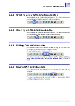
6.2  Editing the CAN Definition Data

58

6.2.9

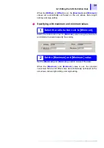
Setting the scaling

• Data can be set with a physical quantity.
• Since the output voltage from the 8910 CAN ADAPTER is

determined by the data length setting, sign setting, and D/A output
setting, the setting value entered here is not reflected in the actual
output value.

• However, this setting is useful for understanding the possible range

of physical quantity of actual data.

• When the 8910 CAN ADAPTER is used with the HIOKI 8826, 8841,

8842 MEMORY HiCORDER, the scaling setting on the 8826, 8841,
8842 MEMORY HiCORDER side can be automatically adjusted
according to the value set here.

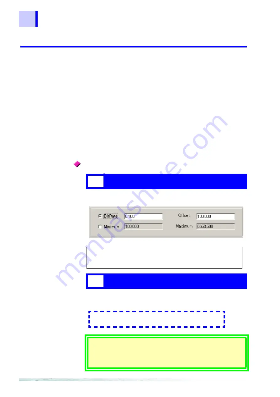
The conversion bit rate/offset value or maximum value/minimum value
can be used to specify scaling. Select one of the two methods.

Select the radio button next to [

BitRate

] when using the conversion bit

rate/offset value to specify the scaling.

Based on the physical quantity per bit of acquisition data and the offset
value, the physical quantity can be expressed by the following formula:

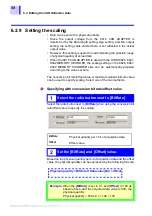
Specifying with conversion bit rate/offset value

1

Select the radio button next to [BitRate].

BitRate

Physical quantity per 1 bit of acquisition data

Offset

Offset value

2

Set the [BitRate] and [Offset] value.

Example

: When the [

BitRate

] is set to 0.1 and [

Offset

] to 100 as

shown above, and the acquired data value is 500, the
physical quantity
Physical quantity = 500 x 0.1 + 100 = 150

Physical quantity = BitRate X Data value (Bit) + Offset

Summary of Contents for 8910

Page 1: ...8910 Instruction Manual CAN ADAPTER EN Aug 2018 Revised edition 7 8910A981 07 18 08H ...

Page 2: ......

Page 3: ...nection Procedure 18 2 4 Power On Off 21 Chapter 3 Operation _________________________________ 23 3 1 Modes 23 3 2 Conversion Mode 23 3 3 Setting Mode 24 3 3 1 Activating setting mode 25 3 3 2 Contents of display in setting mode 26 3 3 3 Selecting a channel number 26 3 3 4 Selecting the CAN definition data to be output 27 3 3 5 Setting the D A conversion format logic bit position 28 3 3 6 Returnin...

Page 4: ...a new CAN definition data file 50 6 2 Editing the CAN Definition Data 52 6 2 1 Setting the message ID 53 6 2 2 Setting the data length 53 6 2 3 Setting the data start position 54 6 2 4 Setting the data pattern 55 6 2 5 Setting the sign 56 6 2 6 Setting the signal name 57 6 2 7 Setting the label name 57 6 2 8 Setting the unit 57 6 2 9 Setting the scaling 58 6 2 10 Error Massage 60 6 3 Deletion of C...

Page 5: ...the logic output allocation list 78 7 3 Massage ID Trigger 79 7 3 1 Setting the message ID trigger 79 7 3 2 Setting output channels 80 7 4 Setting the ID Filter 81 Chapter 8 Transfer of Setting Data to the 8910 ___________ 83 8 1 Setting Communication Parameters 83 8 2 Executing Data Transfer 84 8 3 In Case of Errors 85 8 4 Duplicate Bit Check 86 Chapter 9 Functions of the Setting Program ________...

Page 6: ... 3 Setting the block no 112 10 2 4 Setting analog channel output 113 10 2 5 Setting logic channel output 115 10 2 6 Displaying the registration list 116 10 2 7 Communication between the 8841 8842 and 8910 117 10 2 8 Downloading a setting data file 120 Chapter 11 Specifications_____________________________123 11 1 General Specifications 123 11 2 Specifications of Functions 125 11 3 Specifications o...

Page 7: ...Contents v Chapter 12 Maintenance and Service ___________________ 135 12 1 Service and Cleaning 135 12 2 Troubleshooting 135 ...

Page 8: ...Contents vi ...

Page 9: ...to ensure that no damage occurred during shipping In particular check the accessories panel switches and connectors If damage is evident or if it fails to operate according to the specifications contact your dealer or Hioki representative Accessories Instruction manual 1 CD R 8910 CAN set program software Japanese English 2 files for PC CAN setting function for Memory HiCorder 1 RS 232C cable D su...

Page 10: ...tive connector Approx 2 m Since this part is made to order check the specifications document and delivery date 9714 01 LOGIC CABLE one end unprocessed Approx 1 5 m 9714 02 LOGIC CABLE for Memory HiCorder Approx 1 5 m 9165 CONNECTION CORD Metal BNC Metal BNC Approx 1 5 m L9217 CONNECTION CORD Metal BNC Insulated BNC Insulated BNC for Memory HiCorder Approx 1 7 m ...

Page 11: ...f you find any damage contact your dealer or Hioki representative 9557 RS 232C CARD for Memory HiCorder Before using the instrument make sure that the insulation on the cords and cables are undamaged and that no bare conductors are improperly exposed Using the product in such conditions could cause an electric shock so contact your dealer or Hioki representative for repair ...

Page 12: ...cautions in the manual before use We disclaim any responsibility for accidents or injuries not resulting directly from instrument defects In the manual the symbol indicates particularly important information that the user should read before using the instrument Indicates AC Alternating Current Indicates DC Direct Current Indicates the OFF side of the power switch Indicates the ON side of the power...

Page 13: ...he screen and the keys are indicated in brackets Click Press and quickly release the left button of the mouse Right click Press and quickly release the right button of the mouse Double click Quickly click the left button of the mouse twice Drag While holding down the left button of the mouse move the mouse and then release the left button to deposit the chosen item in the desired position Activate...

Page 14: ...Primary electrical circuits of heavy equipment fixed installations connected directly to the distribution panel and feeders from the distribution panel to outlets CAT IV The circuit from the service drop to the service entrance and to the power meter and primary overcurrent protection device distribution panel Using a measurement instrument in an environment designated with a higher numbered categ...

Page 15: ...ge the equipment To avoid such hazards we recommend observing the following precautions for power connections 1 When powering the 8910 from the supplied AC adapter before connecting devices to the 8910 plug the supplied grounded power cord of the AC adapter into the same outlet as that used to power the devices to be connected 2 2 1 Connecting the AC adapter Page 16 and 2 3 Connection Procedure Pa...

Page 16: ...or the CD R Always hold the disc by the edges so as not to make fingerprints on the disc or scratch the printing Never touch the recorded side of the disc Do not place the disc directly on anything hard Do not wet the disc with volatile alcohol or water as there is a possibility of the label printing disappearing To write on the disc label surface use a spirit based felt pen Do not use a ball poin...

Page 17: ...e cable is not exposed If a color inside the cable is exposed do not use the cable Carefully read and observe all precautions in this manual Using an connection cord other than that specified by HIOKI may damage the BNC connector or result in measurement errors due to contact failure Even when using the 8910 within the permitted operating temperature 10 to 55 C and humidity ranges display on the L...

Page 18: ...Notes on Use 10 ...

Page 19: ...type of data to be acquired is set by using a PC with settings transferred and saved in internal memory of the 8910 via the RS 232C Internal memory can store up to 50 items of CAN definition data Since you can change allocated output channels by using the LCD and operation keys on the front panel the instrument can be used in various applications without a PC Product Overview Chapter 1 1 1 Overvie...

Page 20: ...5 kbps 250 kbps 500 kbps and 1 Mbps 5 Detailed settings using a PC Easy to use PC application software enables the detailed settings of data to be acquired from a CAN bus 6 Observation with your existing recorder The output signal level ranges from 5 to 5 V and the value is held until subsequent signal output Therefore output from the 8910 can be connected to an ordinary recorder Thus you can obse...

Page 21: ...put Online LED This LED indicates whether the 8910 and PC can communicate via the RS 232C The LED goes on in green when the ONLINE OFFLINE switch is set to the ONLINE side for enabling communication The LED goes on in orange when the 8910 is engaged in communication ESC escape key Key used for various settings SEL select key Key used for various settings ENT enter key Key used for various settings...

Page 22: ...N2 are independent two different networks can be connected These ports can also be used to supply power to the 8910 Power Switch This switch turns the power ON and OFF The switch is effective for power supplied through DCIN CAN1 and CAN2 AC adapter connection Terminal This terminal is used to connect the AC ADAPTER A DC power supply 10 to 30 V can also be connected ONLINE OFFLINE Switch This switc...

Page 23: ...following locations Subject to direct sunlight Subject to high levels of dust steam or corrosive gases Avoid using the equipment in an environment containing corrosive gases e g H2S SO2 NI2 and CI2 or substances that generate harmful gasses e g organic silicones cyanides and formalins Subject to vibrations In the vicinity of equipment generating strong electromagnetic fields Preparation Chapter 2 ...

Page 24: ...o 240 VAC with 10 stability at 50 60 Hz To avoid electrical hazards and damage to the instrument do not apply voltage outside of this range To avoid electrical accidents and to maintain the safety specifications of this instrument connect the power cord only to a 3 contact two conductor ground outlet 1 Connect the AC adapter to the 8910 2 Connect the AC adapter plug to an outlet ...

Page 25: ...AC adapter any of the following power sources can be used DC power supply 10 to 30 V Voltage fluctuations of 10 from the rated supply voltage are taken into account Power supplied from CAN input port 10 to 30 V Voltage fluctuations of 10 from the rated supply voltage are taken into account ...

Page 26: ...onductors of connecting cables connect in common to the Model 8910 chassis ground they are not isolated Therefore supplying power from different sources to the instrument and a connecting device could cause electric shock and equipment damage To avoid these hazards power should always be supplied from the same source Even when power is supplied from the same source as a result of wiring potential ...

Page 27: ...atives regarding common ground connection methods a Connect the grounds of devices running on DC power to the AC adapter s ground b Connect pin 3 CAN_GND of the 9713 01 CAN Cable to the ground of the device to be connected Note In method b above because of wire length and CAN cable wiring conditions some potential difference may remain between grounding points so we recommend a as the preferred me...

Page 28: ...uding response bits to the CAN bus Therefore when only one device connected to the bus in addition to the 8910 communication is not possible since response bits cannot be exchanged Therefore be sure to connect the bus to which the 8910 is connected with two or more devices to enable communication Connection Points The 9714 01 or 9714 02 LOGIC CABLE This is the 9714 02 The 9165 or L9217 CONNECTION ...

Page 29: ...ge will flash on the display 2 4 Power On Off Check the following points before the power switch is turned on When using the AC adapter make sure that the power supply complies with the rated voltage 100 240 VAC and rated frequency 50 60 Hz of the 8910 The instrument is correctly connected Section 2 1 15p 1 Connect the cables and cords 2 Turn on the power 3 The 8910 then begins internal initializa...

Page 30: ...ff 22 The error message continues flashing until a key is pressed While the error message is displayed RS communication is disabled To conduct RS communication press any key to place the instrument in conversion mode ...

Page 31: ...eady begun to receive signal input from CAN1 or CAN2 at this point When the CAN message assigned to the output channel enters the CAN port the CAN LED goes on in green Operation Chapter 3 3 1 Modes Conversion mode This mode converts the CAN signal input from the CAN 1 or 2 port according to the set definition data and outputs the converted signal from the specified analog or logic output terminal ...

Page 32: ...he 12 analog output channels or six 24 bits logic output channels for output 3 3 Setting Mode CAN definition data must be set in advance using the PC application Chapter 6 49p The keys on the 8910 enable the following settings Channel selection Label selection D A conversion format logic bit position But the setting bellow cannot be made solely by using the 8910 CAN input port selection ID trigger...

Page 33: ...EL key changes the mode in the following sequence In setting mode pressing the ENT key displays the following indication The instrument is now in setting mode OFF appears when the channel is not assigned with data for output 1 Position the ONLINE OFFLINE switch to the OFFLINE side 2 Press the SEL key 3 In setting mode press the ENT key CONV MODE CAL MODE SET MODE SEL key SEL key SEL key Conversion...

Page 34: ...hannel 1 to 12 After analog channel 12 logic channels are shown in order of A0 to F3 then the indication returns to analog channel 1 Hold down the SEL key until the desired channel is shown After selecting a channel press the ENT key This enters the new setting Example of display for analog channel Analog 01 labelname M Logic A0 labelname 0 Example of display for logic channel 1 Activating setting...

Page 35: ...ition pressing the SEL key changes the indication of the label name Hold down the SEL key until the label name of definition data to be output is shown After selecting the CAN definition data to be output press the ENT key This enters the setting 1 Enter the channel number Section 3 3 3 26p 2 Press the SEL key and select a label name 3 Press the ENT key To disable output use the SEL key to select ...

Page 36: ...ts flashing again 1 Enter the CAN definition data Section 3 3 4 27p 2 Press the SEL key and set the value 3 Press the ENT key CAN data conversion and output are stopped for all channels while the D A conversion format logic bit position is being set D A conversion format This format is used to select analog signal output in a range from 5 to 5 V or 0 to 5 V Selecting Bipolar B sets the output rang...

Page 37: ...o conversion mode Bipolar Monopolar 0 0V 5 0V 32767 32768 65535 0 0 32768 0 0 32767 32767 5 0V 2 5V 0 0V 32767 65535 2 16 1 2 1 16 2 1 16 2 1 16 1 2 16 1 2 1 16 1 2 1 16 1 2 1 16 1 5 0V Relationship between input data and output voltage With sign Without sign With sign Without sign Bit position When the assigned CAN definition data is 2 bits or more this setting determines the type of bit data tha...

Page 38: ...sition the ONLINE OFFLINE switch to the OFFLINE side Make sure that the ONLINE LED is off When the instrument is in calibration mode pressing the SEL key changes the mode in the following sequence In calibration mode pressing the ENT key displays the following indication 3 4 Calibration Mode 1 Position the ONLINE OFFLINE switch to the OFF LINE side 2 Press the SEL key 3 In calibration mode press t...

Page 39: ...l After selecting a channel press the CAL key to output a calibration signal The calibration signal is output from the selected channel only while the CAL key is held down CAN data conversion and output are stopped for all channels during calibration signal output For an analog channel the output alternates between 0 V and 5 V at 100 ms intervals For a logic channel the output bit pattern alternat...

Page 40: ...tion Mode 32 3 4 4 Returning to conversion mode Press the ESC key to exit from calibration mode and return to conversion mode When no key entry is made for about 30 seconds the 8910 also returns to conversion mode ...

Page 41: ... 下図の表示となるように SEL キーで選択し ENT キーにて決定することでチャネル出力OFFとなります indicates a flashing display Conversion Mode Calibration Mode Setting Mode Output OFF setting When label change is possible in setting mode use the SEL key to display the indication below then press the ENT key This turns off channel output While pressing the ESC key SEL key and ENT key simultaneously turn on the power switch of the 8910 Press ...

Page 42: ...de RS communication is enabled The keys are not operable in this mode key lock In OFFLINE mode the 8910 accepts operations RS communication is not possible in this mode Even when the instrument is in ONLINE mode the ONLINE LED goes off and RS communication is disabled in the following cases Keys are not operable when the instrument is in ONLINE mode key lock Even in ONLINE mode key lock pressing a...

Page 43: ...The entered setting is written to backup memory immediately before CAN conversion and output In setting mode CAN conversion and output are conducted when setting item selection returns to the channel selection Therefore the setting is written to backup memory at this time If 8910 power is turned off before setting item selection returns to the channel selection the setting change made in setting m...

Page 44: ...3 5 Operation Map 36 ...

Page 45: ...TER In this mode up to 50 items of CAN definition data to be registered in the 8910 can be selected with data to be output from the 8910 output channel selected from the data registered After setting is completed the setting data is transferred to the 8910 via the RS 232C This mode is used to create or edit a CAN definition data file Preparation of the CAN Set Program Chapter 4 4 1 Overview 8910 s...

Page 46: ...Setup Personal computer IBM PC AT compatible Pentium 133 MHz or higher recommended Min 64 MB RAM recommended Free hard disk space 5 MB RS 232C capability CD ROM drive to install software OS Microsoft Windows 95 OSR2 or later Windows 98 Windows NT4 0 SP3 or later Windows Me Windows 2000 Windows XP Assuming that your CD ROM drive is drive R 1 Click the Start button 2 Select Run on the Windows Start ...

Page 47: ...s asking about file deletion select Yes Method 2 1 Click the Start button to open the Windows Start Menu 2 Select Settings Control Panel 3 Click the Add Remove Programs icon to open the Add Remove Programs Properties dialog box 4 Select 8910 CanSet Program in the list shown in the Add Remove Programs Properties dialog box then click the Add Remove The uninstaller starts up and deletes the program ...

Page 48: ...4 2 Program Setup 40 ...

Page 49: ... PC to the 8910 1 Turn off the power of the 8910 2 Make sure that no cable is connected to the CAN1 or CAN2 port of the 8910 3 Connect the RS cable to the RS 232C terminal on the 8910 4 Connect the other end of the RS cable to the RS 232C terminal on the PC 5 Turn on the power of the 8910 6 Position the ONLINE OFFLINE switch to ONLINE side Starting the CAN Set Program Chapter 5 5 1 Connecting the ...

Page 50: ... starts up and the following 8910 setting window appears on the display To end the program Select Close or Exit on the File pull down menu Selecting Close only closes the 8910 setting window Selecting Exit closes the 8910 setting window and CAN definition data editing window Section 6 6 65p at the same time 5 2 Starting Up the Condition Setting Program 2 3 8 9 10 11 13 1 4 5 6 7 14 12 ...

Page 51: ...data input 6 CAN definition data list detail display Checking this item displays all setting items of definition data in list format When this setting is off only the necessary items are displayed 7 CAN definition data list This section displays the content of the downloaded CAN definition data file In the initial state the content of the previously used file is displayed 8 ID filter setting Each ...

Page 52: ...5 2 Starting Up the Condition Setting Program 44 14 Status bar This section indicates the current status Checking Status bar on the View pull down menu displays the status bar ...

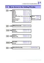
Page 53: ...n 7 1 1 71p Section 5 2 42p Section 9 1 2 88p Section 9 1 1 87p Section 9 2 1 89p Section 9 2 2 89p Section 9 2 3 90p Section 5 2 42p New Open Section 6 6 2 69p Section 6 6 3 69p Modify Password Section 9 4 93p Send Settings Section 8 2 84p Section 8 1 83p Toolbar Status bar Section 5 2 42p Section 5 2 42p Cascade Tailed Section 9 3 92p Section 9 3 92p About 8910 Can Set Section 9 5 94p ...

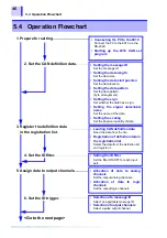
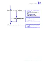
Page 54: ...name of the data Setting the scaling Set the physical quantity of data 3 Register the definition data in the registration list 4 Set the ID filter Loading CAN definition data Read the data from the file Registration of definition data in the registration list Select the data from the definition list and register it Setting the ID filter Set the filter ON OFF for each input port 5 Assign data to ou...

Page 55: ...s Set the communication parameters on the PC Transmission of data Transfer the data to the 8910 8 Record the setting data Storage of set data Save the set data Printing of set data Print the setting data 9 End the setting procedure Ending the 8910 CAN set program Close the application software ...

Page 56: ...5 4 Operation Flowchart 48 ...

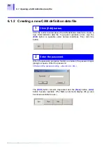
Page 57: ... 1 Opening a CAN definition data file The stored CAN definition data file can be read Click the button located to the right of the CAN definition data file name box to show the file loading dialog box From the list of CAN definition data files shown in the file loading dialog box select a file with extension cdf to read Clicking the Start button on the dialog box updates the CAN definition data li...

Page 58: ...s only the Edit button is operable under normal conditions First click this button When the password protection function is enabled the password input dialog box opens Enter the password Details of the password setting Section 9 4 93p The Edit button remains depressed and the New button Add button become operable The Memo comment display 66 p also becomes available for use 1 Click Edit button 2 En...

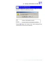
Page 59: ...g box that asks whether to initialize the CAN definition data file Clicking OK deletes the content of the currently displayed CAN definition data list and executes initialization 3 Click the New button OK Creates a CAN definition data file Cancel Cancels creation of a CAN definition data file ...

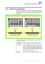
Page 60: ... definition data setting window This window is used to set items such as the message ID and start bit 6 2 Editing the CAN Definition Data 1 Click the Add button 2 Set items CAN definition data setting window Setting of message ID Setting of data start position Setting of data length Setting of data type Setting of sign Setting of signal name Setting of label name Setting of unit Setting of scaling...

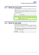
Page 61: ...gth Enter the size bits of data to be acquired Since the maximum size of data that can be captured by the 8910 is 2 bytes 16 bits a value from 1 to 16 can be entered in the input box The data length set here together with the data start position and data pattern system settings determines the location of acquisition data in the CAN data frame ID 0 to 1FFFFFFF Example When 64 is entered in the inpu...

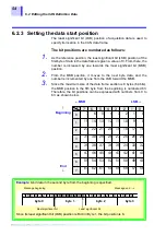
Page 62: ...ince the maximum size of the data frame section is 8 bytes 64 bits the MSB position in the 8th byte from the beginning is numbered 63 Therefore the bit positions can be expressed with numbers from 0 to 63 as shown below 7 6 5 4 3 2 1 0 15 14 13 12 11 10 9 8 7 6 5 4 23 22 21 20 19 18 17 16 31 30 29 28 27 26 25 24 39 38 37 36 35 34 33 32 47 46 45 44 43 42 41 40 55 54 53 52 51 50 49 48 63 62 61 60 59...

Page 63: ...3 22 21 20 19 18 17 16 2 31 30 29 28 27 26 25 24 3 7 6 5 4 3 2 1 0 15 14 13 12 11 10 9 8 bit byte 7 6 5 4 3 2 1 0 0 1 23 22 21 20 19 18 17 16 2 31 30 29 28 27 26 25 24 3 23 22 21 20 19 18 17 16 9 8 23 22 21 20 19 18 17 16 25 24 MSB LSB MSB LSB The position of Bit 9 is the MSB most significant bit position The position of Bit 25 is the MSB most significant bit position U L Motorola Data is extracte...

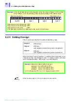
Page 64: ... based on U L Motorola FF00 Value based on L U Motorola 00FF Value based on L U Intel 00FF The data start position is 8 in Motorola format and 0 in Intel format 7 6 5 4 3 2 1 0 7 6 5 4 3 2 1 0 7 6 5 4 3 2 1 0 7 6 5 4 byte 0 byte 1 byte 2 byte 3 Data frame beginning Data frame end Unsigned Without sign 1 Signed With sign with negative number being one s complement 2 Signed With sign with negative n...

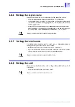
Page 65: ...d to the 8826 8841 8842 MEMORY HiCORDER as comment data 6 2 7 Setting the label name The label name must be set for each item of data since data is distinguished by the label name on the 8910 Make sure that the same label name is not used twice Up to 16 characters can be used in the label name To enter a label name click the label name input box then enter a name 6 2 8 Setting the unit Data can be...

Page 66: ... set here The conversion bit rate offset value or maximum value minimum value can be used to specify scaling Select one of the two methods Select the radio button next to BitRate when using the conversion bit rate offset value to specify the scaling Based on the physical quantity per bit of acquisition data and the offset value the physical quantity can be expressed by the following formula Specif...

Page 67: ...nimum when using the maximum and minimum values to specify the scaling Set the Maximum and Minimum possible values of the data When the Maximum and Minimum value is set the physical conversion bit rate and offset value are automatically set based on the set values data length setting and sign setting Specifying with maximum and minimum values 1 Select the radio button next to Minimum 2 Set the Max...

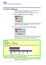
Page 68: ... CAN data frame but current settings deviate from the range of the CAN data frame Confirm that the data length data start position and data pattern settings do not cause any conflict If error message Input please appears If error message Bad Can define data appears Example Data Length 10 bits Data start position 0 Bit 0 in Byte 0 Data pattern U L Motorola When the settings above are entered the tw...

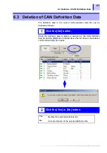
Page 69: ...nition data to delete is selected in the CAN definition data list and the Del button located above the list clicked the deletion confirmation dialog box opens 6 3 Deletion of CAN Definition Data 1 Click the Del button 2 Click the Yes or No button Yes Deletes the selected definition file No Cancels deletion of the selected definition file ...

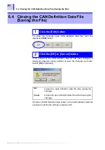
Page 70: ... asking whether to save the changes you made Select OK or Cancel All items of CAN definition data shown in the CAN definition data list are saved and the file will have extension cdf 6 4 Closing the CAN Definition Data File Saving the File 1 Click the Edit button 2 Click the OK or Cancel button OK Closes the open definition data file after saving the changes Cancel Closes the open definition data ...

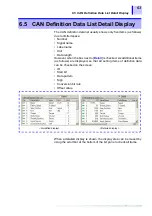
Page 71: ...etail is checked six additional items as follows are displayed so that all setting items of definition data can be checked on the screen ID Start bit Data pattern Sign Conversion bit rate Offset value When a detailed display is shown the display area can be moved by using the scroll bar at the bottom of the list pane to check all items 6 5 CAN Definition Data List Detail Display Simplified display...

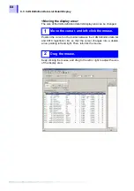
Page 72: ...ition the cursor on the border between the CAN definition data list and 8910 registration list so that the cursor changes into a double arrow pointing left and right Then left click the mouse Keep clicking the mouse and drag to the left or right to adjust the size of the display area 1 Move the cursor and left click the mouse 2 Drag the mouse ...

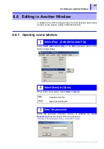
Page 73: ...ile on the File pull down menu in the 8910 setting window When a new menu opens select New or Open When the password protection function is enabled the Input Password dialog box opens Enter the password Details of the password setting Section 9 4 93p 6 6 Editing in Another Window 1 Select File CAN Define Data File 2 Select New or Open New Creates a new file Open Opens an existing file 3 Enter the ...

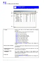
Page 74: ...he currently open file Save as for the currently open file Checking Toolbar on the View pull down menu displays the toolbar 2 Memo comment display A comment regarding the CAN definition data file can be entered and displayed 3 Number of registered data items display The number of CAN definition data items registered in the CAN definition data file is displayed 4 CAN definition data list display Th...

Page 75: ... End Select Close or Exit on the File pull down menu Selecting Close only closes the CAN definition data editing window Selecting Exit closes the CAN definition data editing window and 8910 setting window Section 5 2 42p at the same time ...

Page 76: ...xit Section 6 6 2 69p Section 6 6 3 69p Section 6 6 1 65p Section 6 6 5 69p Section 6 6 5 69p Cannot be used in CAN definition data editing mode Section 9 2 3 90p Section 6 6 1 65p Modify Password Section 9 4 93p Toolbar Status bar Section 6 6 1 65p Section 6 6 1 65p Cascade Tailed Section 9 3 92p Section 9 3 92p About 8910 Can Set Section 9 5 94p ...

Page 77: ...ion data file 6 6 4 Editing CAN definition data The definition data can be edited by double clicking an item on the list by using the pull down menu or using the toolbar How to edit the data Section 6 2 52p The three icons above on the toolbar are used for editing Add new data Edit selected data and Delete selected data from left to right 6 6 5 Saving CAN definition data The pull down menu or tool...

Page 78: ...6 6 Editing in Another Window 70 ...

Page 79: ...n be registered on the 8910 7 1 1 Opening a registration list Select Open on the File pull down menu or click the icon on the toolbar to download a stored 8910 setting file From the 8910 setting files displayed in the file read dialog box select the desired file with extension cmu Executing the file read command updates the 8910 registration list and analog logic output allocation list Settings Ch...

Page 80: ...ializes the contents of the 8910 registration list and analog logic output allocation list When the registered contents already exist a confirmation dialog box appears prior to deletion Clicking the New button located above the 8910 registration list produces the same result Click the button located to the right of the CAN definition data file name box to show the file loading dialog box From the ...

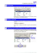
Page 81: ...y The CAN port setting section is located above the CAN definition data list pane Select CAN1 or CAN2 port of the 8910 to input the selected definition data The highlighted line in the CAN definition list can be added to the 8910 registration list by dragging and dropping or by clicking the Add button above the 8910 registration list 3 Selecting data 4 Selecting a CAN port 5 Registering from the C...

Page 82: ...mory of the 8910 7 1 3 Deleting data from the registration list Clicking an item on the 8910 registration list highlights the line selected When there is a highlighted line in the 8910 registration list the Del button located above the 8910 registration list becomes operable Clicking this button deletes the item selected OK Overwrites existing data and registers new data in the list Cancel Stops t...

Page 83: ...o output that data Selecting and clicking an item in the 8910 registration list highlights the line selected When the highlighted line is dragged and dropped onto a channel section in the analog output allocation list it is assigned to that output channel 7 2 Allocation to Output Channels 1 Select and click an item on the registration list 2 Drag and drop the item on to a channel section Register ...

Page 84: ...tem to be deleted from the analog output allocation list is right clicked A dialog box appears asking whether to delete the data Click Yes to delete the selected line 3 Select B or M B Bipolar Analog signal is output in 5 V range M Monopolar Analog signal is output in 0 to 5 V range Double clicking a registered channel can also set the D A conversion format Therefore the type of D A conversion can...

Page 85: ...to the following channel Example 1 Data with label name abc and a data length of 5 bits assigned to Bit 1 in Ch A is allocated as shown below In this example if another signal is already allocated to 3 bits from Bit 2 to Bit 0 in Ch B the original signal only remains in Bit 0 in Ch B because overlapping bits are overwritten in one bit units Example 2 Dragging and dropping data with a data length o...

Page 86: ...an item to be deleted from the logic output allocation list is right clicked A dialog box appears asking whether to delete the data Click Yes to delete the selected line For logic output channel deletion data can only be specified by line bit 1 Select an item to be deleted and right click 2 Click Yes ...

Page 87: ...n the M_ID input box 7 3 Massage ID Trigger Analog logic output is held until the next CAN message is converted Therefore setting the ID trigger does not allow you to observe the output pulse even when a logic output is held H In such case turn off the power of the 8910 then turn it back on and set the logic output to L before setting the ID trigger 1 Check the ID_TRIGGER box 2 Input the massage I...

Page 88: ...el name column indicates the message ID set as a trigger The Bit will be fixed at 1 1 Double click a logic channel When a channel already assigned with output data is specified that channel outputs both the assigned data and ID trigger simultaneously When reliable detection of the ID trigger is important select a channel without output data assigned When the ID filter is enabled the ID set with th...

Page 89: ...nnels The filter results in the acquisition of standard format or extended format only The filter can improve acquisition performance 7 4 Setting the ID Filter STD ID filter allows the acquisition of standard format only EXT ID filter allows the acquisition of extended format only NON ID filter is disabled and both standard and extended formats can be acquired ...

Page 90: ...7 4 Setting the ID Filter 82 ...

Page 91: ...he 8910 Select Settings on the Comm pull down menu The Comm Condition dialog box is opened Make the following RS 232C settings Baud Rate to 19 2 k Data Bits to 8 Parity to None Stop Bits to 1 For Port select the RS port used on the PC side Transfer of Setting Data to the 8910 Chapter 8 8 1 Setting Communication Parameters 1 Select Comm Settings 2 Make the RS 232C settings ...

Page 92: ...e 3 Set the 8910 to ONLINE mode Position the online offline switch to ONLINE side 4 Execute transfer by selecting Send on the Comm pull down menu 5 A progress bar appears during write operation to indicate the status of writing 6 When transfer operation is completed a dialog box appears for reporting that the conditions have been set 8 2 Executing Data Transfer ...

Page 93: ...tes that the 8910 was found but communication operation failed Is the ONLINE OFFLINE switch positioned to ONLINE side Indicates that the message ID trigger setting is incomplete If the message ID trigger setting is turned ON with the ID_TRIGGER check box selected Is a trigger ID set ID no in M_ID input box Is a logic channel set for signal output If an error occurs the 8910 may remain in Remote mo...

Page 94: ...rring setting data If duplicate bits are found the following items are displayed Registration list item no Massage ID Signal name of the duplicate data The transfer operation can be resumed or cancelled 8 4 Duplicate Bit Check OK Transfer data to the 8910 Cancel Cancels data transfer to the 8910 ...

Page 95: ...con below on the toolbar The file save dialog box is shown 2 Enter a file name in the file save dialog box 3 Click the OK button 4 The 8910 registration list and analog digital output allocation list are saved as an 8910 setting file with the specified name The file contains List items registered in 8910 registration list up to 50 items Analog output channel allocation settings 12 channels Logic o...

Page 96: ...he File pull down menu or clicking the icon below on the toolbar If the current list has no file name such as for a newly created file executing the Save command prompts the Save as command Executing the Save command overwrites an existing file with the current list content Careless use of this command may result in the loss of current list data ...

Page 97: ...e label name unit data length Analog channel settings i e channel no signal name label name unit D A Logic channel settings i e channel no bit signal name label name assigned bit Actual printouts Section 9 2 4 90p 9 2 2 Print preview Prior to printing the print image can be displayed on the screen by selecting Print Preview on the File pull down menu 9 2 Setting Data Printout HIOKI 8910 YYY MM DD ...

Page 98: ...9 2 Setting Data Printout 90 9 2 3 Setting the printer Select Printer Setup on the File pull down menu to set printer conditions 9 2 4 Examples of printouts ...

Page 99: ...91 9 2 Setting Data Printout ...

Page 100: ...ion data setting window is opened it appears on top of the 8910 setting window Both windows can be repositioned for easy viewing by selecting Cascade or Tiled on the Window pull down menu 9 3 Displaying Windows Cascade arrangement Tiled arrangement ...

Page 101: ... must consist of only alphanumeric characters After this setting is entered the password must be entered to open a CAN definition data file To disable the password protection function Deselect the check box There will be no need to enter the password to open a CAN definition data file after entering the setting The password protection function is disabled in default installation status with no pas...

Page 102: ...on Check 94 You will be asked to provide the software version no when making an inquiry regarding the product To check the software version select About 8910 Can Set on the Help pull down menu 9 5 Version Check ...

Page 103: ... channel setting Display the setting data list Automatically set the scaling of the Memory HiCorder according to scaling information in the CAN definition data Supported models and versions Connection to Memory HiCorder Chapter 10 Memory HiCorder 8826 Ver 2 40 or later 8841 Ver 2 50 or later 8842 Ver 2 50 or later Communication interface 9557 RS 232C CARD Versions of the Memory HiCorder older than...

Page 104: ...menu selection position INTERFSACE indication at the top of the screen This displays the CAN GUI appears next to the CH SET key 10 1 Using the 8910 with the 8826 MEMORY HiCORDER 1 Display SYSTEM 4 INTERFACE screen on the 8826 SYSTEM1 INTERFACE SYSTEM2 INTERFACE SYSTEM3 INTERFACE SYSTEM4 INTERFACE returns to the beginning Screen 2 Move the flashing cursor to INTERFACE indication Interface Setting S...

Page 105: ...screen To switch the screen To switch from the 8910 setting screen to the interface setting screen click the CH SET key while the INTERFACE GUI is displayed next to the CH SET key 3 Click the CH SET key to display the 8910 setting screen 8910 Setting Screen Display is switched each time you press the CH SET key CH SET Interface Setting Screen 8910 Setting Screen ...

Page 106: ...t and display CAN definition data to be output from a logic channel of the 8910 10 1 5 4 ID trigger ID filter setting display Displays the ID trigger and ID filter settings 5 Communication message display section Displays the status of communication between the 8910 and 8826 10 1 7 6 Screen selection GUI Switches display between the interface setting screen and 8910 setting screen 10 1 1 7 List di...

Page 107: ...tting data storage area is called a block Move the flashing cursor to the BLOCK NO indication then use a function key F1 or F2 to increment or decrement the number from 1 to 6 If there is no data in the selected block the flashing cursor can only be moved to the block no selection section How to transfer data from the 8910 Section 10 1 7 104p ...

Page 108: ... data to be output from an analog channel of the 8910 The label name is displayed OFF 1 to registered data count 3 D A conversion setting Used to set whether to perform D A conversion based on bipolar 5 to 5 V or monopolar 0 to 5 V inside the 8910 BI bipolar MONO monopolar 4 8826 input channel Used to set the channel of the 8826 for receiving data input This is not a setting item for the 8910 This...

Page 109: ...6 comment data The scaling conversion bit rate and offset value of the 8826 are obtained by using the following formula with the bit rate and offset value contained in CAN definition data In the following the length of CAN definition data is n bits bit rate is BitRate and offset value is Offset For bipolar Conversion bit rate 2n 1 BitRate 10 0 Offset Offset 2n 1 BitRate 2 0 For monopolar Conversio...

Page 110: ...splayed Each time the F5 ID TRIGGER function key is clicked selection toggles between the 8910 ID trigger output channel and normal signal output channel When the ID trigger output channel is selected the ID trigger and applicable ID are displayed OFF 1 to registered data count ID trigger setting 3 Bit position setting When the selected CAN definition data is 2 bits or more this setting is used to...

Page 111: ...efinition data Definition data setting 1 to max Scaling setting List display OFF 1 to max For more than 26 items of definition Definition data setting 1 to 25 Definition data setting 26 to max Scaling setting 1 to 25 Scaling setting 26 to max List display OFF Setting display items of CAN definition data from left Label name up to 16 alphanumeric characters Message ID 0 to 1FFFFFFF hexadecimal nota...

Page 112: ...t be set and connected so that the RS 232C function of the 8826 is ready for operation In the following 8826 refers to the 8826 installed with the 9557 For further details instruction manuals for the 8826 and 9557 Setting display items of scaling from left Label name up to 16 alphanumeric characters Bit rate decimal value exponential notation Offset decimal value exponential notation Unit up to 8 ...

Page 113: ... follows order 1 The registration list up to 50 items 2 Analog CH 12 channels 3 Logic CH 24 bits The data reception status is indicated in the communication message display section at the lower left of the screen 5 Once data is received it is displayed on the screen and communication terminates If data reception fails the communication message display section indicates Can not connect Receiving da...

Page 114: ...der 1 The registration list up to 50 items 2 Analog CH 12 channels 3 Logic CH 24 bits The data send status is indicated in the communication message display section at the lower left of the screen 5 Once the data is transmitted the communication message display section is cleared and communication terminates If data transmission fails the communication message display section indicates Can not con...

Page 115: ...a file with extension cmu created with the 8910 CAN set program software can be downloaded to the 8826 Open the 8910 setting screen and select a block to which to transfer the setting data Display the file screen and download the desired 8910 setting data file 1 Select a block 2 Download the 8910 setting data file ...

Page 116: ...10 1 Using the 8910 with the 8826 MEMORY HiCORDER 108 3 The setting data is transferred to the selected block Note that executing the data read command deletes all existing data in the block ...

Page 117: ... the menu selection position INTERFACE indication at the top of the screen This displays the CAN GUI next to the CH SET key 10 2 Using the 8910 with the 8841 8842 MEMORY HiCORDER 1 Display SYSTEM 4 INTERFACE screen on the 8841 8842 SYSTEM1 INTERFACE SYSTEM2 INTERFACE SYSTEM3 INTERFACE SYSTEM4 INTERFACE returns to the beginning Screen 2 Move the flashing cursor to INTERFACE indication Interface Set...

Page 118: ...to the 8910 setting screen To switch the screen To switch from the 8910 setting screen to the interface setting screen click the CH SET key shown next to the INTERFACE GUI 3 Click the CH SET key to display the 8910 setting screen 8910 Setting Screen Display is switched each time you press the CH SET key Interface Setting Screen 8910 Setting Screen ...

Page 119: ...Communication message display section Indicates the status of communication between the 8910 and 8841 8842 10 2 7 4 Screen selection GUI Switches display between the interface setting screen and 8910 setting screen 10 2 1 5 List display GUI Displays a list of registered CAN definition data 10 2 6 6 Function key GUI Used to make settings The setting varies depending on the position of the flashing ...

Page 120: ...h setting data storage area is called a block Move the flashing cursor to the BLOCK NO indication then use a function key F1 or F2 to increment or decrement the number from 1 to 6 If there is no data in the selected block the flashing cursor can only be moved to the block no selection section How to transfer data from the 8910 Section 10 2 7 117p ...

Page 121: ... rate and offset value of the 8841 8842 are obtained by using the following formula with the bit rate and offset value contained in CAN definition data Item Description Setting range 1 8910 CH Analog output channels fixed of the 8910 1 to 12 2 Analog CH output data Used to select CAN definition data to be output from an analog channel of the 8910 The label name position byte pattern data length an...

Page 122: ...n 1 BitRate 10 0 Offset Offset 2n 1 BitRate 2 0 For monopolar Conversion bit rate 2n 1 BitRate 5 0 Offset Offset Without sign With sign For bipolar Conversion bit rate 2n 1 BitRate 10 0 Offset Offset BitRate 2 0 For monopolar Conversion bit rate 2n 1 BitRate 5 0 Offset Offset 2n 1 BitRate Setting changes made here are not reflected on the 8910 until data transmission Section 10 2 7 117p is perform...

Page 123: ...l name is displayed Each time the F5 ID TRIGGER function key is clicked selection toggles between the 8910 ID trigger output channel and normal signal output channel When the ID trigger output channel is selected the ID trigger and applicable ID are displayed OFF 1 to registered data count ID trigger setting 3 Bit position setting When the selected CAN definition data is 2 bits or more this settin...

Page 124: ...e pressing the LEVEL MONI key switches display in the following sequence For up to 25 items of definition data Definition data setting 1 to max Scaling setting List display OFF 1 to max For more than 26 items of definition Definition data setting 1 to 25 Definition data setting 26 to max Scaling setting 1 to 25 Scaling setting 26 to max List display OFF Example of CAN definition data setting list ...

Page 125: ...refers to the 8841 8842 installed with the 9557 For further details instruction manuals for the 8841 8842 and 9557 Setting display items of CAN definition data from left Label name up to 16 alphanumeric characters Message ID 0 to 1FFFFFFF hexadecimal notation Start position 0 to 63 Data length 1 to 16 bits Byte pattern M U L Motorola L L U Motorola I L U Intel Sign US without sign 1S one s complem...

Page 126: ...to 50 items 2 Analog CH 12 channels 3 Logic CH 24 bits The data reception status is indicated in the communication message display section to the right of the block number indication 5 Once data is received it is displayed on the screen and communication terminates If data reception fails the communication message display section indicates Cannot connect to 8910 Receiving data from the 8910 If the...

Page 127: ...r 1 The registration list up to 50 items 2 Analog allocations 12 channels 3 Logic allocations 24 bits The data send status is indicated in the communication message display section to the right of the block number indication 5 Once the data is transmitted the communication message display section is cleared and communication terminates If data transmission fails the communication message display s...

Page 128: ...le with extension cmu created with the 8910 CAN set program software can be downloaded to the 8841 8842 Open the 8910 setting screen and select a block to which to transfer the setting data Display the file screen then download the desired 8910 setting data file 1 Select a block 2 Download the 8910 setting data file ...

Page 129: ...121 10 2 Using the 8910 with the 8841 8842 MEMORY HiCORDER 3 The setting data is transferred to the selected block Executing the data read command deletes all existing data in the block ...

Page 130: ...10 2 Using the 8910 with the 8841 8842 MEMORY HiCORDER 122 ...

Page 131: ...D of main instrument Analog output voltage 5 to 5V Analog output terminal BNC connector Output D A resolution 16 bit DC amplitude accuracy 0 1 f s Temperature characteristic 0 01 f s C typ Output resistance 100Ω 10 DC Analog output waveform Staircase output without smoothing filter Response speed Within 1 ms When one ID at output interval of 3 ms or more is acquired and its ID assigned to all anal...

Page 132: ... main instrument CAN input connector 2 channels GND terminal shared with GND of main instrument Dimensions Approx 180W 50H 100D mm 7 09W 1 97 H 3 94D excluding projections Mass Approx 940 g 33 2 oz Effect of radiated radio frequency electromagnetic field 2 f s at 3 V m Effect of conductive radio frequency electromagnetic field 2 f s at 3 V Standards applying Safety EN61010 EMC EN61326 Class A EN61...

Page 133: ...position setting logic channels only 7 ID trigger setting 8 ID filter setting Setting method 1 Settings entered by using 8910 CAN set program on PC Used for above 1 2 3 7 8 settings 2 Settings entered by using 8910 CAN set program on PC or 3 Settings entered by using Memory HiCorder or 4 Settings entered by using the 8910 Used for above 4 5 6 settings Setting data transfer 1 Transfer of setting da...

Page 134: ...offset value and maximum value minimum value 2 8910 setting data 2 CAN input port setting 1 Selection of input port no 1 2 3 8910 registration list setting 1 Selection of up to 50 items from CAN definition data 4 Output channel setting 1 Allocation of 8910 registration list to analog output channels 12 channels 2 Allocation of 8910 registration list to logic output channels 24 bits 5 D A conversio...

Page 135: ...s of CAN Setting Function for Memory HiCorder Type CD R one disc including 8910 CAN set program Supported measuring equipment 8826 8841 8842 9557 RS 232C CARD required Settings 1 Output channel setting 1 Allocation of 8910 registration list to analog output channels 12 channels 2 Allocation of 8910 registration list to logic output channels 24 bits 2 D A conversion format analog channels only 1 Se...

Page 136: ...E one end unprocessed 1 9713 01 CAN CABLE one end unprocessed 9713 02 CAN CABLE For automotive connector Since this part is made to order check the specifications document and delivery date 9714 01 LOGIC CABLE one end unprocessed 9714 02 LOGIC CABLE for Memory HiCorder 9165 CONNECTION CORD Metal BNC Metal BNC L9217 CONNECTION CORD Metal BNC Insulated BNC Insulated BNC for Memory HiCorder 9557 RS 2...

Page 137: ...d 7 CAN_H 8 NC White 9 CAN_V Shielded GND 1 2 3 4 5 6 7 8 9 Female connector 9 holes Operating temperature humidity range 10 to 55 C 14 to 131 F 80 RH max with no condensation Storage temperature humidity range 20 to 70 C 4 to 158 F 90 RH max with no condensation Rated voltage 60 VDC Rated current 2 A Dimensions Approx 2000 mm 78 7 Mass Approx 110 g 3 5 oz ...

Page 138: ...pecifications document and delivery date Operating temperature humidity range 5 to 60 C 23 to 140 F 90 RH max with no condensation Storage temperature humidity range 20 to 80 C 4 to 176 F 90 RH max with no condensation Rated voltage 60 VDC Rated current 2 A Dimensions Approx 2000 mm 78 7 Mass Approx 150 g 5 3 oz ...

Page 139: ... NC Green 6 GND 7 GND 8 GND 9 GND Shielded GND 3 7 1 5 2 6 9 4 8 Male connector 9 pins Operating temperature humidity range 10 to 55 C 14 to 131 F 80 RH max with no condensation Storage temperature humidity range 20 to 70 C 4 to 158 F 90 RH max with no condensation Rated voltage 12 VDC Rated current 1 A Dimensions Approx 1500 mm 59 1 Mass Approx 60 g 2 1 oz ...

Page 140: ...rating temperature humidity range 10 to 55 C 14 to 131 F 80 RH max with no condensation Storage temperature humidity range 20 to 70 C 4 to 158 F 90 RH max with no condensation Rated voltage 12 VDC Rated current 1 A Dimensions Approx 1540 mm 60 6 Mass Approx 90 g 3 2 oz ...

Page 141: ...ame of signal No Name of signal 1 NC 6 NC 2 CAN L 7 CAN H 3 CAN GND 8 NC 4 NC 9 CAN V 5 NC Shielded GND 1 2 3 4 5 6 7 8 9 Male connector 9 pins No Name of signal No Name of signal 1 NC 6 Shorted circuited with signal No 4 2 TXD 7 CTS 3 RXD 8 RTS 4 Shorted circuited with signal No 6 9 NC 5 GND Shielded GND Female connector 9 holes 1 2 3 4 5 6 7 8 9 RTS and DTR are set to HI level at the factory ...

Page 142: ...7913 43 201 manufactured by Hosiden Corp Analog connector BNC BNC R PC manufactured by Hirose Electric Co Ltd No Name of signal No Name of signal 1 1 CH 6 GND 2 2 CH 7 GND 3 3 CH 8 GND 4 4 CH 9 GND 5 NC Shielded GND Female connector 9 holes 3 4 5 7 1 2 6 9 8 ...

Page 143: ...k the following points before requesting service If you cannot determine the cause of a problem reset the system This returns all settings to the defaults factory settings After resetting the system transfer the setting data from the PC again Maintenance and Service Chapter 12 12 1 Service and Cleaning 12 2 Troubleshooting Problem Check LED does not light when the instrument is turned on Is the AC...

Page 144: ...SEL and ENT keys simultaneously then turn on the power switch 2 The LCD on the main instrument indicates the following 3 Press the ENT key to initialize the settings and return the product to the default condition set at the factory SYSTEM RESET NO ESC YES ENT ...

Page 145: ...at 28 76 Data length 53 Data pattern 55 Detail display 63 Downloading 72 107 120 Duplicate bit 86 E Error 60 85 F File 62 87 107 120 G Grounding 8 16 I ID filter 81 ID trigger 79 Input ports 14 Installation 38 Interface 123 K Key lock 14 L Label name 27 57 Logic output 14 77 M Memo 66 Memory HiCorder 95 Message ID 53 79 Monopolar 28 76 O ONLINE OFFLINE Switch 14 Operation map 33 Options 128 Output...

Page 146: ...ii Index S Saving 62 87 Scaling 58 101 113 Setting mode 24 Setting screen 96 109 Sign 56 Signal name 57 Start position 54 System reset 136 V Version 21 94 95 ...

Page 147: ......

Page 148: ......

Page 149: ......

Page 150: ......

Reviews: