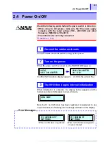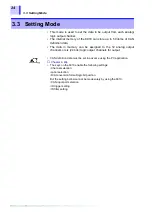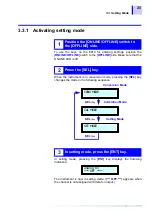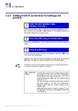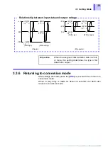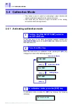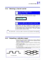
3.3 Setting Mode
26
3.3.2
Contents of display in setting mode
When the data to be output is assigned, the label name and D/A
conversion format ([
B
] or [
M
]) of CAN definition data are indicated for
an analog channel; the label name and bit position are indicated for a
logic channel.
3.3.3
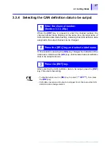
Selecting a channel number
When setting mode is activated, the channel number on the LCD
flashes, indicating that the channel selection can be changed.
In this condition, each time the [
SEL
] key is pressed, the channel
indicated on the LCD changes sequentially from analog channel 1 to
12. After analog channel 12, logic channels are shown in order of [
A0
]
to [
F3
], then the indication returns to analog channel 1. Hold down the
[
SEL
] key until the desired channel is shown.
After selecting a channel, press the [
ENT
] key. This enters the new
setting.
<Example of display for analog channel>
Analog 01
labelname M
Logic A0
labelname 0
<Example of display for logic channel>
1
Activating setting mode (Section 3.3.1, 25p.)
2
Push the [SEL] key, and select a channel.
01
→
02
→
03
…
12
→
A0
→
A1
→
A2
→
A3
→
B0
→
B1
→
B2
→
B3
→
C0
→
C1
→
C2
→
C3
→
D0
→
D1
→
D2
→
D3
→
E0
→
E1
→
E2
→
E3
→
F0
→
F1
→
F2
→
F3
→
(returns to the beginning)
CH
3
Push the [ENT] key.
Since CAN data conversion and output are in process for all channels
during channel number selection, the setting can be changed while
observing the output.
Summary of Contents for 8910
Page 1: ...8910 Instruction Manual CAN ADAPTER EN Aug 2018 Revised edition 7 8910A981 07 18 08H ...
Page 2: ......
Page 8: ...Contents vi ...
Page 18: ...Notes on Use 10 ...
Page 44: ...3 5 Operation Map 36 ...
Page 48: ...4 2 Program Setup 40 ...
Page 56: ...5 4 Operation Flowchart 48 ...
Page 78: ...6 6 Editing in Another Window 70 ...
Page 90: ...7 4 Setting the ID Filter 82 ...
Page 99: ...91 9 2 Setting Data Printout ...
Page 130: ...10 2 Using the 8910 with the 8841 8842 MEMORY HiCORDER 122 ...
Page 147: ......
Page 148: ......
Page 149: ......
Page 150: ......

