23
3.1 Modes
The 8910 has the following three operation modes, which can be
switched by using keys on the front panel.
• Conversion mode is the first mode to become active after power is
turned on.
• This mode converts the CAN message supplied to CAN1 or CAN2
port according to internally set definition data, and outputs the
converted signal from a specified analog or logic output terminal.
When conversion mode is active, the LCD indicates the following:
• The 8910 monitors the CAN bus and adjusts the baud rate
automatically. Therefore, the instrument has already begun to
receive signal input from CAN1 or CAN2 at this point.
• When the CAN message assigned to the output channel enters the
CAN port, the CAN LED goes on in green.
Operation
Chapter 3
3.1 Modes
Conversion mode
This mode converts the CAN signal input from
the CAN 1 or 2 port according to the set
definition data, and outputs the converted
signal from the specified analog or logic output
terminal.
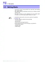
Setting mode
This mode is used to select data to be
acquired from the CAN bus and set the
channel for acquired data output.
Calibration mode
This mode outputs a calibration signal.
3.2 Conversion Mode
CONV MODE
• The output voltage level is held until conversion of the next CAN
message.
• Four baud rates are supported: 125 kbps, 250 kbps, 500 kbps, and 1
Mbps.
Summary of Contents for 8910
Page 1: ...8910 Instruction Manual CAN ADAPTER EN Aug 2018 Revised edition 7 8910A981 07 18 08H ...
Page 2: ......
Page 8: ...Contents vi ...
Page 18: ...Notes on Use 10 ...
Page 44: ...3 5 Operation Map 36 ...
Page 48: ...4 2 Program Setup 40 ...
Page 56: ...5 4 Operation Flowchart 48 ...
Page 78: ...6 6 Editing in Another Window 70 ...
Page 90: ...7 4 Setting the ID Filter 82 ...
Page 99: ...91 9 2 Setting Data Printout ...
Page 130: ...10 2 Using the 8910 with the 8841 8842 MEMORY HiCORDER 122 ...
Page 147: ......
Page 148: ......
Page 149: ......
Page 150: ......

