65
Chapter 5 Hardware Maintenance and Replacement
|
Hillstone
Hillstone SG-6000 X-Series Hardware Reference Guide
Chapter 5 Hardware Maintenance and Replacement
Overview
This chapter provides information on how to maintain and replace power module,
expansion module and fan tray.
General Maintenance
For optimum performance, use the following routine maintenance procedures:
Inspect the installation site for moisture, temperature and cleanness according
to the
Check the cables and make sure they are not loosened.
Inspect the air inlet and outlet. Make sure that there is no object blocking the
air inlet and the air outlet has not gathered any heavy dust. If the dust is so
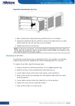
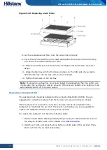
thick that it blocks the air flow, clean the cooling system or replace a fan tray.
See
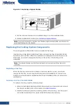
Replacing the Cooling System Components
When you maintain the hardware components, note that:
Always wear ESD strap on around your bare wrist. See
When you inspect or move the modules, hold the module with both hands
without touching the electric components on the module.
The removed module should be placed into an antistatic bag or on an antistatic table
with component-side up.
Tools Required
Cross screwdriver
ESD wrist strap
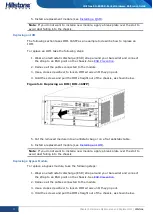
Replacing a Power Module
SG-6000-X10800 supports (3+1) x2 power module redundancy. If you remove one
power module out of the chassis which has four or more power modules, the system
can still work. If you remove one power module from the device with only three
power modules, system will not work normally.
SG-6000-X7180 supports 2+2 power module redundancy. If you remove one power
module out of the chassis which has three or four power modules, the system can still
work. If you remove one power module from the device with only two power modules,
other modules except the SCM(s) will stop working.

