


July 02
Machine Parameters
TNC 370 D
4–55
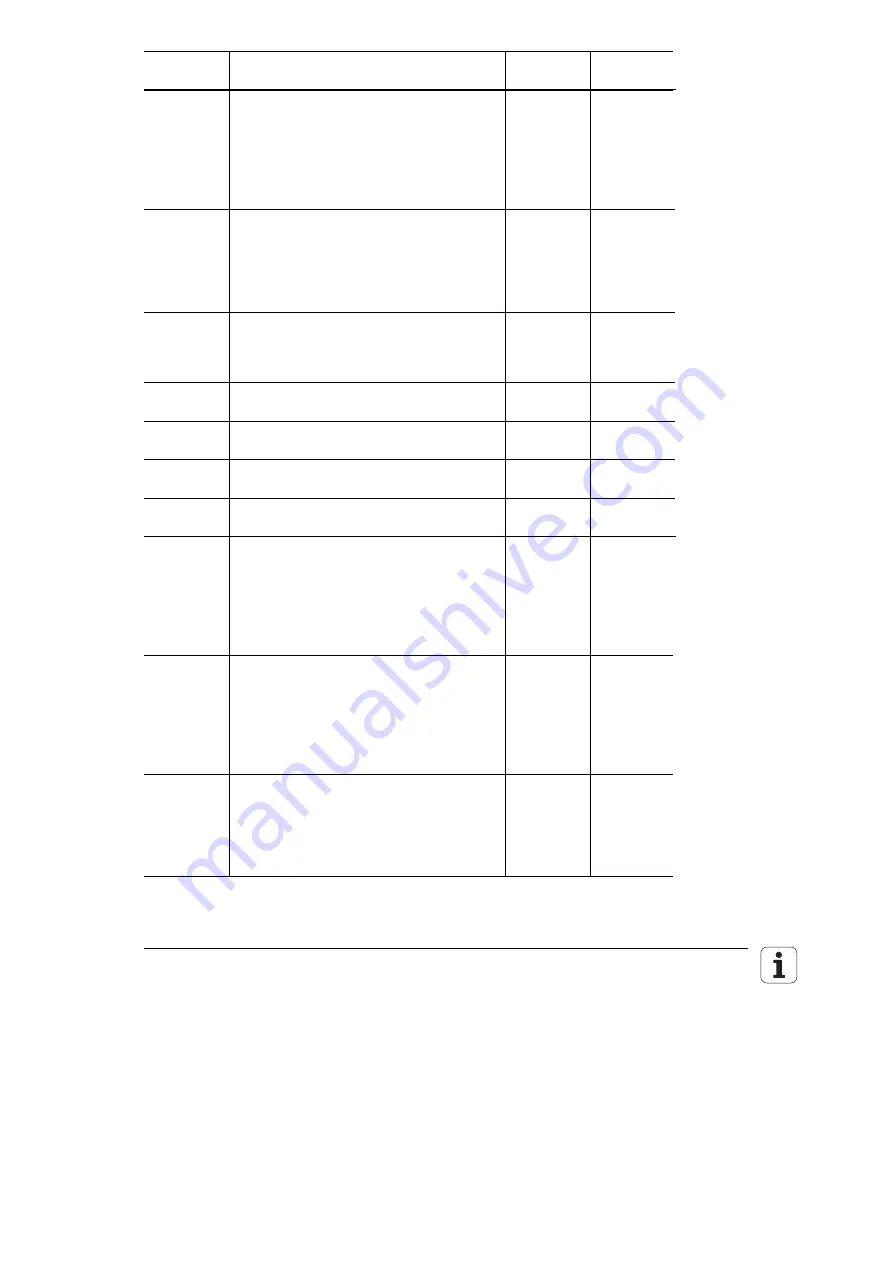
Machine
parameter
Function and input
Change via
Reaction
MP410.3
Axis identification for axis 4
Input: 0 = A
1 = B
2 = C
3 = U
4 = V
5 = W
MP420.3
Activation of Hirth coupling for 4
th
axis
Input:
0 or 1
(the MP can be read by the PLC, currently it
has no other function in the NC)
0 = Hirth coupling not active
1 = Hirth coupling active
MP430.3
Prescribed jog increment for Hirth coupling
(the MP can be read by the PLC, currently it
has no other function in the NC)
Input:
0.000 to 30.000[
°
]
MP710.0-3 Backlash compensation
Input: –1.000 to +1.000 [mm] or
[°]
PLC
MP711.0-3
Height of reversal spikes during rotation
Input: 0 –1.000 to +1.000 [mm]
PLC
RUN
MP712.0-3
Compensation value per CLP cycle time
Input:
0.000 to +1.000 [mm]
PLC
RUN
MP720.0-3
Linear axis-error compensation
Input:
–1.0000 to +1.0000 [mm/m]
PLC
MP 730
Selection of linear or non-linear axis-error
compensation
Input: %xxxx
0 = linear axis-error compensation
1 = non-linear axis-error compensation
Bit 0 to 3 0 = non-active
Axis X to 4 1 = active
Reset
MP810.0-3
Display mode for rotary axes and PLC
auxiliary axes
Input:
0.000 to 99 999.999[°]
0 = display
±
99 999.999;
Software limit switch active
¹
0 = modulo value for display;
Software limit switch inactive
PLC
MP910.0-3
Positive software limit switch for traverse
range 1; default setting after power-on;
activation via PLC M4575 = 0, M4574 = 0
Input: –30 000.000 to +30 000.000 [mm] or
[°] (Input values are referenced to the
machine datum)
PLC
Summary of Contents for TNC 370 D
Page 1: ... z ad snnn Technical Information NC Software 286 02x xx ...
Page 44: ...3 9 Mounting Dimensions LE 370 D July 02 Mounting and Electrical Installation TNC 370 D 3 41 ...
Page 48: ...July 02 Mounting and Electrical Installation TNC 370 D 3 45 3 11 Grounding plan ...
Page 49: ...3 46 TNC 370 D Mounting and Electrical Installation July 02 ...


