background image

After saving the equipment, the interlock statement will change to include your selected equipment.  

Verify that the interlock statement correctly states the interlock that you would like to create and then 

press save to create the interlock.

Configuration Summary 

The OmniHub displays all configured equipment in a table for you to view. 

Scroll through all configured devices and make sure they've been properly assigned.  

Finished with Configuration 

Now that all equipment has been configured, select the following:

Customizing / Add Components -

 use this selection to go back into Configuration and make 

changes.

Save and Restart -

 this selection will save your configuration settings and restart the Omni-

Hub. 

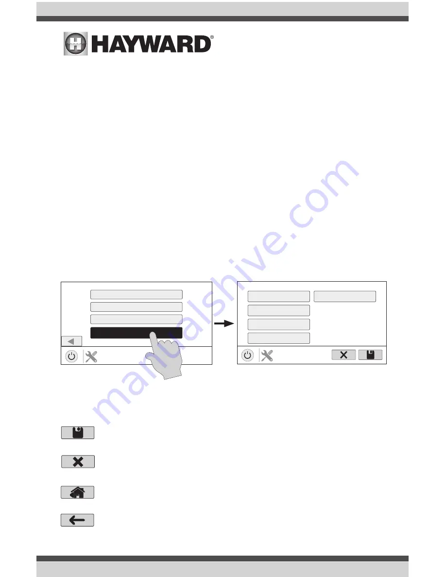
Quick Edit Guide

If additional pool or backyard equipment is added after initial configuration, or you’d like to make a 

change to an existing configuration setting, re-enter the Configuration Wizard and select “Edit”.  Af-

ter selecting “Edit”, you will be brought to the Quick Edit Main Menu screen as shown below.  Quick 

Edit allows you to go directly to the equipment that you’d like to add/remove/configure.  When you 

have finished editing the configuration, you will return to this screen to save your changes. 

Navigation

There are a number of additional buttons that appear in Quick Edit that either have functions unique 

to Quick Edit or do not appear anywhere else in the system.  These buttons are as follows:


Save

 - Touch this button to save the configuration edit.  This button only appears on the 

Quick Edit Home screen.


Cancel

 - Touch this button to cancel any changes made to the configuration and exit 

Quick Edit.  This button only appears on the Quick Edit Home Screen.


Home

 - Touch this button to quickly jump back to the Quick Edit Main Menu Screen to 

save your changes.  This button appears at the end of every configuration pathway.

Pre Programmed Config (VSP, Htr, Lt) 

New Typical Configuration

New Advanced Configuration

QUICK EDIT

configuration

Edit Current Configuration

QUICK EDIT

configuration

Main Menu

Bodies of Water

Backyard

Sensors

Add Interlock

System Options

47

USE ONLY HAYWARD GENUINE REPLACEMENT PARTS

Summary of Contents for OmniHub

Page 1: ...h NJ 07207 Phone 908 355 7995 www hayward com OmniHub Pool Automation Control Installation Manual Contents Before you Begin 3 Mounting 8 Plumbing 10 Wiring 11 Startup 23 Configuration 24 092711 RevA HLOMNIHUB USE ONLY HAYWARD GENUINE REPLACEMENT PARTS ...

Page 2: ...e harmful interference to radio communications However there is no guarantee that interference will not occur in a particular installation If this equipment does cause harmful interference to radio or television reception which can be determined by turning the equipment off and on the user is encouraged to try to correct the interference by one or more of the following measures Reorient or relocat...

Page 3: ...rs 10 Plumbing 10 Electrical Wiring High Voltage 12 Low Voltage 18 System Startup 23 Configuration Pre Programmed Configuration 26 Typical Configuration 27 Advanced Configuration 29 Quick Edit 47 Control Pad MountingTemplate 57 USE ONLY HAYWARD GENUINE REPLACEMENT PARTS 2 USE ONLY HAYWARD GENUINE REPLACEMENT PARTS 2 ...

Page 4: ... that you may need to complete an installation include Wire Wire conduit for incoming power Wire for remote variable speed pump control and other low voltage devices Ethernet cable if not using wifi Miscellaneous Valve actuator to automate pool functions Flow switch for optional pump protection flow monitoring A flow switch is required if using Sense and Dispense accessories Mounting hardware for ...

Page 5: ...cal dispensers and more controls up to two valve actuators allowing you to manage two bodies of water both pool and spa or can be used for water features cleaners solar heating etc controls one conventional heater electric heat pump or gas and optional solar heater for single body of water applications only inputs for up to 3 temperature sensors or external input devices built in wireless to conne...

Page 6: ...fi won t be used Smart Relay Smart Relays have a 15 ft communication cable that connects to the Wiring Hub and are used to control high voltage pool equipment like lights water features pumps and more 115 VAC or 230 VAC power to the intended load must be supplied separately and run through the Smart Relay Smart Relays are rated for up to 20 amps at 230 volts Temperature Sensors Depending on your i...

Page 7: ... etc Variable Speed Pump Filter Valve Actuator Heater TO POOL FROM POOL Power to VSP if same voltage as Hub Input Power to Smart Relay 1 Comm to Smart Relay 1 15 Heater Remote Control Comm to Valve Actuator Comm to VSP To Solar REMOTE RELAY OFFLINE ON OFF Smart Relay 1 Input Power Comm to Smart Relay 2 15 Control Pad To Feature Accessory Lights etc Wireless Connection OR Ethernet to Router Comm to...

Page 8: ...niHub is designed to be mounted outdoors at the pool pad Both the Wiring Hub and the Control Pad are water resistant and can be left out for the winter Details on each installation step are shown below 1 Mounting the equipment page 8 Wiring Hub Control Pad Smart Relay Temperature sensors Valve actuators if applicable 2 Plumbing page 10 General Pool Equipment Flow Switch 3 Electrical Wiring page 11...

Page 9: ... has two keyhole type mounting tabs on the top and bottom of the enclosure requiring a total of 4 fasteners Control Pad The Control Pad comes with a 15 ft cord and plugs into the Wiring Hub It should be mounted in a location that is convenient for the user to view and change pool spa settings When considering the mounting location make sure there is enough clearance above the enclosure so that the...

Page 10: ...ess to the pool equipment that you intend to control with the Smart Relay Three threaded 1 2 NPT knockouts are provided for high voltage power coming into the relay and for power out to the pool equipment A Wiring Whip is included to aid installation The Smart Relay has a manual On Off button that can be used if communication is lost with the Wiring Hub Although this button is not functional durin...

Page 11: ...e note that the internal cams in the actuator may have to be adjusted depending on the way the actuator is mounted on the valve and the desired valve action Plumbing Flow Switch A Hayward GLX FLO flow switch sold separately is required if an HL CHEM ORP pH Sensing Kit will be used If no chemistry equipment is installed the GLX FLO is optional and can be used to detect leaks or clogs in your pool s...

Page 12: ...Wiring Hub has been provided for all low voltage wiring All low voltage wires should run through this channel to exit the Wiring Hub A weather resistant gasket is provided see page 23 to seal this exit Input Power Flow Switch Smart Relays Variable Speed Pumps Sense Dispense Aqua Rite Communication Temperature Sensors External Input Heater Control Pad Valve Actuators Wiring Channel Low Voltage Grou...

Page 13: ...rmation Powering Hub and VSP with Same Voltage Variable speed filter pumps require constant power and are turned on and off through low voltage communication wiring from the OmniHub Because the OmniHub must also be powered continu ously it may be most convenient to wire the VSP and OmniHub in parallel on the same circuit If this is the case they must both be powered by the same voltage An example ...

Page 14: ... it must be set to run continuously Powering Hub and Single Speed Pump with Same Voltage Single speed pumps require the use of Smart Relay s High voltage connections are made directly to Smart Relays which are turned on and off through a low voltage communication connection to the OmniHub Like the OmniHub Smart Relays can be powered by either 115 VAC or 230 VAC Connect 115 VAC from the panel timec...

Page 15: ... 115 VAC pump is then wired to the output side of the Smart Relay Note that this connection method will work for 230 VAC using the 230 VAC connections on the Smart Relay Connect to Hub and Smart Relay L1 N 115VAC Ground Disconnect from existing 115 VAC pump Wiring Whip to Smart Relay 115 VAC Existing Timeclock or Switch Must be same for Hub and Pump wired through a Smart Relay Smart Relay New 115 ...

Page 16: ...utput side of the Smart Relay is then wired to the pump Connect 230 VAC directly to the input side of the Smart Relay Disconnect 230 VAC from existing pump 230 VAC to Smart Relay Existing Timeclock Switch Outlet or Panel Smart Relay Electrical Panel Ground L2 L1 115 VAC to Hub Connect exist ing pump to 230 VAC output side of Smart Relay Black White Gray Black Red White Red Line 2 in Line 1 in Line...

Page 17: ...hip if the supplied electrical box will be mounted within 6 ft of the power source Red black and green conductors are included for 230 VAC wiring A white conductor is supplied if using 115 VAC input power Use the included wire nuts for wiring connections Use proper threaded strain relief fittings when attaching conduit to knockouts After wiring is complete carefully insert the cover with connectio...

Page 18: ...ing normal operation Refer to the table below when viewing the Smart Relay s indicator LEDs Note that when the Relay On LED is OFF the relay is in an OFF state and there is no power going out to the load When Green the relay is energized and the load receives power Remote LED Relay On LED Indication Off Off No power or firmware failure Red On for 1 sec Off for 6 sec Off or Green There is no commun...

Page 19: ...munication wiring instructions Up to three VSPs can be controlled by the OmniHub VSP Communication Wiring Disconnect onboard display and set all dipswitches to OFF position TriStar VS 950 Omni Super Pump VS 700 Omni MaxFlo VS 500 Omni Pump Conn Hub Conn 7 2 8 3 A 2 B 3 COM 4 TriStar VS 900 Omni For pump models with dip switches set all switches to OFF position as shown Remove the display cable Use...

Page 20: ...hat plug directly into the Hub as shown on page 11 Temperature Sensors The Wiring Hub utilizes 10K ohm thermistor type sensors with 15 ft cable If a longer cable is re quired contact the Hayward service dept 908 355 7995 for information on suitable cable types and splices Temperature sensors are wired to the 8 position connector shown on page 11 and on the follow ing page To unlock push on the cor...

Page 21: ...orced on or off when the external device is activated Control Pad The Control Pad has a 15 ft cable with a connector that plugs directly into the Wiring Hub as shown on page 11 There are rubber plugs covering USB port and Ethernet port on the bottom of the Control Pad enclosure The Ethernet port is available if a wired connection to the access point is desired over the built in wifi The USB port i...

Page 22: ... generate chlorine based on the pool s ORP level using HL CHEM or as a percentage of run time producing small amounts periodically throughout the day The standard Aqua Rite requires an HLAQRPCB communication board sold separately and connects to the OmniHub in the same manner as a Smart Relay The HLAQR940 bundle OmniHub AQR940 Aqua Rite contains the HLAQRPCB kit which can be used with minor Heater...

Page 23: ...to the home router For wireless connections refer to the Configuration section of this manual For Ethernet connections use outdoor rated Cat5e or Cat6 Ethernet cable Connect one end to the Control Pad and the other to an available LAN port not WAN on the home router or access point Refer to the diagram below Remove Cover to Access Junction Box Remove Jumper Ethernet port Router LAN port USE ONLY H...

Page 24: ...the OmniHub The OmniHub will take about 30 seconds to fully start Firmware Upgrade The OmniHub s firmware is the basic operating system that runs the system The OmniHub was shipped with the version of firmware that was available at the time of release There may be a newer version available and if so we encourage you to upgrade Also if you have experienced problems Hayward Technical Support may adv...

Page 25: ...gure the OmniHub unless you can dedicate at least 15 minutes or more Configur ing the OmniHub requires knowledge of all of the connected pool equipment If you are asked a question and don t know the answer in many cases you ll be able to skip the question and proceed In some cases the Configuration Wizard will require an answer Answer the question to the best of your ability and take note as you l...

Page 26: ...ion The Configuration Wizard has been designed to be intuitive allowing most users the ability to navi gate with little instruction A list of commonly used buttons is shown below Done Touch this button to complete your selection Cancel Touch this button to cancel your selection Advance Touch this button to advance to the next screen Back Touch this button to return to the previous screen Add Touch...

Page 27: ...you input the password and press the check mark to continue a Network Diagnostic screen will appear and the OmniHub will run through a series of checks to verify connection to the access point When the system is done running through the diagnostics press the check mark to continue to the next section of the Configuration Wizard If No is selected Choose an option below External Wireless Make this s...

Page 28: ...nect to you home network Refer to the Connect to Home Network section on page 26 for more information on this part of the Configuration Wizard Time and Date Set the current date and time using a 12hr clocone button when finished NOTE When registering the OmniHub and creating a web account you ll be prompted to enter a Time Zone Be sure to enter the same time zone as the physical location of the Om...

Page 29: ...one variable speed pump is discovered If Yes is selected Select the type of pump driven accessory water feature cleaner accessory If Water Feature Cleaner or Accessory is selected Which Hayward Unique Address Select the HUA of the water feature clean er or accessory s variable speed pump NOTE this option only appears if more than two variable speed pumps are discovered With only two variable speed...

Page 30: ... in ppm If Metric is selected temperatures will be displayed in Celsius and chemistry readings will be in g L Select Desired Units of Measure Speed in or Speed in RPM If Speed in is selected then pump speeds will be displayed in If Speed in RPM is selected then pump speeds will be displayed in RPM MSP ID The OmniHub MSP ID number will be displayed This unique number is used to identify your OmniHu...

Page 31: ...le and touch the Done button to proceed The Smart Relay s should now be shown in the box es and you can advance to the next screen to continue the pump configuration Filter Pump Off for Valve Change When Yes is selected the pump will shut off for 35 seconds whenever a valve changes position Flow Monitoring Enabled Requires use of a Hayward flow switch This feature will help protect the filter pump...

Page 32: ...Speed Presets Set the Low Pump Speed Medium Pump Speed and High Pump Speed presets These presets will be used when setting schedules for your pump Filter Pump Off for Valve Change When Yes is selected the pump will shut off for 35 seconds whenever the valve s change position Flow Monitoring Enabled Requires use of a Hayward flow switch This feature will help protect the filter pump from damage due...

Page 33: ...ater extend will NOT cause the filter pump to turn on it will only delay the turn off time when the heater is operating Maximum Settable Temperature This is the maximum allowed setting for the heater regardless of its default range There may be circumstances where you will want to limit the high temperature of your heater to a temperature that is lower than the factory high setting Select and Conf...

Page 34: ...ed Note that a time interval setting of 0 will eliminate priority and always run both heaters at the same time Minimum Allowed Air Temperature for Heater If the air temperature falls below this setting the heater will be prevented from running regardless of conditions This feature is especially useful for heat pumps which become less efficient as the outdoor ambient temperature falls Minimum Opera...

Page 35: ...for the solar heating system to operate properly Do you have a Sense Dispense Module Select Yes if a Hayward HL CHEM sold separately is connected to the OmniHub If Yes is selected The next few screens will configure the OmniHub to use Sense and Dispense The Omni Hub automatically detects smart components like the HL CHEM and assigns a Hayward Unique Address If multiple components are detected the ...

Page 36: ...e detected cell Se lect the TurboCell and select Done If Liquid Chlorinator is selected Select Relay Selecting the box will bring you to a table show ing all Smart Relays Select the Smart Relay that is connected to the Liquid Chlorine dispenser If Tablet Feeder is selected Where is the Valve Wired Selecting the box will bring you to a table showing all valve outputs Find the valve that is con nect...

Page 37: ...point How many cleaners The OmniHub has two actuator outputs If controlling a pool and spa two bodies of water you cannot add a cleaner that requires a valve If 1 or more is selected Select and Configure a Cleaner At this screen you can add delete and configure your cleaner s Select the desired cleaner then touch the Advance button When finished configuring cleaner s you ll be returned to this sam...

Page 38: ...n in use If Yes is selected How Many Select how many valves are used for the cleaner Where is the Valve s Wired Selecting the box will bring you to a table show ing the valve outputs Select the output s that is wired to the cleaner valve s then advance Advance to the next screen to continue Would you like your valve s to cycle On and Off at a set interval If you would like the cleaner valve s to c...

Page 39: ...e speed or two speed pump is selected Which Relay is it Wired to If using a single speed or two speed pump you ll be asked which Smart Relay s is wired to the pump If a value is already shown in the box es advance to the next screen If no value is shown selecting the box will bring you to a table showing all detected Smart Relays Select the proper Smart Relay s from the table and touch the Done bu...

Page 40: ...ting is configurable from 0 15 minutes Once priming has finished the pump will run in the speed that it was chosen to run at Freeze Protection Enabled Freeze protection is used to protect the pool and plumbed equipment against freeze damage during cold temperatures If freeze protection is en abled AND the air temperature falls below the freeze threshold refer to pump configura tion the OmniHub wil...

Page 41: ...s is selected What Type Select the type of pump used The choices are Single Speed Two Speed and VSP If single speed or two speed pump is selected Which Relay is it Wired to If using a single speed or two speed pump you ll be asked which relay s is wired to the pump If a value is already shown in the box es advance to the next screen If no value is shown selecting the box will bring you to a table ...

Page 42: ... Yes is selected Enter Priming Duration Input the number of minutes that you want the pump to prime for This setting is configurable from 0 15 minutes Once priming has finished the pump will run in the speed that it was chosen to run at Freeze Protection Enabled Freeze protection is used to protect the pool and plumbed equipment against freeze damage during cold temperatures If freeze protection i...

Page 43: ... sensors Where is the Sensor Located Touch the box and go to the table showing the Bodies of Water and the Backyard Select the location where the sensor is installed What Type of Sensor Select the type of sensor Choices are Air Water Flow or Solar Name Sensor Touch the box and use the keyboard to name the sensor Where is the Sensor Wired Touching the box will bring you to a table showing all detec...

Page 44: ...uld be the desire to turn on walkway lighting slave every time the pool deck lights master are turned on This equipment could have been wired together to accomplish the same function but by interlocking the walkway lights to the deck lights you ll maintain the ability to turn on the walkway lights independently An interlock can also control pool equipment based on the state of a temperature sensor...

Page 45: ...erify that the interlock statement correctly states the in terlock that you would like to create and then press save to create the interlock If Equipment to Flow Switch is selected Select Interlock Statement Use the right and left arrows to choose the de sired behavior of the interlock The behavior for each interlock statement is described If the Flow Switch detects no flow the Equipment can not b...

Page 46: ...t can be controlled independently as long as the External Input is open If the External Input is open the Equipment can not be on The Equipment can only turn on if the External Input is closed If the Equipment is running and then the External Input becomes open the Equipment will turn off The Equip ment can be controlled independently as long as the External Input is closed If the External Input i...

Page 47: ...ture goes below the selected Temperature setpoint the Equipment will turn off The Equipment can be controlled independently as long as the Temp Sensor reads greater than the selected Temperature setpoint If the Temp Sensor reads greater than Temperature degrees F the Equip ment is forced on The Equipment is always off until the Temp Sensor reads greater than the selected Temperature setpoint at wh...

Page 48: ...ught to the Quick Edit Main Menu screen as shown below Quick Edit allows you to go directly to the equipment that you d like to add remove configure When you have finished editing the configuration you will return to this screen to save your changes Navigation There are a number of additional buttons that appear in Quick Edit that either have functions unique to Quick Edit or do not appear anywher...

Page 49: ...Water Features Standalone Lights Accessories and Other Options If the equipment is not already configured then the buttons will appear as Add Heater Add Cleaner etc When the button is pressed with the word Add before it then you will be taken through the full configuration for that equipment as appears in the Advanced Configuration Guide section of this manual Otherwise If Filter Pumps is selected...

Page 50: ...d up to the desired temperature setting Heater extend will NOT cause the filter pump to turn on it will only delay the turn off time when the heater is operating Cooldown This feature ensures that the heater cools down before water cir culation is stopped When enabled the OmniHub will continue to run the filter pump for 5 minutes after the heater turns off Max Temperature Select the maximum allowe...

Page 51: ...ns are as follows Reduction ON Select whether you want pH reduction to be enabled Chemical Type Select the type of chemical that is being dispensed acid or CO2 pH Dispensers Configure the pH dispense unit pH Timeout Choose the pH timeout time pH Extend Select whether you want pH extend enabled for this Body of Water Chem Sense Module Once you select Chem Sense Module you will be able to select the...

Page 52: ... type of cleaner that is configured Pressure Suction Robotic In Floor Pump Configure the cleaner pump if used Relay Select the Smart Relay that is wired to the cleaner This option only ap pears if the cleaner does not have an associated pump configured Valve Configure the cleaner valve if used Freeze Protect Select whether you want the cleaner to turn on for Freeze Pro tection Also set the Freeze ...

Page 53: ...ed settings This option only appears if the water feature pump is configured as a VSP Priming Select whether you want the water feature pump to prime This option is only available if the water feature pump is configured as a 2 Speed or VSP Freeze Protect Select whether you want the water feature to turn on for Freeze Protection Also set the Freeze Protect air temperature threshold from this menu D...

Page 54: ...me Create a custom name if desired Type Select the type of accessory configured Laminar Dimmer etc Pump Configure the accessory pump if used Valve Configure the accessory valve if used Speed Change the minimum and maximum allowed speeds of the accessory pump as well as the Low Medium and High speed settings This option only appears if the accessory pump is configured as a VSP Priming Select whethe...

Page 55: ...ct the Delete button on the right of the name of the lights group that you wish to delete If Sensors is selected Add Sensor Pressing Add Sensor from this screen will take you through the full configura tion for adding a new sensor These steps are described in the Advanced Configuration Guide section of this manual Select a Sensor Once you select a sensor all of the options for that sensor will app...

Page 56: ...Once you input the password and press the check mark to continue a Network Diagnostic screen will appear and the OmniHub will run through a series of checks to verify connection to the access point When the system is done running through the diagnostics press the check mark to continue to the next section of the Configuration Wizard If No is selected Choose an option below External Wireless Make t...

Page 57: ...USE ONLY HAYWARD GENUINE REPLACEMENT PARTS 56 ...

Page 58: ...Control Pad Mounting Template 57 USE ONLY HAYWARD GENUINE REPLACEMENT PARTS ...

Page 59: ...For more information on authorized service centers please contact the Hayward Technical Service Support Center 61 Whitecap Road North Kingstown RI 02852 or visit the Hayward web site at www hayward com WARRANTY EXCLUSIONS 1 Material supplied or workmanship performed by others in process of installation 2 Damage resulting from improper installation including installation on pools larger than the pr...

Page 60: ...demark and OmniHub is a trademark of Hayward Industries Inc 2018 Hayward Industries Inc All other trademarks not owned by Hayward are the property of their respective owners Hayward is not in any way affiliated with or endorsed by those third parties USE ONLY HAYWARD GENUINE REPLACEMENT PARTS USE ONLY HAYWARD GENUINE REPLACEMENT PARTS ...

Reviews: