


No. 2 batteries to PS1 and PS2 bus bars. When
the indicated rates of charge reduce to less
than 5 amps, EXT BATT CHG switch should
be positioned to OFF.
With PE bus bar energized, the relevant BATT
1 or 2 CNTCTR annunciator illuminates when-
ever the associated No. 1 or No. 2 battery con-
tactor or emergency contactor is deenergized.
NOTE
If, during external charging, a bat-
tery becomes hot or ground supply
voltages become abnormal, Nos. 1
and 2 batteries are automatically iso-
lated from the airplane bus bars, and
battery charging ceases.
If battery isolation is due to battery
overheat, charging automatically re-
sumes when battery temperature
drops to a safe level.
In the event of battery isolation due
to abnormal ground supply voltages,
turn the EXT PWR switch off, dis-
connect the ground supply, investi-
gate, and rectify. Position the BUS
TIE switch to CLOSE before at-
tempting to reinstate.
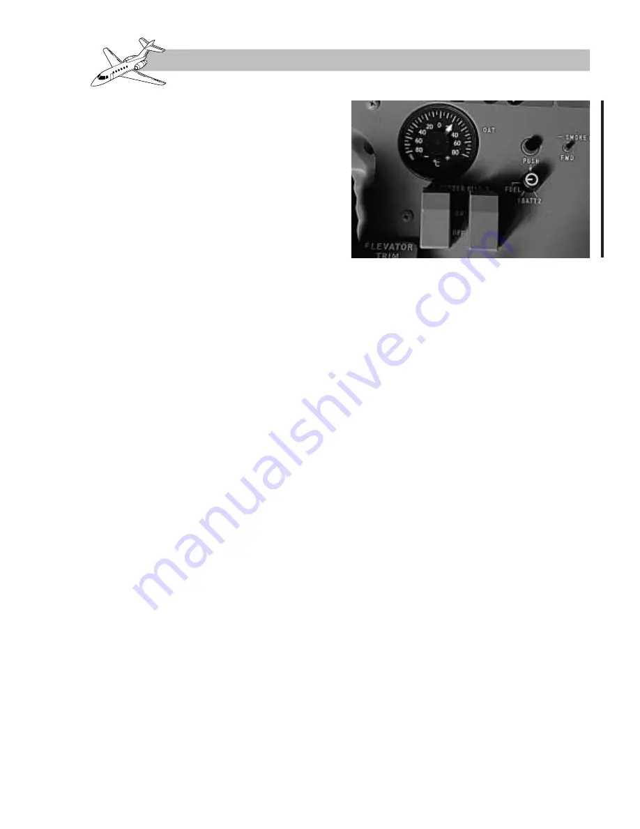
Battery Temperature Indication
(Nicad Batteries Only)
A combined outside air, fuel, battery 1 and 2
indicator is located on the central control
pedestal. Temperature sensors fitted integral
with No. 1 and No. 2 batteries are electrically
connected to the indicator via a rotary selec-
tor switch and a push-button switch (Figure 2-
6 ) . T h e r e l eva n t b a t t e r y t e m p e r a t u r e i s
indicated when the pushbutton is pressed and
the adjacent switch is set to BAT 1 or 2.
GENERATORS
A 30-volt DC, 400-ampere starter-generator is
mounted on each engine. The generators are
self-exciting and produce rated power output
when the engine reaches self-sustaining speed.
Each generator is cooled from an air intake in
the engine cowling (Figure 2-7). The cooling
air is vented overboard via a duct in the lower
cowling. Cooling during ground operation is
provided by an integral fan on each generator.
The output voltage of each generator is sta-
bilized by an associated GCU. The GCUs pro-
vide load equalization when the generator
outputs are tied in parallel.
For engine starting, the generator operates as
a starter motor powered by a 28-VDC ground
supply or by the airplane main batteries con-
nected in parallel.
The generator controls, indicators, and an-
nunciators, with the exception of an ELECT
annunciator on the center instrument panel, are
all located on the roof panel.
Revision 1
2-7
FOR TRAINING PURPOSES ONLY
HAWKER 800 XP
PILOT TRAINING MANUAL
FlightSafety
international
Figure 2-6. Battery Temperature Indicator
Summary of Contents for 800 XP
Page 4: ......
Page 6: ......
Page 10: ......
Page 104: ......
Page 124: ......
Page 126: ......
Page 156: ......
Page 158: ......
Page 160: ......
Page 170: ......
Page 172: ......
Page 174: ......
Page 184: ......
Page 186: ......
Page 198: ......
Page 200: ......
Page 202: ......
Page 222: ......
Page 264: ......
Page 266: ......
Page 268: ......
Page 276: ......
Page 278: ......
Page 280: ......
Page 290: ......
Page 292: ......
Page 310: ......
Page 312: ......
Page 314: ......
Page 328: ......
Page 338: ......
Page 340: ......
Page 342: ......
Page 352: ......
Page 354: ......
Page 356: ......
Page 378: ......
Page 412: ......
Page 414: ......
Page 416: ......
Page 474: ......
Page 476: ......
Page 478: ......
Page 486: ......
Page 500: ......
Page 502: ......
Page 504: ......


