


Revision D • 8/05
H
A
R
R
I
S
C
O
R
P
O
R
A T
I
O
N
5-4
5 Service
digital
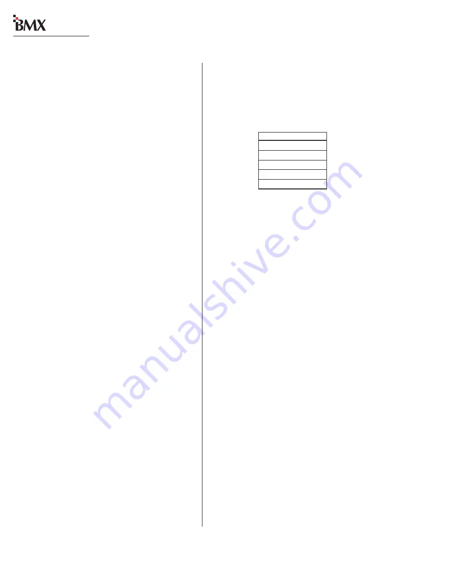
Both models are specifically setup for the main-
frame size the card is installed into through rotary
switches DS1 and DS2. The following table lists
the rotary switch settings by frame size.
NET CARD ROTARY SWITCH SETTINGS
FADER SERVICING
There are no replaceable nor rebuildable parts
on the BMX
digital fader assembly. Fader service
is comprised of cleaning and lubricating.
Faders are conductive plastic, single-element fad-
ers. If the fader movement is rough, either the lu-
bricant on the glide rails has evaporated or for-
eign material has gotten into the fader. Dow Corn-
ing 510 is the preferred glide rail lubricant as it
will not migrate to the contact fingers like other
lubricating oils.
Fader Disassembly and Cleaning
To disassemble and clean the faders:
1
Remove the module from the mainframe.
2
Remove the fader knob and the two fader
mounting screws, then remove the fader from
the switch assembly.
3
Remove the snap-on fader assembly cover. It
is held in place by plastic tabs.
4
Clean the fader using either a dry cotton swab
or a cotton swab dampened with distilled
water.
NOTE:
The use of chemical cleaners on the con-
ductive plastic will substantially shorten fader life.
Never touch the fader slider contact fingers while
cleaning the fader parts.
INSTALLING INPUT MODULES
To install a module into the mainframe:
1
Open the meter panel.
2
Lower the module into its slot. Be sure to align
the pins on the PCA with the motherboard
connector in the mainframe.
3
When the pins are aligned, press straight down
to seat the module. Do not force the module,
and do not press on buttons or connectors
while seating the module.
4
Fasten the module to the mainframe using two
38-88 screws and install the module ground-
ing screw.
NOTE:
If the module does not work after instal-
lation, remove the module and visually check to
make sure no connector pins are bent.
DSP AND NET CARD SERVICE INFO
Unlike the input, control room, studio or ses-
sion modules, DSP and Net cards cannot be re-
moved or plugged in with the console power on.
DSP Cards
There are two versions of DSP cards in use—
the original design (identified by a solid green LED
on each card, with one master DSP with 3-pin
MOD IV connector) and the current VistaMax-
compatible cards (identified by a flashing yellow
LED on each card with the left-most card auto-
matically set as the master—with an LED flash
rate that is twice as fast as the other DSP cards).
The two DSP card versions cannot be inter-
mixed, they must be replaced as a set. When a Net
card is installed, the current version (with the flash-
ing yellow LED) must be installed.
DSP cards of either version do not have any user
settings or adjustments.
Net Card
There are two Net card models available: with
optical and without optical VistaMax connctors.
Framesize DS1
DS2
8
6
1
14
7
1
22
8
1
30
A
2
38
B
2


