Four post parking lift Happ25 4 post hoist
17
•
Left picture E – Dual nut and washer fitting for cable
Internal latch
The internal latch uses the same end frame but contains the latches inside the cross beam as shown below.
Figure: End frame assemblies for internal locking mechanism
With the end frames installed the internal safety ladder is installed and cap assembly bolted to the top of column.
When the safety ladder passes through the cross beam the latches will engage. (This photo would not be visible
to an installer as it occurs inside the column)
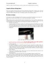
Figure: safety ladder installed into the cross beam. Note the safety latches extending past the ladder. The cross
beam my need to be raised if the latches are to be moved for cable adjustment.
Connect the cables
The cables have already been extended, and should now be able to be routed through the pulleys and up into the
cap assembly.
External lock.
The cable routes up to the top plate on the column.
You will put a washer then two nuts on each thread as shown below. Cable lengths can vary from time to time.
Spacers are available from HAPP if the thread does enable enough adjustment.
Figure: Correct orientation of bolts ( item B) , with thread to outside, trim off excess with cut of wheel if
desired.
The cable setup on the internal locking mechanism is similar to the external locking mechanism. With the
addition of the routing of the cable past the second safety release pulley as shown below. The cross beam may
need to be supported to allow the second safety pulley to be moved inwards allowing the cable to route in its
normal route (from pulley to top of column). A small wedge can be used to hold this pulley in preventing it
from impacting the cable route. If a wedge is used ensure it is removed before operation of the hoist.

