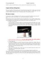
Four post parking lift Happ25 4 post hoist
16
Construct and attach end frames
•
The end frames consist of the columns and cross beam.
•
Lay each column down with a support under the top of column that will enable the top end of the
column to be slightly higher than the base.
•
Both sides need to be at approximately the same angle and at the width required to fit the cross beam.
•
Lubricate both column internals, pulleys and nylon runners with Wurth dry lube.
•
Slide the cross beam into the columns, and lower to bottom whilst holding the safety latch in the
release position.
•
Install the column cap assembly.
•
Move the end frames to the ends of the hoist.
•
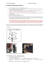
Using the bolts provided connect the cross beam to the runway. There are two larger end plates to stop
the car from over running the hoist that go onto the end of the hoist furthest from the entry end and two
smaller plates that are used at the entrance end as shown below.
•
Ensure that the head of the bolt is on the inside of the cross beam (where the cables run). Failure
to do so may cause the cables to hit the thread of the bolt. You may need to trim the bolt thread
on the outside with a 100mm angle grinder to avoid contact with the safety release mechanism.
There are two forms of safety latch available for the HAPP 25, internal and external latches. The internal latch
mechanism is typically used in workshop focused environments, the external in storage focused environments.
External latch
Figure: End frame assemblies external locking mechanism.
Note the following in relation to bottom two pictures:
•
Left picture A – Cap assembly bolted to column.
•
Left picture B – Pulley cover
•
Left picture C and Right picture B – correct threading representation on connecting bolts
•
Left picture C and Right picture A – difference in entre spacer plate ( C ) and end of ramp plate
( A ).
•
Left picture D – Lock out pin for extended storage protection

