background image

8

APP-001f 
SEPT 2016


SECTION 3 COMPONENT DESCRIPTIONS

TOUCHSCREEN

The Touchscreen is the operator’s interface with the 

APPT software. The Touchscreen display has two display 

modes, the Menu Display Mode and the Status Display 
Mode. The Status Display Mode will indicate the operating 
conditions and alert the operator of the inputs to the APPT. 

This is the display mode the APPT will most likely operate 

in. In the Menu Display Mode the operator can verify 
and in some cases change various system parameters, 
troubleshoot their APPT, or remove their data storage 

device. To switch between the two display modes press 

“ESC” on Touchscreen.

There are four navigation keys on the Touchscreen:

ESC – Switch between the status mode and menu mode, 
also used to exit back through menu mode.

/\ - Navigate up

\/ - Navigate down

ENTER – To enter a specific menu hierarchy or enter a 
parameter change

The Touchscreen is the operator’s interface with the 
APPT so4ware, see Figure 5. The Touchscreen display 
has two display modes, the menu mode and the 
status mode. The status mode will indicate the 
opera>ng condi>ons and alert the operator of any 
status of the APPT. This is the mode the APPT will 
most o4en operate in. The second mode is the menu 
mode. In this mode the operator can verify and in 
some cases change various system parameters, 
troubleshoot their APPT, or remove their data storage 
device. To switch between the two display modes 
press “ESC” on Touchscreen. 


There are four naviga>on keys on the Touchscreen: 


ESC – Switch between the status mode and menu 
mode, also used to exit back through menu mode. 


/\ - Navigate up 


\/ - Navigate down 


ENTER – To enter a specific menu hierarchy or enter a 
parameter change

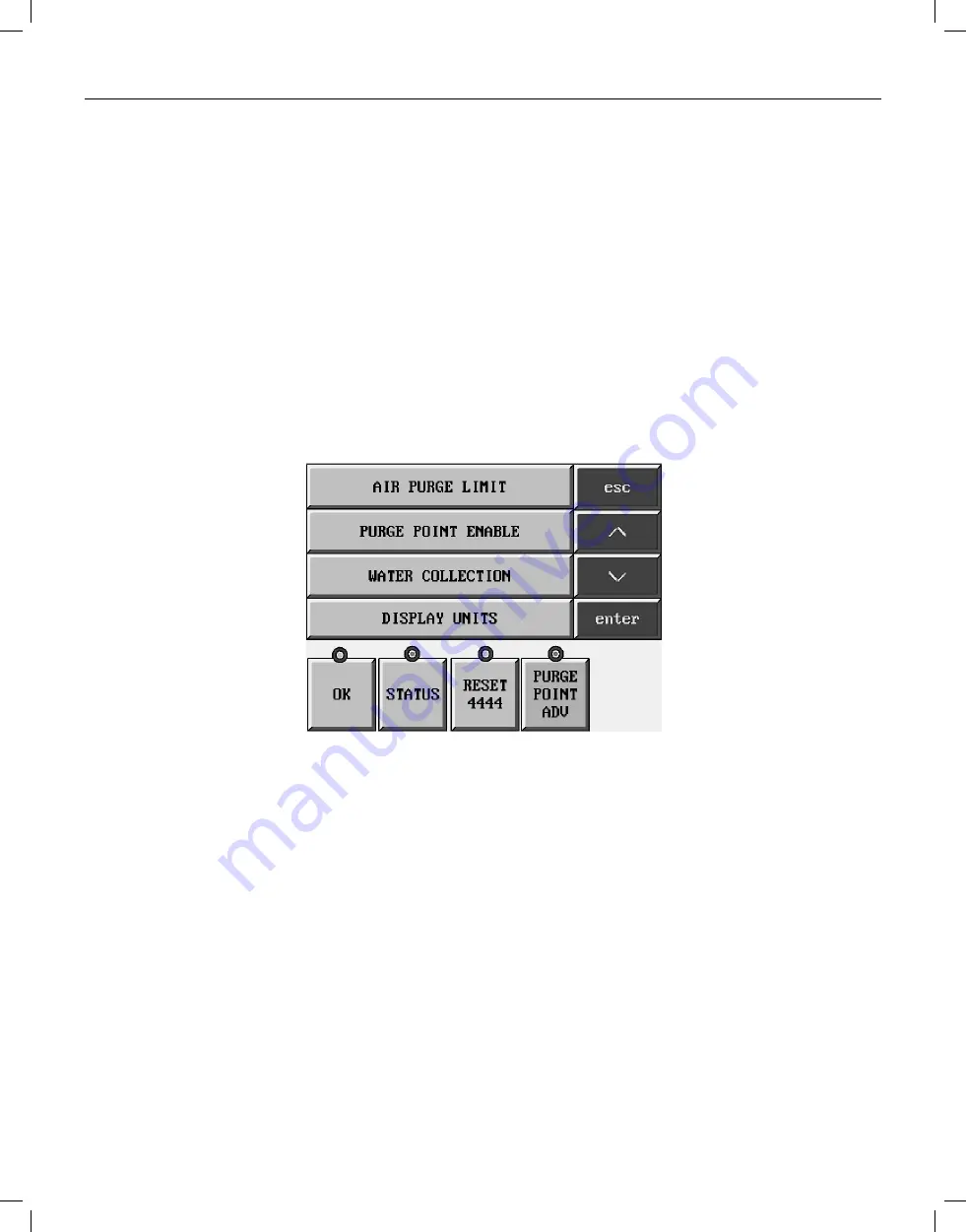
Auto-Purger Plus Technology Package Color Touchscreen 

Figure 6 


O


Along the boPom of the Touchscreen there are five func>onal keys for specific tasks. Each will have a green dot 
above it when the key can be used, see Figure 5. 


OK – This key will become ac>ve when the purger is 
ready to drain water following water concentra>on 
mode. It will need to be pressed when prompted to 
open the water purge solenoid and again when 
prompted to close the water purge solenoid. 


STATUS – Pressing this key will display the status 
screens of the opera>ng condi>ons of the APPT 
(there are eight status screens; see below). 

RESET 4444 – Reset 4444 alarm condi>on (see 
Sec>on 7 Troubleshoo>ng for explana>on of alarm). 


PURGE POINT ADV – This key is pressed to manually 
advance to the next purge point (key not applicable 
on APP(T)C model). 


Along the bottom of the control console there are four functional keys for specific tasks. Each will have a green dot 

above it when the key is available and a red dot above it when the key is unavailable.

OK

 – This key will become active when the purger is ready 

to drain water following water concentration mode. It will 
need to be pressed when prompted to open the water 
purge solenoid and again when prompted to close the 
water purge solenoid.

STATUS


– Pressing this key will display the status screens 

of the operating conditions of the APPT (there are eight 
status screens; see below).

RESET 4444

 – Reset 4444 alarm condition (see Section 

7 Troubleshooting for explanation of alarm).

PURGE POINT ADV


– This key is pressed to manually 

advance to the next purge point (key not applicable on 

APP(T)C model)

.

5

Summary of Contents for APPT08

Page 1: ...igerant noncondensible gas air and water purger for reducing the energy costs of operating an ammonia refrigeration system All models are preassembled pre wired insulated and include an automatic wate...

Page 2: ...nces only one point is effectively purged The best practice is to purge each condenser and receiver circuit separately It is extremely important to install purge points at locations sure to be liquid...

Page 3: ...pressor discharge main inlet Vertical condensers should be purged near the top of the vessel if possible For certain types of oil separators where very low velocities may exist near the top of the ves...

Page 4: ...quid ammonia that typically is also contaminated with water which is to be removed by the AUTO PURGER Plus The liquid line solenoid valve B on the AUTO PURGER Plus closes when the AUTO PURGER Plus is...

Page 5: ...ions to prevent injury or property damage ELECTRICAL CONNECTIONS The standard AUTO PURGER Plus requires a 115V 50 60Hz 17 amp electrical supply on a 20 amp circuit breaker models for 220V 50 60Hz 11 a...

Page 6: ...iquid drainer separates any liquid condensed in the purge point piping This liquid is fed to the low pressure liquid return line Therefore only foul gas no liquid enters the condensing section of the...

Page 7: ...d solenoid valve B to maintain the ammonia level in the evaporator shell b The low liquid level sensor prevents the electric heaters from energizing if no liquid is present which protects the heaters...

Page 8: ...lso used to exit back through menu mode Navigate up Navigate down ENTER To enter a speci c menu hierarchy or enter a parameter change Auto Purger Plus Technology Package Color Touchscreen Figure 6 O A...

Page 9: ...units for the display readout To change the selec on press or to switch the units Menu Screen 1 Air Purge Limit Purge Point Enable Water Collec on Display Units Air Purge Limit APPT can limit the amo...

Page 10: ...ctory con gured set up parameters Consult Hansen prior to aPemp ng to change parameters Menu Screen 2 Version Language Alarm History Setup Screen Version This menu contains information which can t be...

Page 11: ...hscreen as well as the color touchscreen but the touchscreen must be set to HMI Display Troubleshoo ng Help This menu allows the user to scroll through the error code messages for the APPT and read th...

Page 12: ...n the APPT are reading The units displayed will match what is selected in Menu Screen 1 Display Units Status Screen 1 Status Screen 2 Status Screen 3 STATUS SCREENS FOR APPT O Status screen 1 will pro...

Page 13: ...to give the Water Concentra on percentage Status Screen 4 Status Screen 5 Status Screen 6 O Status Screen 4 will provide the high side and low side pressure as recorded from the pressure transducers...

Page 14: ...7 provides the state of the level sensors and the oat switch O Status Screen 8 will provide the opera ng mode the purger is in and the ac ve purge point not applicable for APPC model Status Screen 7 S...

Page 15: ...he System Reset key has been pressed or power is cycled to the APPT while the Liquid Make Up Level Sensor is reading wet APPT will stay in this mode un l Liquid make Up Level Sensor goes dry This prev...

Page 16: ...ra ng water mode to indicate the temperature of the ammonia water solu on units will match the selected display units O READY TO DRAIN WATER OPEN WATER PURGE SHUT OFF VALVE THEN PRESS OK KEY appears w...

Page 17: ...ome to the screen below O nabled will stop the APPT from collec ng and saving the data to your storage device To remove the press the Remove Storage Device buPon When the dot turns green remove your a...

Page 18: ...e accessed in two ways Menu Screen 3 has an op on for Troubleshoo ng Help Pressing this op on will bring you to the menu below where you can select which error condi on you are looking for O O The sec...

Page 19: ...nutes as detected by the water concentration sensor the AUTO PURGER Plus switches to the CONCENTRATING WATER mode The purger stops collecting air isolates the mixture of water and ammonia and energize...

Page 20: ...ASSEMBLY CHAMBER HIGH SIDE TO LOW SIDE BYPASS VALVE NORMALLY CLOSED WITH ORIFICE PURGE VALVE WATER PURGE LINE SHUT OFF VALVE NO ORIFICE WATER PURGE LINE STRAINER NO ORIFICE FOUL GAS LINE LOW PRESSURE...

Page 21: ...n 10 psig 0 7 bar as detected by the low side pressure transducer the low side pressure assist solenoid valve F modulates to maintain 10 psig 0 7 bar in the evaporator chamber The concentrated water c...

Page 22: ...ill inhibit the water concentration mode of the purger The following components must be checked when the refrigerant oil is manually drained 1 Low liquid level sensor SPSN 1 2 Liquid level make up sen...

Page 23: ...ion line and shut off valves These should be a minimum size of On new installations also make sure the plastic shipping cap in suction line flange is removed Action Eliminate the restriction See also...

Page 24: ...Oil in purger Symptom No frost around the low side oil drain valve Action Remove oil through both the low side and high side drain valves See Figure 1 per safe refrigeration procedures See also the Ca...

Page 25: ...C Check Reconnect the PLC module s for the purge point solenoid coils Press the PURGE POINT ADV button to sequence through each purge point and verify the fuse does not blow If the fuse does blow that...

Page 26: ...Add vinegar to the bubbler water Then clean with the supplied brush Use a water conditioning housing and cartridge in the water supply line to the purger Refer to drawing 2003 07 for additional instru...

Page 27: ...enoid C D 70 1102 Kit Green Beacon Light solenoid B E F G ELECTRICAL 70 1088 Solenoid Coil DIN plug 115V 50 60 Hz 16 Watt 20 2428 Electric Heater 115V 50 60 Hz 750 Watt 20 2477 Electric Heater 230V 50...

Page 28: ...kW system or a 750 ton 2638 kW systemoperating below 0 psig 0bar g All models suitable for ammonia only SELECTING AN AUTO PURGER In addition to the AUTO PURGER AP Hansen Technologies offers three oth...

Reviews: