19
Mechanical adjustment
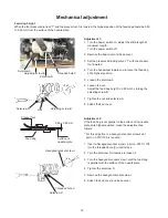
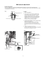
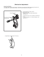
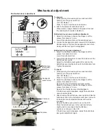
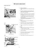
Presser bar lifter switch position adjustment
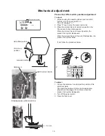
PRESSER BAR LIFTER SWITCH
Setscrew A
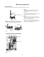
4 – 5.5 mm
Normal up
position
Extra lifted position
Lowered position
SWITCH SET PLATE
To check:
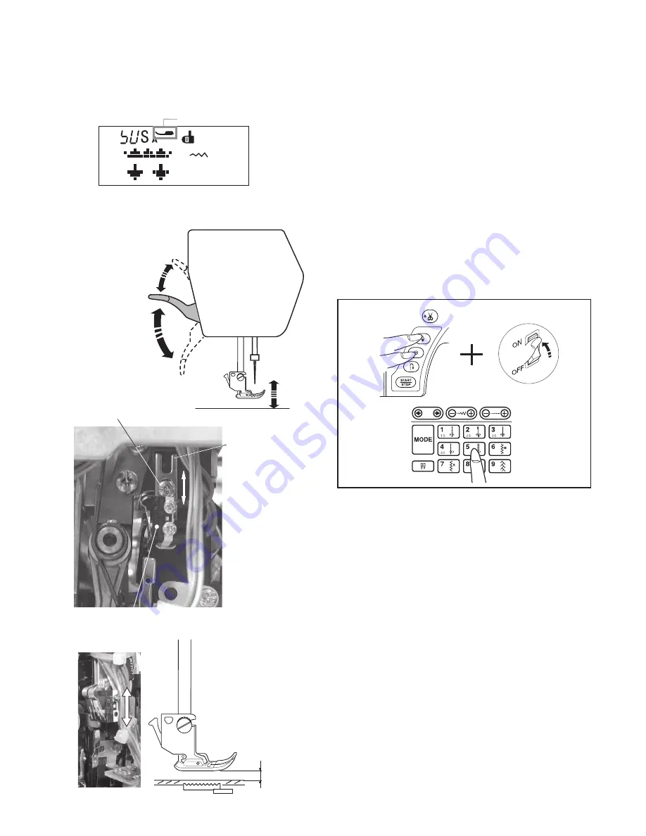
1. While pressing the needle up/down and lock stitch
buttons, turn the power switch on.
The LCD displays "----".
2. Press "5" key to enter the sesor test mode.
3. When the presser bar is at normal up position, the
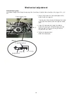
The presser foot symbol appears.
When the presser bar is at lowered position, the
presser foot symbol disappears.
When the presser bar is at the extra lifted position, the
presser foot symbol blinks.
If not, follow the procedure below.
To adjust:
1. Loosen the setscrew A and adjust the position of the
switch set plate.
The clearance between the foot and needle plate
should be in the range of 4 to 5.5 mm when the
presser foot symbol disappears.
2. Turn off the power switch.
3. Close the face cover.
1
2
Presser foot symbol


