56
02-147015-00-00.fm
Use
2.3.2
Comfort steering wheel (optional)
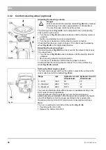
Adjusting the steering column
The steering column
can be adjusted to the corresponding
driver position with a lever.
•
Turn the lever
counter-clockwise until the steering column is
unlocked.
•
Set the required steering column adjustment.
•
Turn the lever clockwise until the steering column is locked.
Check that the steering column is locked. To do this move the steering
wheel
in the longitudinal direction.
Adjusting the steering wheel
The steering wheel
can be moved to the relevant driver posi-
tion using a lever.
•
Turn the lever
counter-clockwise until the steering wheel is
unlocked.
•
Move steering wheel to required position.
•
Turn the lever clockwise until the steering wheel is locked.
Check whether the steering wheel is locked. To do this, pull steering
wheel
upwards.
Setting the fixed engine speed
The fixed engine speed and thus the system output of the vehicle in the
work mode is set with the button
.
The overview illustrates that sufficient power is available already in the
ECO mode for many applications.
The full hydraulic output is reached as from the Standard speed.
Additional energy is available in the driving mode as well as in hydraulic
circuit II at Maximum. Set the speed according to the requirements.
Operation primarily in the ECO mode lowers consumption and noise.
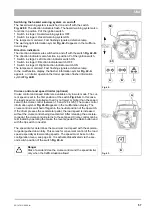
Horn
The horn is switched on and off with the button
.
•
Push the button: Horn ON
•
Release the button: Horn OFF
Fig. 40:
A
B
Danger
Risk of accident! If the steering column
-
is unlocked
while driving, it can come unexpectedly out of adjustment.
You can then lose control over the vehicle.
Fig. 41:
Stage
rpm
Hydraulic circuit I
Litres/minute
Hydraulic circuit II
Litres/minute
1 – ECO
1600
50
20
2 – Standard
2000
50/70
27
3 – Maximum
2400
50/70
32
Summary of Contents for Citymaster 650
Page 23: ...01 147015 00 00 fm 23 Safety Instructions G A B D E F Fig 3 C F E C D G A A B H H C...
Page 27: ...02 147015 00 00 fm 27 Use Fig 5 24 19 25 23 22 21 20 16 18 17 10 26...
Page 31: ...02 147015 00 00 fm 31 Use Fig 7 63 64 66 65 62 68 67 56 51 52 55 54 53 59 58 60 61 57...
Page 33: ...02 147015 00 00 fm 33 Use Fig 8 74 69 76 70 72 71 77 78 79 80 81 73 75 82...
Page 97: ...04 147015 00 00 fm 97 Technical data 4 Technical data Fig 96 1270 982 3326 2269 866 1074 1200...


