143
should now be checked in the »
Servo display
«
menu:
• The aileron servos 8 + 1 and 6 + 7 should move
exactly in parallel with servos 2 + 5; the aileron
trim lever acts upon servos 2 + 5 and 8 + 1, and
…
• … the Ch1 stick still operates no servos.
Caution:
Check the screen carefully! When the ailerons are
operated, the bars in the »
Servo display
« should
move in the same direction, but in opposite directions
when the fl aps are deployed.
The next step is to select the menu ...
»Servo adjustment« (page 56)
S e r v o 1
= >
0 % 1 0 0 % 1 0 0 % 1 5 0 % 1 5 0 %
S e r v o 2 = >
0 % 1 0 0 % 1 0 0 % 1 5 0 % 1 5 0 %
S e r v o 3 = >
0 % 1 0 0 % 1 0 0 % 1 5 0 % 1 5 0 %
S e r v o 4 = >
0 % 1 0 0 % 1 0 0 % 1 5 0 % 1 5 0 %
R e v c e n t . - t r a v e l + - l i m i t +
S E L
S E L
S Y M A S Y
S Y M A S Y
t
… and make any changes required to obtain the cor-
rect directions of servo rotation and travel.
This completes the basic programming of the six-
fl ap wing.
Flap settings in different fl ight phases
The fl ap positions can now be programmed to diffe-
rent settings for each fl ight phase.
Start by programming two or more fl ight phases using
the menus »
Phase setting
« and »
Phase assign-
ment
«. An example of programming fl ight phases can
be found on page 134.
When you have completed this stage, move to the
menu ...
»Control adjust« (page 58)
TRAVEL
TIME
… which allows you to set the fl ap positions separate-
ly for each fl ight phase.
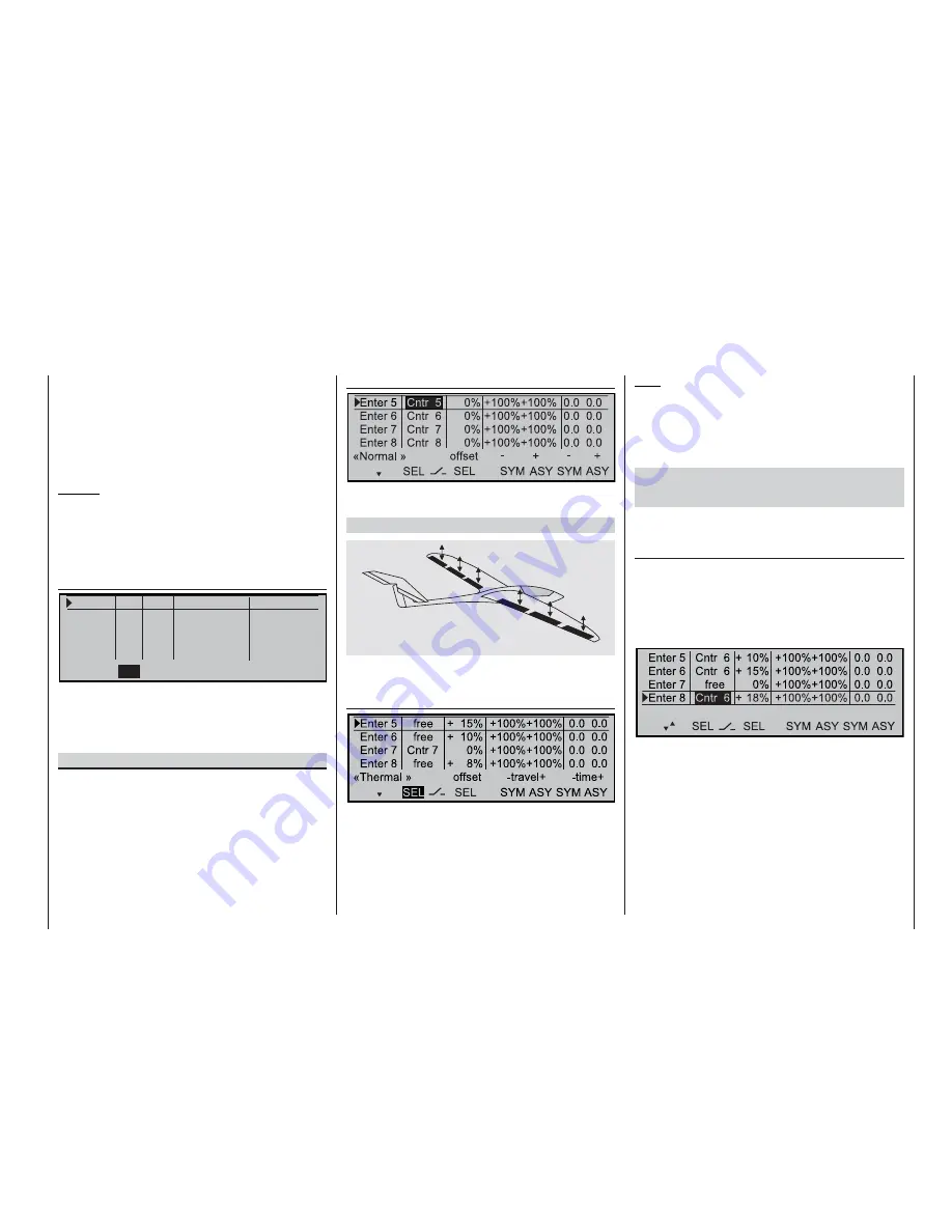
One fl ap setting for each fl ight phase
If one fl ap position is suffi cient for each fl ight phase,
move to the menu …
»Control adjust« (page 58)
… and select the offset for inputs 5, 6 and 8 to match
the position of the fl aps (“phase trimming”).
At the same time set inputs 5, 6 and 8 to “free” in
each fl ight phase, so that any accidental movement
of transmitter controls assigned to those inputs do not
affect the wing fl aps.
Note:
The offset required may need to be positive or nega-
tive; this depends on the orientation of the servos in
the wings.
However, you may prefer to set up an alternative con-
trol method, such as …
Variable fl ap positions in each fl ight phase using
only one slider (Order No. 4152) or a three-positi-
on switch module (Order No. 4151).
It is also possible to control all six wing fl aps using
only a single transmitter control. In the menu ...
»Control adjust« (page 58)
… assign the same slider or switch module connec-
ted to the transmitter circuit board, e.g. control 6, to
inputs 5, 6
and
8. Ideally this would be a different
transmitter control in each fl ight phase, so that the
correct settings, once found, are retained when you
switch from one fl ight phase to another:
OFFSET
TRAVEL
TIME
i4HERMALw
If you are using a switch, set the “deviation” from the
offset point
SYM
metrically or
ASY
mmetrically in the
“–” column.
However, if you wish to use a slider or rotary knob to
position your model’s fl aps, you should reduce travel
to about 50% or even less in the same menu, as this
gives you much fi ner control of the fl ap trim.
Programming examples – Fixed-wing models
Summary of Contents for MC-22S
Page 1: ...1 mc 22s GB mc 22s 3D Rotary Programming System Programming manual ...
Page 33: ...33 Digital trims ...
Page 55: ...55 Program description Base setup model ...
Page 77: ...77 Program description Flight phases ...
Page 89: ...89 Program description Mixers ...
Page 174: ...174 ...
Page 175: ...175 ...
Page 176: ...176 ...
Page 177: ...177 ...
Page 178: ...178 ...


