135
Programming examples – Fixed-wing models
The model settings you programmed before you as-
signed the phase switch are now to be found in the
fl ight phase «1 Normal». That is the phase which is
called up when the switch is at the centre position.
3rd step
You have already programmed all the settings for your
model in the primary fl ight phase, and you can avo-
id having to enter all the data again in the “new” fl ight
phases (although you could do that, if you really wan-
ted to) by copying the programmed settings – which
you know from test-fl ying to be correct – from the
«Normal» fl ight phase into the other two phases.
This is carried out in the menu ...
»Copy / Erase« (page 47)
Select the menu point “Copy fl ight phase” with the ro-
tary control pressed in, then press
ENTER
or give a
brief press on the rotary control.
A window now appears entitled “Copy from phase”; in
it select “1 Normal” ...
C o p y
f r o m p h a s e :
1 N o r m a l
2 T h e r m a l
3 S p e e d
4
… and then press
ENTER
again; the screen re-
sponds by switching to “Copy to phase”. Select the
destination (initially “2 Thermal”), and confi rm by
pressing
ENTER
again. Confi rm your selection in the
security query which subsequently appears, then wait
while all the settings as defi ned in your programming
are copied to the second phase.
Use the same procedure to copy the data to the third
phase (normal
speed).
4th step
At this point all three phases are programmed and all
the settings are copied; a “smooth” transition has also
been programmed, but ... there are no settings which
are specifi c to the different fl ight phases, i.e. all the
phase settings are the same.
To program these settings, call up the menu ...
»Wing mixers« (page 84)
A i l e r o n d i f f e r e n c e
+ 0 %
F l a p d i f f e r e n c e
+ 0 %
A i l e r o n s 2 > 4 R u d d e r
+ 0 %
A i l e r o n s 2 > 7 F l a p s
+ 0 %
B r a k e
> 3 E l e v a t o r
+ 0 %
« N o r m a l »
S E L
t
s
… and you will see the name of the current fl ight
phase at the bottom edge of the screen. If you now
change the position of the phase switch, the name of
the new fl ight phase assigned to that switch position
appears, but the settings are still those copied from
the «Normal» fl ight phase. At this point you can make
the changes as required by the new fl ight phase –
which will vary according to the phase you have se-
lected by the switch position.
Note:
The displayed list of mixers varies according to the
model type you have selected.
Once you have programmed all the settings, you
will be able to switch to and fro between the various
fl ight phases. However, when you operate the switch
you will soon realise that nothing has changed in the
basic settings of the control surfaces!
5th step
At this stage we have to make adjustments to meet
the differing requirements of the individual fl ight pha-
ses. This is carried out in the menu ...
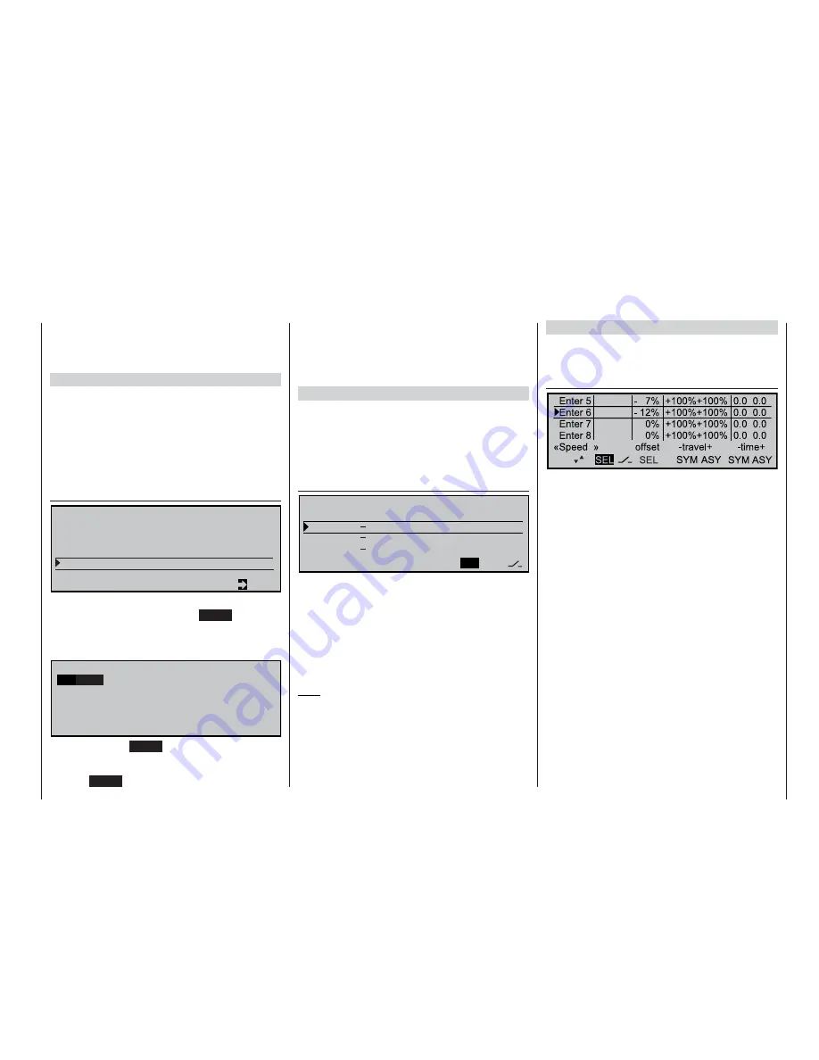
»Control adjust« (page 58)
FREE
FREE
#NTR
#NTR
Move to the “Offset” column and modify the settings
for (say) the ailerons and camber-changing fl aps in-
sofar as they differ from the «Normal» fl ight phase.
Note these points: “Offset control 5” affects the aile-
rons, “Offset control 6” applies to the fl aps. You can
change the travels in either the positive or negative
direction. Any elevator trim change required is made
using the option “Flaps 6
3 elevator” in the »
Wing
mixers«
menu. These adjustments have to be carried
out separately for each fl ight phase.
E r a s e m o d e l
= >
C o p y m o d e l
®
m o d e l
= >
C o p y M C 2 2
®
e x t e r n a l
= >
C o p y e x t e r n a l
®
M C 2 2
= >
C o p y f l i g h t p h a s e
= >
S e c u r e a l l m o d e l s
®
P C
= >
t
s
Summary of Contents for MC-22S
Page 1: ...1 mc 22s GB mc 22s 3D Rotary Programming System Programming manual ...
Page 33: ...33 Digital trims ...
Page 55: ...55 Program description Base setup model ...
Page 77: ...77 Program description Flight phases ...
Page 89: ...89 Program description Mixers ...
Page 174: ...174 ...
Page 175: ...175 ...
Page 176: ...176 ...
Page 177: ...177 ...
Page 178: ...178 ...


