


56
Column 3 “cent.”
The facility to offset the servo travel centre is intended
for adjusting servos whose centre setting is not stan-
dard (servo centre point at 1.5 ms), and also for minor
adjustments, e.g. for fi ne-tuning the neutral position of
the model’s control surfaces.
The neutral position can be shifted within the range
-125% to +125% of normal servo travel, regardless
of the trim lever position and any mixers you have set
up. The centre setting affects the associated servo di-
rectly, independently of all other trim and mixer set-
tings.
Pressing
CLEAR
resets the value to “0%”.
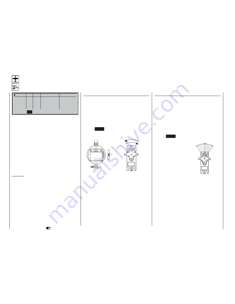
Column 2 “Rev”
The direction of servo rotation can be adjusted to suit
the actual installation in your model. This means that
you don’t need to concern yourself with servo direc-
tions when installing the mechanical linkages in the
model, as you can reverse them if necessary. The di-
rection of rotation is indicated by the symbols “=>”
and “<=”. Be sure to set the appropriate direction of
servo rotation before you start adjusting the remai-
ning options!
Pressing
CLEAR
resets the direction of rotation to
“=>”.
normal
reversed
normal
reversed
Servo adjustment
Servo direction, centre, travel, limit
S e r v o 1
= >
0 % 1 0 0 % 1 0 0 % 1 5 0 % 1 5 0 %
S e r v o 2 = >
0 % 1 0 0 % 1 0 0 % 1 5 0 % 1 5 0 %
S e r v o 3 = >
0 % 1 0 0 % 1 0 0 % 1 5 0 % 1 5 0 %
S e r v o 4 = >
0 % 1 0 0 % 1 0 0 % 1 5 0 % 1 5 0 %
R e v c e n t . - t r a v e l + - l i m i t +
S E L
S E L
S Y M A S Y
S Y M A S Y
t
In this menu you can adjust parameters which only
affect the servo connected to a particular receiver
output, namely the direction of servo rotation, neutral
point, servo travel and (if required) a travel limit.
The basic procedure:
1. Hold the rotary control pressed in and select the
relevant servo (1 to 12).
2. Turn the rotary control to select
SEL
,
SYM
or
ASY
in the bottom line, prior to making the adjustments
required.
3. Press the rotary control: the corresponding input
fi eld goes into inverse video (black background).
4. Set the appropriate value using the rotary control.
5. Finally press the rotary control again to end the in-
put process.
Important:
The numbers in the servo designations refer to the
receiver output socket to which a particular servo is
connected. These numbers do not necessarily coinci-
de with the numbering of the transmitter control func-
tion inputs, and indeed any coincidence would be pu-
rely accidental. The sophisticated programs of the
mc-22s mean that the numbers are unlikely to be the
same in any case. For example, changing the stick
mode does not affect the numbering (i.e. receiver so-
cket sequence) of the servos.
As a basic rule, always start with the servo setting in
the left-hand column!
Program description:
Base setup model
-125%
+125%
0 0
Servo centre adjustment
Summary of Contents for MC-22S
Page 1: ...1 mc 22s GB mc 22s 3D Rotary Programming System Programming manual ...
Page 33: ...33 Digital trims ...
Page 55: ...55 Program description Base setup model ...
Page 77: ...77 Program description Flight phases ...
Page 89: ...89 Program description Mixers ...
Page 174: ...174 ...
Page 175: ...175 ...
Page 176: ...176 ...
Page 177: ...177 ...
Page 178: ...178 ...


