306
Programming examples - F3A model
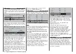
-50 % of control travel then briefl y tap on the
center
SET
key of the right touch pad.
In order to attain the curve shape shown, raise this
•
point with the selection keys to approx. 0 % in the
inverse video value fi eld in the "Point" line.
Finally, round the characteristic curve by moving
•
the marker frame left, select with a brief tap on the
center
SET
key of the right touch pad then change
the value from "Off" to "On" with the selection
keys.
If additional interpolation points between the left ("L")
and right ("H") end are necessary, repeat Steps 2 and
3 analogously.
Since F3A models normally have two aileron servos,
experience has shown that it is benefi cial to move
both ailerons upward
somewhat
when landing. In the
process, the model usually approaches somewhat
slower and, above all, more
steadily
for the landing.
In order to do this it is necessary to program mixers
through the menu …
»Free mixers«
(beginning page 193)
... accordingly.
The ailerons are extended as landing assistance
depending on the position of the throttle stick, starting
from approximately half throttle toward idle. The
further the joystick is moved toward idle, the more
the ailerons defl ect upward. Just the opposite applies
when "throttling"; the ailerons are retracted again in
order to prevent a sudden rise of the model.
In order to prevent the model from climbing with the
aileron landing fl aps extended, the elevator must be
mixed in somewhat.
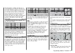
For this purpose, set the two linear mixers shown
in the following display. The activation of the mixers
takes place with one and the same switch, such
as "8", to which both mixers must be assigned with
identical switching direction.
5
LinearMIX 1
type
C1
from
– Begr. +
EL
C1
??
??
??
??
??
??
––––
LinearMIX 2
LinearMIX 3
LinearMIX 4
LinearMIX 5
to
Adjust
Tr
––––
––––
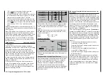
Then switch to the second respective display screen
in order to adjust the respective mixing degrees. In
both cases the mixer neutral point is at the C1 control
center.
Enter 0 % above the control center after selection of
the
ASY
fi eld for both mixers and below the control
center toward idle for:
MIX 1:
-60 % ... -80 % and
MIX 2:
-5 % ... -10 % ...
Example Linear MIX 1:
C1
Mix input
0%
Offset
0%
5
Linear MIX 1
–70%
SYM ASY
SET
STO
With this, the base setup model of an F3A model is
concluded.
Compensation of model-specifi c errors
Unfortunately, there are nearly always minor model-
specifi c "errors" through the mixers of a computer
remote control which must be compensated for.
However, before you begin with these settings,
it should be ensured that the model is faultlessly
constructed, optimally balanced over the longitudinal
and transverse axes and the down thrust and side
thrust are correct.
Infl uence of longitudinal and transverse axes by
the rudder
The actuation of the rudder often infl uences the
behavior of the longitudinal and transverse axes. This
is particularly disruptive in so-called knife-edge fl ying,
in which the lift of the model with the rudder defl ected
should be created by the fuselage alone. In the
process, the model can rotate and change directions
as though it were controlled with the ailerons and
elevator. Therefore, a correction over the transverse
axis (elevator) and/or the longitudinal axis (ailerons)
must be made, if applicable.
This can also be done easily with the »
Free mixers
«
available in the
mc-20
HoTT system. For example, if
the model drifts away to the right over the longitudinal
axis with the rudder extended in knife-edge fl ying, the
aileron can be defl ected slightly to the left with the
mixer. Changes in direction over the transverse axis
can be performed analogously with a mixer on the
elevator:
Correction over the transverse axis (elevator)
•
Linear MIX 3: "Rudd
¼
Elev"
Asymmetric setting. The appropriate values must
be tested in fl ight.
Correction over the longitudinal axis (aileron)
•
Linear MIX 4: "Rudd
¼
AIL"
Asymmetric setting. The appropriate values must
be tested in fl ight.
Relatively small mixer values are usually suffi cient
in this case, the range lies below 10 %, but can vary
from model to model. With the use of curve mixers,
the mix ratios can be adapted even more precisely
to the corresponding throw of the rudder. Again, no
values are indicated for this, because this would be
model-specifi c.
Summary of Contents for 32032
Page 1: ...33020 mc 20HoTT 2 en Programming Manual o Pro Pro mc 20 mc 20...
Page 15: ...15 For your notes...
Page 21: ......
Page 27: ...27 For your notes...
Page 41: ...41 For your notes...
Page 53: ...53 For your notes...
Page 59: ...59 For your notes...
Page 63: ...63 For your notes...
Page 93: ...93 For your notes...
Page 97: ...97 For your notes...
Page 141: ...141 How is a ight phase programmed...
Page 145: ...145 For your notes...
Page 155: ...155 For your notes...
Page 175: ...175 For your notes...
Page 203: ...203 For your notes...
Page 219: ...219 For your notes...
Page 253: ...253 For your notes...
Page 283: ...283 For your notes...
Page 321: ...321 For your notes...
Page 322: ...322 For your notes...
Page 323: ...323 For your notes...


