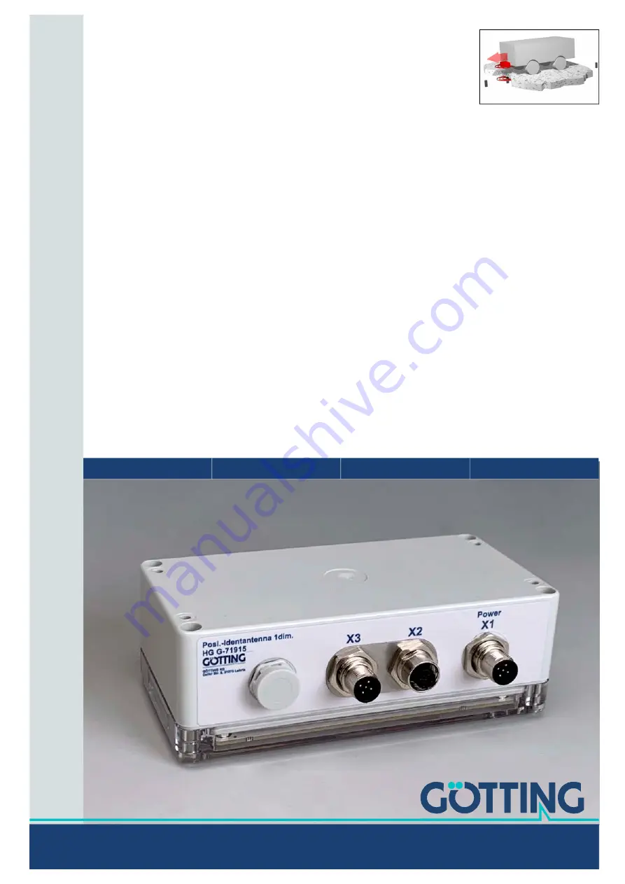
Transponder-Antenna
HG G-71915ZA
1-dimensional | CAN Bus | USB
English, Revision 01
Date: 09.09.2021
Dev. by: LM
Author(s): RAD/LM
Transponder
Device Description HG
G-71915ZA
Innovation through Guidance
www.goetting-agv.com
Page 1: ...nder Antenna HG G 71915ZA 1 dimensional CAN Bus USB English Revision 01 Date 09 09 2021 Dev by LM Author s RAD LM Transponder Device Description HG G 71915ZA Innovation through Guidance www goetting a...
Page 2: ...distance 5 80 mm depend ing on the transponder type see Table 47 on page 59 Voltage supply 18 30 VDC max crossing speed 2 0 m s 3x M12 connectors Data interface CAN Basic CAN Extended CANopen or Prof...
Page 3: ...ing Principle 18 5 1 Position Detection with Transponders 18 5 2 Reading Area and LEDs 19 6 Storage 20 7 Mounting 21 7 1 Mounting the Transponders 21 7 1 1 Operating Conditions for Transponders 21 7 2...
Page 4: ...Transponder Antenna Vehicle Controller 40 10 3 2 3 Transmission Box 2 Status Code Transponder Antenna Vehicle Controller 41 10 3 2 4 Transmission Box 3 Level Counter Transponder Antenna Vehicle Contr...
Page 5: ...71915ZA English Revision 01 Date 09 09 2021 5 Table of Contents 17 List of Tables 61 18 Index 63 19 Copyright and Terms of Liability 65 19 1 Copyright 65 19 2 Exclusion of Liability 65 19 3 Trade Mar...
Page 6: ...another way qualified persons who integrate the transponder antenna into a vehicle or mobile robot put it into operation for the first time or configure it 1 1 2 Additional Applicable Documents This d...
Page 7: ...or source of the danger The paragraph consequences describes the consequences of not heeding the warning The paragraphs for danger prevention explain how to avoid the danger The signal words have the...
Page 8: ...d width font Menu items and parameters are shown in cursive characters Whenever the pressing of letter keys is required for program entries the required etter eys are indicated as such for any program...
Page 9: ...der the corresponding sections Further informa tion can be found in section 5 2 on page 19 1 4 Abbreviations Table 2 Abbreviations Abbreviation Meaning AGV Automated Guided Vehicle CAN Controller Area...
Page 10: ...le and the transponders have a fixed position Position detection of moving parts e g on mobile robots or electric monorail conveyors i e the transponders move the antenna is located at a fixed posi ti...
Page 11: ...a has received this device description is familiar with the operation of the higher level system e g a vehicle is competent to perform his activities and is sufficiently trained in the installa tion a...
Page 12: ...f track Although dirt does not affect the position detection itself the transponder antenna should be protected from dirt and moisture e g splash water from the wheels of the vehicle and cleaned regul...
Page 13: ...available for the Profinet interface Refer to Table 3 for the order numbers of the required accessories Not all cables are required in every project For the transponder types common al ternatives with...
Page 14: ...puck transponder grey switching transponder HG G 70652ZC puck transponder black HG G 70653ZA puck transponder black HG G 70654ZB marking nail transponder yellow Table 4 Optional accessories Order No...
Page 15: ...ou can use a transponder programmer If the vehicle manufacturer or the plant operator does not yet have a controller for calculating the paths of the vehicle we recommend the navigation controller fro...
Page 16: ...patible with the transponder antenna including the order numbers can be found in Table 3 on page 13 4 2 Components in the Ground 4 2 1 Transponders Transponders with trovan coding are used as referenc...
Page 17: ...evice Overview Chapter 4 All cable connections are located on one side of the housing For dimensions see Figure 12 on page 26 The antenna has three M12 connectors the number of pins depends on the ant...
Page 18: ...th transponders in or on the ground and the antenna installed on the vehicle 5 1 Position Detection with Transponders In position detection with transponders the antenna permanently irradiates the are...
Page 19: ...der which half of the antenna a transponder is lo cated The antenna indicates its operating status via LEDs that illuminate the lane Thus even when the antenna is mounted under a vehicle one of the fo...
Page 20: ...e storage temperature is 40 C to 85 C Store the device in closed rooms only Make sure that the storage room is sufficiently ventilated and dry Protect the device from damage caused by dirt dust or moi...
Page 21: ...unted in standing water The plastic can absorb water over a longer period of time and weaken the transponder signal Reinforcements laid tightly under the road surface can interfere not only with the t...
Page 22: ...ng X1 Power The POWER connection contains the voltage supply the USB interface and the po sitioning pulse The output for the positioning pulse is supplied via Ub and is limited to 20 mA If you want to...
Page 23: ...sition data will be incor rectly evaluated by the higher level system and the vehicle may e g drive off track No interference signals from clocked motors etc may be present in the frequency range 64 4...
Page 24: ...sponder and Antenna Metal in the vicinity of the transponder and antenna affects the accuracy and range of the reading system A distinction is made between 1 Smaller metallic structures that do not fo...
Page 25: ...loops side view in the example transponder in the roadway Power lines e g for charging stations must not be laid in this area around the tran sponders as any pulses could make the code readings more...
Page 26: ...see Figure 12 Observe the orientation of the antenna when installing it Figure 12 Mounting options for the antenna To ensure that the system characteristics are not impaired Keep the mounting space a...
Page 27: ...antenna using the antenna internal monitor program see 8 3 on page 29 Saving the values and restarting the system 8 1 Connecting the Antenna to a Computer You can configure the system using a software...
Page 28: ...Microsoft Win dows It can also be downloaded for all Windows versions from the Internet at the following address https www hilgraeve com hyperterminal However any other terminal program that can hand...
Page 29: ...smission parameters for the CAN bus see 9 2 3 2 CAN Config on page 34 Position a transponder under the antenna and check whether all values arrive in your system via the corresponding interface Also u...
Page 30: ...rom the transponder antenna and maintaining constant reading dis tances from the transponders 8 4 Complete Commissioning If no errors have occurred Save the changed values see ection 9 2 4 on page 35...
Page 31: ...am This allows you to configure the antenna menu driven 9 1 Starting the Service Interrface As soon as the PC is connected to the antenna via the USB interface and the termi nal program is running the...
Page 32: ...lid transponder code detected at the sum signal Diff Valid transponder code detected at the difference signal Counter Sum Number of incorrect decoding attempts for the sum signal Diff Number of incorr...
Page 33: ...ult value of 150 has proven itself in test series and should only be changed in special cases A value that is set too high maximum value 999 reduces the read range A value that is selected too low lea...
Page 34: ...eenshot CAN 2 0B CANopen s section 9 2 3 2 on page 35 Baudrate 100 kBit s 125 kBit s 250 kBit s 500 kBit s 1 Mbit s Identifier RX Identifier of the reception box CAN 2 0A 0 7FF CAN 2 0B 0 1FFFFFFF Ide...
Page 35: ...CAN 2 0A CAN 2 0B CANopen selected in the screenshot Baudrate 100 kBit s 125 kBit s 250 kBit s 500 kBit s 1 Mbit s Node ID Participant address 1 127 TPDO1 Type 0 240 255 TPDO1 Inhibit Time 0 100 ms TP...
Page 36: ...er code by pressing the ENTER key 9 2 6 4 Data Logging Figure 21 Menu Data Logging For diagnostic purposes the following values can be output via the service interface Via the terminal program the val...
Page 37: ...the spreadsheet will ask for some op tions Specify there that the values are comma separated Afterwards the data can be prepared in chart form or saved as a native spreadsheet file for sharing 9 2 7...
Page 38: ...egram However the latency time of the data output period must be tak en into account In addition a CAN telegram without data content can also be trig gered directly by the positioning pulse see sectio...
Page 39: ...ended 29 bit identifier can be configured The CAN parameters can be set via the service interface see section 9 2 3 1 on page 34 Standard or Extended frames are sent and received adjustable The bit ti...
Page 40: ...amming process started After an antenna reset the code 0000 is in the memory of the antenna If the code 0000 is to be programmed it is recommended to send another code and then send the 0000 again If...
Page 41: ...us 1 Bit 8 15 3 Transponder code Bit 0 7 4 Transponder code Bit 8 15 5 Transponder code Bit 16 23 6 Transponder code Bit 24 31 7 Number of code readings since the last transponder crossing Table 13 CA...
Page 42: ...nt by a device RPDO Receive PDO The process data received by a device SDO Service data objects Used to read and write device param eters No size limit Sync Synchronization telegram Bus wide telegram s...
Page 43: ...values are assigned to fixed positions in the PDO dynamic mapping is not supported You can set the PDO operating mode to cyclic synchronous or asynchronous To avoid a too high bus load by constant ch...
Page 44: ...signed 32 Transponder code bit 0 7 4 Transponder code bit 8 15 5 Transponder code bit 16 23 6 Transponder code bit 24 31 7 Unsigned 8 Number of code readings since the last transponder crossing Table...
Page 45: ...the CANopen Object Index Each entry is a 16 bit index Sub components are identified by an 8 bit subindex RO indicates en tries that are read only Communication parameters are marked by a C Manufactur...
Page 46: ...f Objects mapped to RxPDO_1 1 RO Specification of Appl Object 1 0x1800 0 RO Number of entries of TxPDO_1 1 RW COB ID 2 RO Transmission Type 3 RW Inhibit Time 5 RW Event Time 0x1801 0 RO Number of entr...
Page 47: ...320 0 RO Number of 32 Bit Inputs Digital 1 RO New Transponder Code 0x6401 0 RO Number of 16 Bit Inputs Analog 1 RO Level Sum Signal 2 RO Level Difference Signal Table 26 CANopen Device Type Index Sub...
Page 48: ...at Time Index Sub Index Name Type Attr Map Default Meaning 0x1017 00 Producer Heartbeat Time Unsigned 16 RW No 1000 Heartbeat Zeit in ms approx Table 33 CANopen Identity Object Index Sub Index Name Ty...
Page 49: ...lt Meaning 0x1801 00 TxPDO Parame ter Unsigned 8 RO No 0x05 Number of sub indexes 01 COB ID Unsigned 32 RW No 0x40000180 Node ID PDO_2 valid ID 0x280 Node ID 02 Transmission Type Unsigned 8 RW No 1 24...
Page 50: ...Bit length 05 56th mapped object Unsigned 8 RO No 0x60000508 Mapped to Index 0x6000 05 with 8 Bit length Table 39 CANopen 8 Bit Digital Inputs bertragen in TxPDO 1 Index Sub Index Name Type Attr Map...
Page 51: ...able 42 CANopen 32 Bit Digital Output Index Sub Index Name Type Attr Map Default Meaning 0x6320 00 Number of 32 bit inputs Unsigned 8 RO No 1 Number of 32 Bit Inputs 01 32 bit digital output Unsigned...
Page 52: ...ware file is available on request from G tting KG The DfuSE software can be downloaded at the following address http www st com en development tools stsw stm32080 html 3 Download DfuSE install the pro...
Page 53: ...U mode can be left via Leave DFU mode and the program can be closed Figure 26 Firmware update leave DFU mode Afterwards the connection can be re established in the terminal program and the main menu o...
Page 54: ...ntennas tight fit of all screws cables and plugs properly fastened cleaning the antenna if it is dirty New firmware files are only provided by G tting KG if necessary If you have received a firmware u...
Page 55: ...e with the legal requirements of your country For EU countries only Do not dispose of the transponder antenna in household waste Collect used electrical equipment separately in compliance with Europea...
Page 56: ...ction range Voltage supply too low Measure the input voltage 2 Output values not repro ducible lack of accuracy faulty positioning pulses Interference Check the Sum value in the ser vice interface see...
Page 57: ...ol or parameters using a PC and the service interface 3 Hardware defect please contact the support of G tting KG 6 Parameter error indicated via LEDs s 14 2 below 1 Voltage failure during save attempt...
Page 58: ...pply voltage UB 18 VDC to 30 VDC nominal voltage 24 VDC Current consumption 130 mA 24 VDC Operating frequency 128 kHz Code length 16 Bit Trovan max crossing speed 2 0 m s Repeat accuracy 2 mm at 0 5 m...
Page 59: ...99 Disc transponder 5 60 mm HW DEV00130ZA VA Disc transponder 5 60 mm HW DEV00131ZA VA Disc transponder 5 60 mm HW DEV00162 Transponder credit card format 5 80 mm HG G 70650VA Puck transponder 5 80 m...
Page 60: ...enna and transponder with closed metallic structures or loops side view in the example transponder in the road way 25 Figure 12 Mounting options for the antenna 26 Figure 13 Connection example Connect...
Page 61: ...1 Status Code 44 Table 19 CANopen Structure of TxPDO_2 Level Counter 44 Table 20 CANopen Structure of RxPDO_1 transponder programming 44 Table 21 CANopen Codes of the heartbeat modes 45 Table 22 CANop...
Page 62: ...41 CANopen 32 Bit Digital Input 51 Table 42 CANopen 32 Bit Digital Output 51 Table 43 CANopen 16 Bit Analog Inputs 51 Table 44 Error table 56 Table 45 LEDs Blink codes for errors 57 Table 46 Technical...
Page 63: ...the Ground 16 System Components 15 Connection CAN Bus 22 Connection Box 14 Connection Cables Accessories 13 Preparation 22 Connection Example 25 Control Unit 14 Coordinate System of the Antenna 9 Cop...
Page 64: ...ons of the Operator 12 Scope of Delivery 13 Service Interface 29 Main Menu 31 Operation 31 Service Schnittstelle 31 Software 31 Specialist 11 Status 1 38 Status 2 39 Status Field 31 Storage 20 Symbols...
Page 65: ...valid if the systems are used according to the description This instruction manual has been drawn up to the best of our knowledge Installa tion setup and operation of the device will be on the custome...
Page 66: ...Innovation through Guidance G tting KG Celler Str 5 D 31275 Lehrte Tel 49 0 5136 8096 0 Fax 49 0 5136 8096 80 info goetting agv com www goetting agv com www goetting agv com...