


82
4. CONFIGURATION
80703B_MHW_2850T/3850T_02-2019_ENG
File name
Content
cfg
1. PID parameters
2. Internal simulator configurations
3. Analog input/output scaling
4. Comma management combined with
virtual analog variables (register, ret
register, etc.)
5. Unit of measure management com-
bined with variables
6. All instrument configurations are
associated with their use modes
(number of clocks, home page, pro-
gram operating mode, etc.)
7. Graph range, both real-time and log
custom_page Custom page
To select a configuration file just touch its name; the con-
tour of the corresponding row is highlighted. The icons and
buttons are used to:
Scroll down the list.
Scrolls the list upwards.
Indicates that a USB key is connected to the
controller.
It transfers the selected file from the USB key to
the controller memory.
Moves the selected file from the controller mem-
ory to the USB key.
Deletes the selected file in the list above.
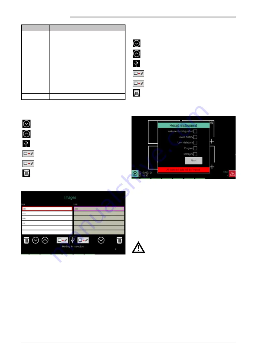
4.15.3.3. IMAGE
The
Image
page allows you to transfer images from a USB
key to the controller and vice versa, or erase them.
The images can be used in custom pages, as simple imag-
es or in two-state keys (key pressed and key not pressed).
Images can have dimensions up to 320 x 240 pixel for mod-
el 2850T and 800 x 480 pixel for model 3850T.
Images to be loaded must be in
.plk
format which is a Ge-
fran proprietary format.
Images in this format are authomatically made from GF_
eXpress configurator during download.
By inserting the USB key, the left column lists the images
stored in the controller, the right one containing the images
in the USB key.
To select an image, just touch its name; the contour of the
corresponding row is highlighted.
The icons and buttons are used to:
Scroll down the list.
Scrolls the list upwards.
Indicates that a USB key is connected to the
controller.
It transfers the selected image from the USB key
to the controller memory.
Moves the selected image from the controller
memory to the USB key.
Deletes the selected image in the list above.
4.15.3.4. “Controller model” RESET
The
Reset instrument
page lets you delete log, configura-
tion or program files.
Select the files to be deleted:
•
Instrument configuration
: all configurations are delet-
ed and the controller returns to factory settings.
•
Alarm history
: Datalogs and alarm logs are deleted.
•
User Database
: all users are deleted.
•
Program
: all programs are deleted.
•
The
Reset
button deletes data, and the
Cancel
button
closes the window without doing anything.
Warning!
The reset operation is not reversible.
Once deleted, data cannot be recovered unless
you have an external back-up copy.
4.15.4. PID CFG sub-menu
To use this sub-menu, the user must be level 1 or 2.
4.15.4.1. PID configuration procedure
The new PID configuration procedure is the following:
1. Log in as a Level 2 user.
2. Select the Synoptic section and set the PID operating
type: normal, cascade, valve or ratio.
3. Select the Variable section to link variables to inputs
and outputs.
4. Select the Alarm section to set PID alarms.
5. Select the Base section to enter all PID base parame-
ters. This section is made up of several pages accessi-
ble via the drop-down menu that opens by clicking on
the Base label.
Summary of Contents for 2850T
Page 2: ......
Page 6: ...80703B_MHW_2850T 3850T_02 2019_ENG 4...
Page 10: ...80703B_MHW_2850T 3850T_02 2019_ENG 8...
Page 20: ...80703B_MHW_2850T 3850T_02 2019_ENG 18...
Page 34: ...80703B_MHW_2850T 3850T_02 2019_ENG 32...
Page 104: ...80703B_MHW_2850T 3850T_02 2019_ENG 102...
Page 106: ...80703B_MHW_2850T 3850T_02 2019_ENG 104...
Page 124: ...80703B_MHW_2850T 3850T_02 2019_ENG 122...
Page 128: ...80703B_MHW_2850T 3850T_02 2019_ENG 126...
Page 156: ...80703B_MHW_2850T 3850T_02 2019_ENG 154...


