


133
9. 2850T-3850T configuration in GF_eXpress
80703B_MHW_2850T/3850T_02-2019_ENG
page 56.
When one of the Logical\Mathematical functions entered
is selected, press the right mouse button and a context-
specific menu will appear containing the following items:
• “Add” to add a new Logical\Mathematical function
following those already present (
• “Insert” to insert a new Logical\Mathematical function
in the position:
• “Before”
• “After”
• the selected position
• “Duplicate” to duplicate the selected Logical\
Mathematical function in the next position
• “Move” to move the selected Logical\Mathematical
function:
• up one position (“Up”)
• down one position (“Down”)
• before all the others (“First”)
• after all the others (“Last”)
• “Modify Type” to change the type of Logical\
Mathematical function to another in the same category
(if there are any)
• “Delete” to delete the selected Logical\Mathematical
function
(see image below)
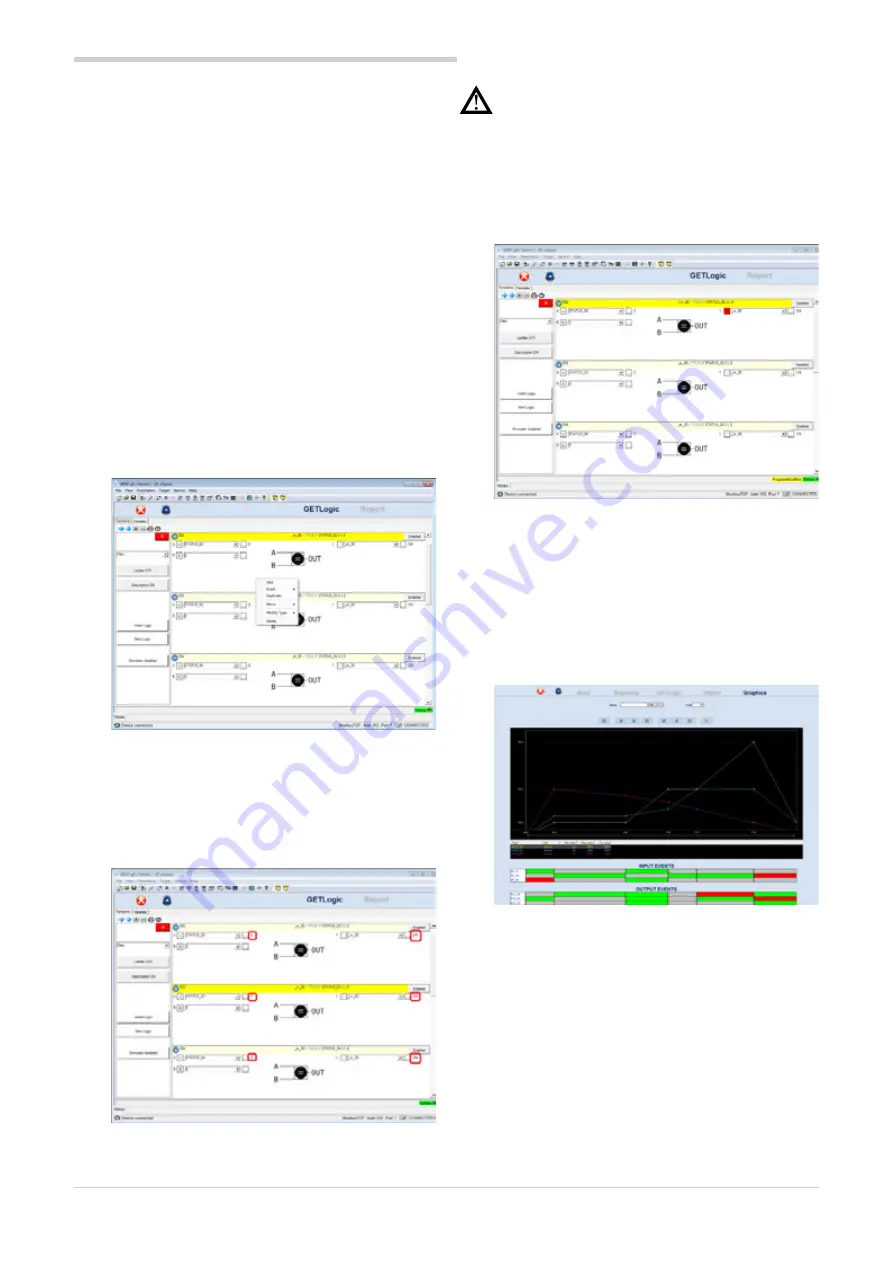
When the configurator is connected to the target, you may
view in real time:
• the value of the quantities constituting the input of the
various Logical\Mathematical functions
• and the corresponding value of the quantities
constituting the output of the various Logical\
Mathematical functions
(see image below).
Warning!
The values of the variables appearing in the
configurator are correct as long as the Logical\
Mathematical functions are updated to align them
with those in the target. If the user makes one
or more changes to the configurator, the words
“ProgramModified” will appear in yellow at the lower
right, reminding the user to transfer the change to the
target in order to align it with the configurator (see
image below).
9.4.1.2. “GRAPHICS” section
In the “Graphics” tab:
• N (where N is 1 to 4) synchronous profiles the user has
decided to define
• the status of digital inputs are shown/set to enable
transition to the next step (“INPUT EVENTS”)
• the value of digital outputs is shown\set at the end of
the generic step (“OUTPUT EVENTS”)
(see image below)
By clicking the mouse on the individual boxes in the sections:
• “INPUT EVENTS”
• “OUTPUT EVENTS”
the user can establish, respectively:
• the status the digital input must have, indicated at
the head of the row, at the start of the step under
examination to permit the profile generator to continue
• the value to be attributed to the digital output,
indicated at the head of the row, for the step under
examination
The admissible values are:
• green square: digital input status = 1 - digital output
value = 1
• red square: digital input status = 0 - digital output
value = 0
• grey square: digital input status to be ignored - digital
output value same as in previous step
Summary of Contents for 2850T
Page 2: ......
Page 6: ...80703B_MHW_2850T 3850T_02 2019_ENG 4...
Page 10: ...80703B_MHW_2850T 3850T_02 2019_ENG 8...
Page 20: ...80703B_MHW_2850T 3850T_02 2019_ENG 18...
Page 34: ...80703B_MHW_2850T 3850T_02 2019_ENG 32...
Page 104: ...80703B_MHW_2850T 3850T_02 2019_ENG 102...
Page 106: ...80703B_MHW_2850T 3850T_02 2019_ENG 104...
Page 124: ...80703B_MHW_2850T 3850T_02 2019_ENG 122...
Page 128: ...80703B_MHW_2850T 3850T_02 2019_ENG 126...
Page 156: ...80703B_MHW_2850T 3850T_02 2019_ENG 154...


