GE M
EDICAL
S
YSTEMS
D
IRECTION
2392751-100, R
EVISION
3
V
IVID
™ 4 S
ERVICE
M
ANUAL
Chapter 8 - Replacement Procedures
8-127
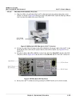
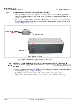
6.) Verify that the switches on the VCR rear panel are as shown in
below. If necessary,
adjust accordingly.
8-8-3-4
Sony VCR Installation Procedure
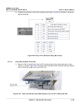
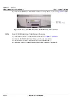
1.) Place the VCR on the
left
side of the Vivid™ 4 ultrasound unit’s top surface (below the control
console - as shown in
below) and next to the B/W Printer, if present, allowing sufficient
room to access the cables at the rear of the VCR.
Figure 8-121 Video Cassette Recorder (VCR) Installed in the Vivid™ 4 Ultrasound Unit
Figure 8-120 Sony VCR - Switches Setting (Rear Panel)
Switch
Position
VCR AUDIO SWITCHES (on Rear)
1
OFF
Audio/Video Mute during search
2
OFF
Search at high speed using FF/REW
3
OFF
Reset control counter when cassette is ejected
4
OFF
Enable RS232 remote
5
ON
Baud rate (see below)
6
ON
Baud rate (see below)
1 2 3 4 5 6
OFF
Switch 5
Switch 6
Baud rate
OFF
OFF
2400
OFF
ON
4800
ON
OFF
9500
ON
ON
10200
Video Cassette
Recorder (VCR)

