GE M
EDICAL
S
YSTEMS
D
IRECTION
2392751-100, R
EVISION
3
V
IVID
™ 4 S
ERVICE
M
ANUAL
4-4
Section 4-3 - Functional Check
4-3-1-2
Speakers Tests
4-3-1-3
Video Grabbing Test
4-3-2
Peripherals
4-3-2-1
VCR Test
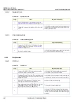
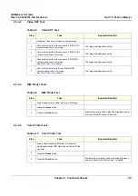
Table 4-5
Speakers Test
Step
Task
Expected Result(s)
1
Run the audio diagnostic, as described in the
(Doppler Sound Driver) Diagnostic Test
2
Change the frequency and speaker activity, from
right
to
left
.
Verify that there is clear sound from both speakers at all
frequencies. Note that
right
and
left
are as seen when
standing behind the unit.
Table 4-6
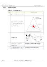
Video Grabbing Test
Step
Task
Expected Result(s)
1
Connect the Y/C OUT to the Y/C IN and run the video
grabbing calibration, as described in
2
Examine the grabbed image.
Verify that the grabbed image is stable and has similar
grey levels to that of the reference image.
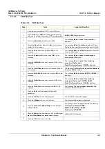
Table 4-7
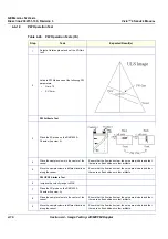
VCR Test
Step
Task
Expected Result(s)
1
Connect a Sony 9600 VCR to the system, restart the
system and load an SVHS cassette.
Verify that all the following cables are connected:
SVHS In/Out, Audio In/Out and RS232.
2
Connect a 3S probe. Reset the VCR counter and press
the
VCR Record
button using the indicated soft keys as
displayed on screen.
Verify that the recording indicator (red dot) is displayed
on-screen and the tape counter is running on-screen.
3
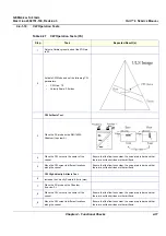
Activate CW Mode and record 2 minutes of heart
scanning or a similar effect using a phantom.
Record 2 minutes of CW scanning.
4
Stop recording and press the
Play B.
button, then use
the
Rewind
soft key to rewind the cassette to the
beginning before pressing the
Play
soft key.
The recorded Image is played back.
5
Verify that in CW Mode both the
left
and
right
audio
channels are working, and that the played back audio
is similar to the recorded audio in both the
left
and
right
speakers.

