GE M
EDICAL
S
YSTEMS
D
IRECTION
2392751-100, R
EVISION
3
V
IVID
™ 4 S
ERVICE
M
ANUAL
8-16
Section 8-2 - Cover Replacement Procedures
8-2-9
Control Console Upper Cover (Rear) Replacement Procedure
NOTE:
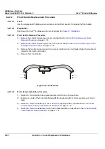
The Vivid™ 4 control console upper cover (new type) has two components - Front (P/N 2405642) and
Rear (P/N 2405643). This section describes the removal and installation procedures for the
Rear
only.
For instructions on replacing the Front component, refer to the
Control Console Upper Cover (Front)
8-2-9-1
Tools
Use the appropriate Phillips-type screw drivers, as indicated in the upper cover (rear) replacement
procedures.
8-2-9-2
Preparation
Shut down the Vivid™ 4 ultrasound unit, as described in
.
8-2-9-3
Control Console Upper Cover (Rear) Removal Procedure
1) Raise the control console monitor to its
maximum
height.
2) Remove the 17" Monitor as described in the
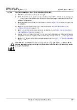
CAUTION: The Vivid™ 4 17" monitor is heavy. At least two people must be available to lift the
monitor. Attempts to move this unit by one person alone, could result in personal injury, and/or
damage to the system!
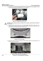
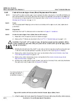
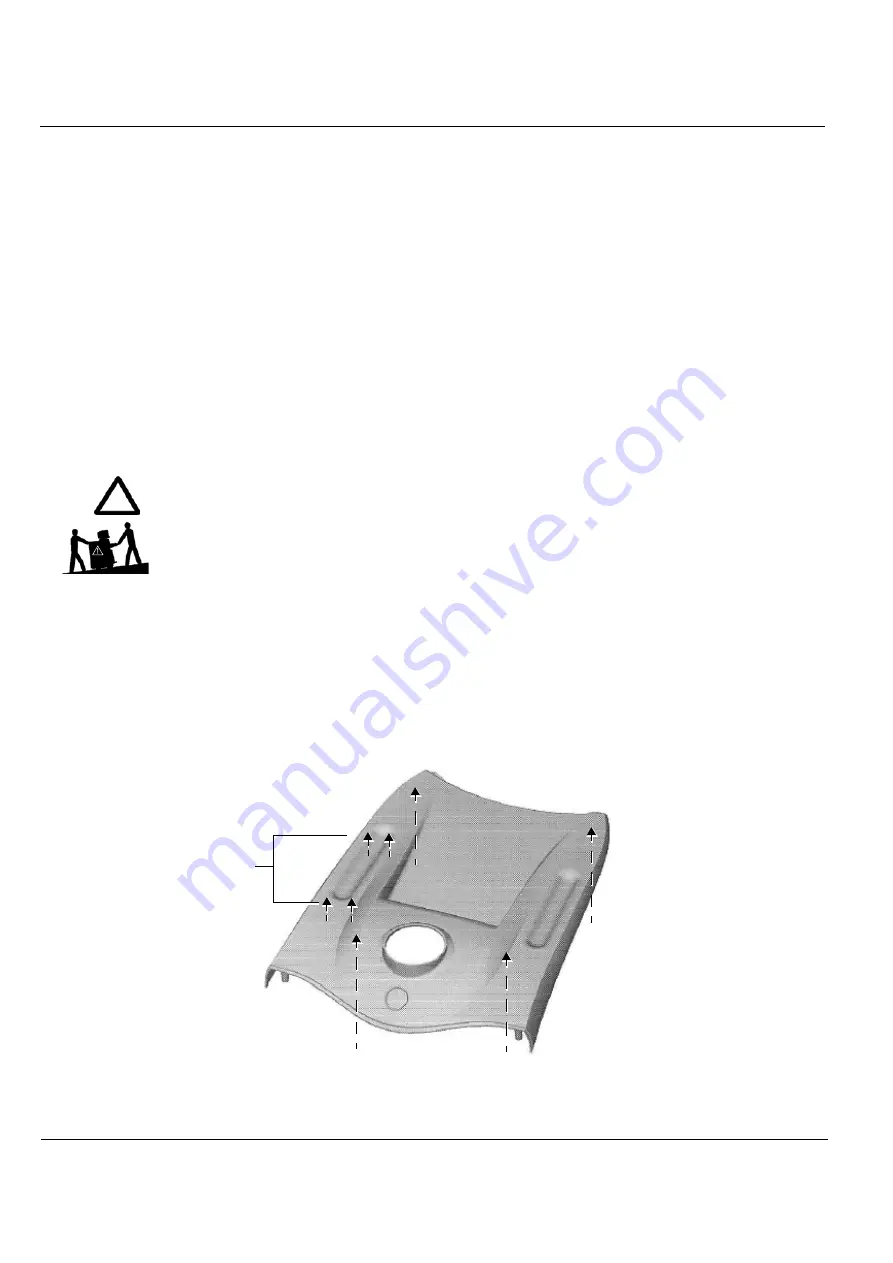
3) Working from the
left
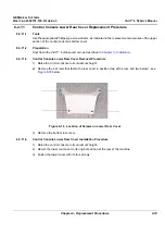
side of the Vivid™ 4 unit, remove the 4 screws securing the rectangular cover
in the roof of the side compartment in position; remove the cover (see
4) Remove the control console lower rear cover, as described in the
5.) Remove the control console lower cover, as described in the
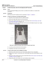
6) Working from underneath the control console, remove the 4 screws (2 from each side) that fasten
the upper rear cover in place (refer to
Figure 8-16 Location of Screws on the Control Console Upper (Rear) Cover
7.) Lift up the upper rear cover (away from the upper front cover) and remove from the control console.
Four screws fastened
through roof of side
compartment (step 3)


