3. VERTICAL MODE
3-5
3.3.3
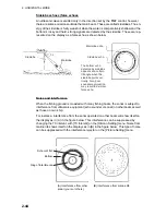
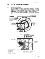
Cursor position reference mark
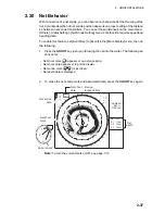
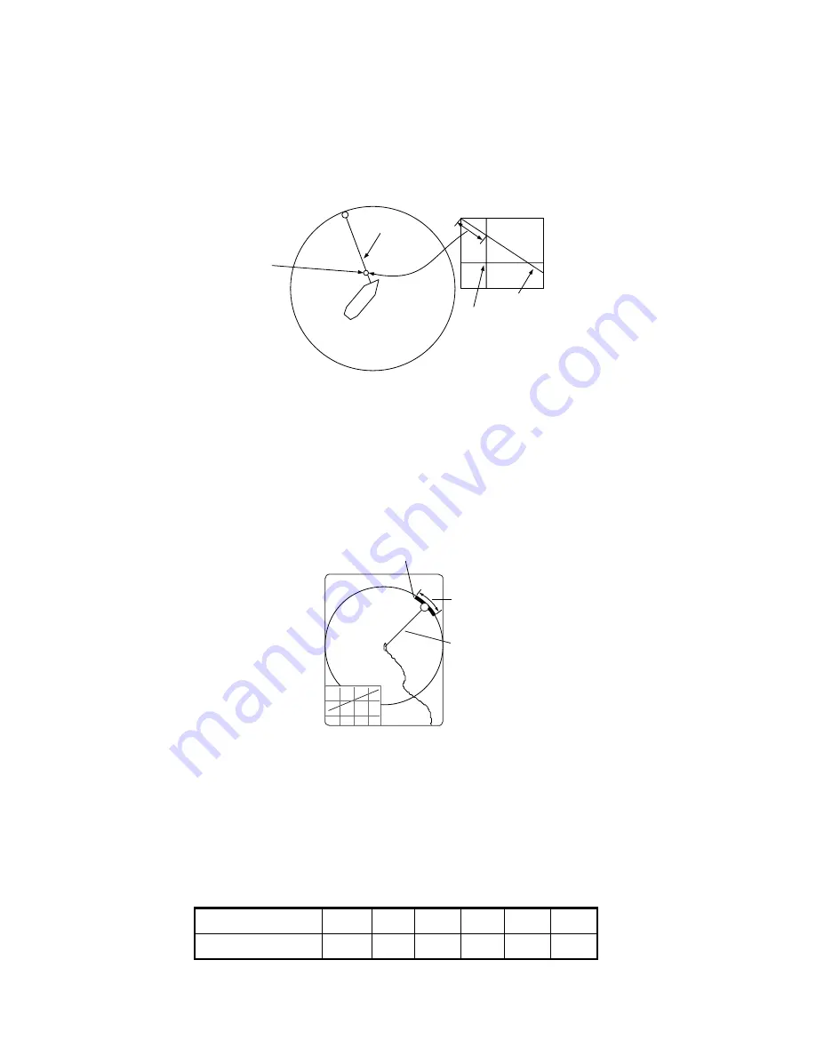
The cursor position reference mark, a solid circle, is inscribed on the vertical bearing
mark when the cursor is placed in the vertical display. Its purpose is to show corre-
sponding cursor position on the horizontal display. It changes position with cursor po-
sition, tilt and range, and disappears when its position is no longer within the range of
the horizontal display.
3.4
Auto Train
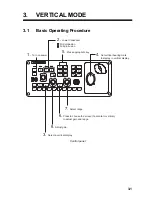
You may scan the vertical bearing mark in the sector of ±12°, ±24° and ±36°. Press
and hold down the
AUTO TRAIN
key while pressing the
V1/S
or
V2
key to select the
auto train sector desired. Selected sector appears in large characters for five seconds
for your confirmation. To cancel auto train, repeat the above procedure to select
[OFF].
3.5
Display Range
The
RANGE
control selects the detection range. The range selected is momentarily
displayed in large characters at the top of the vertical 1 display. Range is always dis-
played next to “R“ at the lower part of the vertical 1 display.
The default ranges are as shown below. In the vertical 2 combination display, the
range for V1 and V2 are same.
Note:
Ranges can be preset. See page 7-6 for details.
Range No.
1
2
3
4
5
6
Detection range
100
200
400
600
800
1000
VERTICAL
DISPLAY
Cursor
Cursor
position
reference
mark
V
Vertical
bearing
mark
Tilt mark
Vertical
bearing
mark
Auto train mark
1
Auto train
sector
Summary of Contents for FSV-85
Page 1: ...COLOR SCANNING SONAR FSV 85 OPERATOR S MANUAL www furuno com Model ...
Page 128: ...5 NUMERIC GRAPHIC DATA DISPLAY 5 4 This page is intentionally left blank ...
Page 158: ...8 RECORD RECALL OPERATION 8 8 This page is intentionally left blank ...
Page 172: ...9 MAINTENANCE TROUBLESHOOTING 9 14 This page is intentionally left blank ...
Page 178: ...APPENDIX 1 MENU TREE AP 6 This page is intentionally left blank ...
Page 184: ......

