2. HORIZONTAL MODE
2-20
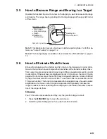
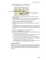
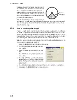
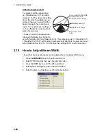
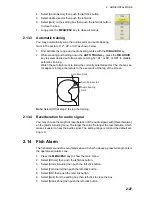
Sidelobe suppression B
For greater sidelobe suppression,
use [Sidelobe Sup. B]. The setting
range is 1 to 5. The larger the setting
value, the more the sidelobe is sup-
pressed; however, the width of the
beam increases thus resolution is
lower. The negative value setting (-5
to -1) is effective for reducing the ef-
fects of screw noise.
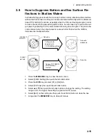
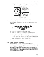
The area in which to suppress side-
lobes with [Sidelobe Sup. B] can be
set with [Sidelobe Dir1] and [Sidelobe Dir2]. The setting range is 0°
≤
[Sidelobe Dir1]
≤
[Sidelobe Dir2]
≤
180°, symmetrical in port-starboard directions. An area can be set
when [Sidelobe Sup. B] is 0 - 5. In this case the settings of Dir1 and Dir2 are gray.
2.10
How to Adjust Beam Width
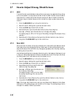
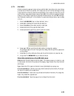
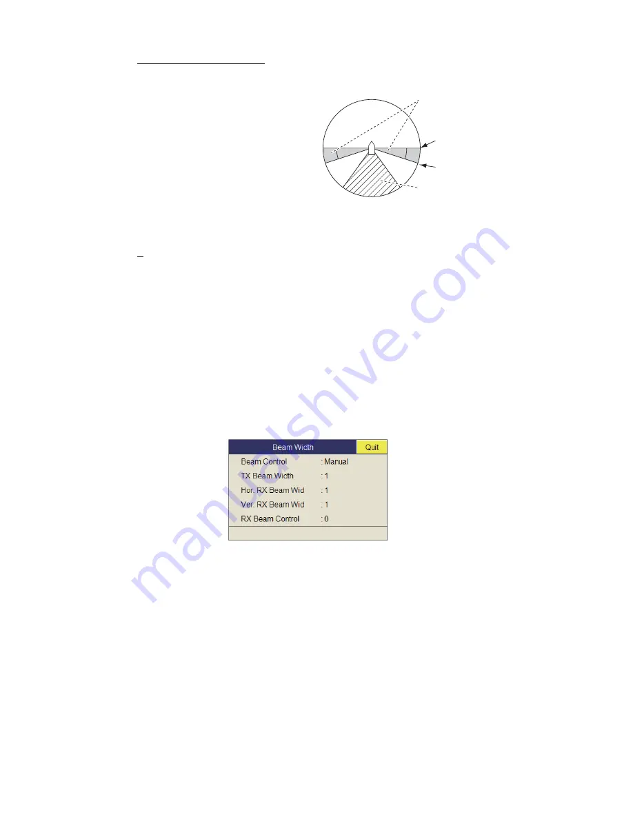
The width of the horizontal beam can be adjusted from the [Beam Width] menu.
1. Press the
MENU/ESC
key to show the main menu.
2. Select [TX/RX Setting] then push the left-click button.
3. Press the
H/V/S
key to select the [H1] or [H2] tab.
4. Select [Beam Width] then push the left-click button.
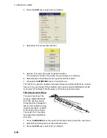
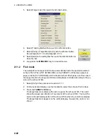
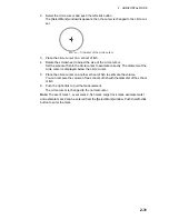
5. Select the item to adjust then push the left-click button.
Sidelobe bearing 1
Sidelobe bearing 2
Area in which SIDELOBE
SUP. B works (port-
starboard symmetrical)
Echo from screw
noise
Summary of Contents for FSV-85
Page 1: ...COLOR SCANNING SONAR FSV 85 OPERATOR S MANUAL www furuno com Model ...
Page 128: ...5 NUMERIC GRAPHIC DATA DISPLAY 5 4 This page is intentionally left blank ...
Page 158: ...8 RECORD RECALL OPERATION 8 8 This page is intentionally left blank ...
Page 172: ...9 MAINTENANCE TROUBLESHOOTING 9 14 This page is intentionally left blank ...
Page 178: ...APPENDIX 1 MENU TREE AP 6 This page is intentionally left blank ...
Page 184: ......

